Proline PROMAX MIG-250DP User manual

MIG-250DP
Owners Manual

Congratulations on your purchase of a new
PROMAX MIG-250DP D/Pulse Mig Welder.
We are proud to have you as our customer and
will strive to provide you with the best service
and reliability in the industry.
This product is backed by a 12-month trade
warranty.
Proline Welding Supplies would like to thank you
for your business, we look forward to as-sisting
with any technical support or welding supplies
required to keep your welder operating.
Please contact the friendly team:
Proline Welding Supplies
Phone: 0800 699 353 | Email:
Website: www.prolineindustrial.co.nz

- 1 -
SAFETY INSTRUCTIONS AND WARNINGS
Symbol Usage
This manual contains important information that you need to know and understand in
order to assure YOUR SAFETY and PROPER OPERATION of EQUIPMENT. The
following symbols help you recognize this information. Please read the manual and pay
attention to these sections.
Save These Important Safety Instructions!
Read and understand all of these safety instructions. Be sure to retain them for
future use.
WARNING!
Warnings indicate a certainty or strong possibility of personal injury or
death if instructions are not followed.
CAUTION:
Cautions indicate a possibility of equipment damage if instructions are
not followed properly.
NOTE:
Note gives helpful information
Welding products and welding processes can cause serious injury, death, or damage to
other equipment or property if the operator does not strictly observe all safety rules and
take precautionary actions.
Safety practices are outlined in the American National Standard Z49.1 entitled: SAFETY IN
WELDING AND CUTTING. This publication and other guides
to what you should learn before operating this equipment are listed at the end of these
safety precautions. HAVE ALL INSTALLATION, OPERATION, REPAIR WORK,
AND MAINTENANCE PERFORMED BY QUALIFIED PROFESSIONALS.
Welding Hazards
The symbols shown below are used throughout this manual to call attention to and identify
possible hazards. When you see the symbol, watch out, and follow the related instructions
to avoid the hazard. The safety information given below is only a summary of the more
complete safety information found in the Safety Standards listed in Section 1-4. Read and
follow all Safety Standards.
Electric Shock can kill.
Touching live electrical parts can cause fatal shocks or severe burns. The
electrode and work circuit is electrically live whenever the output is on. The
input power circuit and machine internal circuits are also live when power is on.
In semiautomatic or automatic wire welding, the wire, wire reel, drive roll
housing, and all metal parts touching the welding wire are electrically live.
Incorrectly installed or improperly grounded equipment is a hazard.

- 2 -
Do not touch live electrical parts.
Wear dry, hole-free insulating gloves and body protection.
Insulate yourself from work and ground using dry insulating mats or covers big enough
to prevent any physical contact with the work or ground.
Do not use AC output in damp areas, if movement is confined, or if there is a danger of
falling.
Use AC output ONLY if required for the welding process.
If AC output is required; use remote output control if present on unit.
Disconnect input power or stop engine before installing or servicing this equipment.
Properly install and ground this equipment according to its Owner’s Manual and
national, state, and local codes.
Always verify the supply ground-check and be sure that input power cord ground wire is
properly connected to ground terminal in disconnect box or that cord plug is connected
to a properly grounded receptacle outlet.
When making input connections attach proper grounding conductor first-double-check
connections.
Frequently inspect input power cords for damage or bare wiring-replace cord
immediately; damaged-bare wiring can kill.
Turn off all equipment when not in use.
Do not use worn, damaged, undersized, or poorly spliced cables.
Do not drape cables over your body.
If earth grounding of the work-piece is required, ground it directly with a separate cable.
Do not touch electrode if you are in contact with the work, ground, or another electrode
from a different machine.
Use only well-maintained equipment. Repair or replace damaged parts at once.
Maintain unit according to manual.
Wear a safety harness if working above floor level.
Keep all panels and covers securely in place.
Clamp work cable with good metal-to-metal contact to work-piece or worktable as near
the weld as practical.
Insulate work clamp when not connected to work-piece to prevent contact with any
metal object.
Do not contact more than one electrode or work cable to any single weld output
terminal.
FUMES AND GASES can be hazardous.
Welding produces fumes and gases. Breathing these fumes and gases
can be hazardous to your health.Keep your head out of the fumes. Do
not breathe the fumes.
If inside, ventilate the area and /or use exhaust at the arc to remove welding fumes and
gases.
If ventilation is poor, use an approved air-supplied respirator.
Read the Material Safety Date Sheets (MSDSs) and the manufacturer’s instructions for
metals, Consumables, Coatings, cleaners, and degreasers.
Work in a confined space only if it is well ventilated, or while wearing an air-supplied
respirator. Always have a trained watch person nearby. Welding fumes and gases can
displace air and lower the oxygen level causing injury or death. Be sure the breathing
air is safe.
Do not weld in locations near degreasing, or spraying operations. The heat and rays of
the arc can react with vapors to form highly toxic and irritating gases.
Do not weld on coated metals, such as galvanized, lead, or cadmium plated steel,
unless the coating is removed from the weld area, the area is well ventilated, and if
- 3 -
necessary, while wearing an air-supplied respirator. The coatings and any metals
containing these elements can give off toxic fumes if welded.
Shut off shielding gas supply when not in use.
ARC RAYS can burn eyes and skin.
Arc rays from the welding process produce intense visible and invisible
(ultraviolet and infrared) rays that can burn eyes and skin. Sparks fly off
from the weld.
Wear a welding helmet fitted with a proper shade of filter to protect your face and eyes
when welding or watching
Wear approved safety glasses with side shields under your helmet.
Use protective screens or barriers to protect others from flash and glare; warn others
not to watch the arc.
Wear protective clothing made from durable, flame-resistant material (leather and wool)
and foot protection.
Welding can cause fire or explosion.
Welding on closed containers, such as tanks, drums, or pipes, can cause
them to blow up. Sparks can fly off from the welding arc. The flying sparks,
hot work-piece, and hot equipment can cause fires and burns. Accidental
contact of electrode to metal objects can cause sparks, explosion,
overheating, or fire. Check and be sure the area is safe before doing any welding.
Protect yourself and others from flying sparks and hot metal.
Do not weld where flying sparks can strike flammable material.
Removal all flammables within 35 ft(10.7m) of the welding arc. If this is not possible,
tightly cover them with approved covers.
Be alert that welding sparks and hot materials from welding can easily go through small
cracks and openings to adjacent areas.
Watch for fire, and keep a fire extinguisher nearby.
Be aware that welding on a ceiling, floor, bulkhead, or partition can cause fire on
the hidden side.
Do not weld on closed containers such as tanks, drums, or pipes, unless they are
properly prepared according to AWS F4.1(see Safety Standards).
Connect work cable to the work as close to the welding area as practical to prevent
welding current from traveling long, possibly unknown paths and causing electric
shock and hazards.
Do not use welder to thaw frozen pipes.
Remove MMA electrode from holder or cut off welding wire at contact tip when not in
use.
Wear oil-free protective garments such as leather gloves, heavy shirt, cuff less
trousers, high shoes, and a welding helmet.
Remove any combustibles, such as butane lighters or matches, from yourself
before doing any welding
FLYING MENTAL can injure eyes.
Welding, chipping, wire brushing, and grinding cause sparks and flying
metal. When your welder is cooling, it can eject sparks.
Wear approved safety glasses with side shields even under your welding
helmet.

- 4 -
HOT PARTS can cause severe burns.
Do not touch hot metal barehanded.
Allow cooling period before working on gun or torch.
MAGNETIC FIELDS can affect pacemakers.
Pacemaker wearers keep away.
Wearers should consult their doctor before going near
arc welding, gouging, or spot welding operations.
NOISE can damage hearing.
Excessive noise from some processes or equipment
can damage hearing.
Wear approved ear protection if noise level is high.
CYLINDERS can explode if damaged.
Shielding gas cylinders contain gas under high pressure. If
damaged, a cylinder can explode. Since gas cylinders are
normally part of the welding process, be sure to treat them
carefully.
Protect compressed gas cylinders from excessive heat, mechanical shocks, slag,
open flames, sparks, and arcs.
Install cylinders in an upright position by securing to a stationary support or cylinder
rack to prevent falling or tipping.
Keep cylinders away from any welding or other electrical circuits.
Never drape a welding torch over a gas cylinder.
Never allow a welding electrode to torch any cylinder.
Never weld on a pressurized cylinder-explosion will result.
Use only correct shielding gas cylinders, regulators, hoses, and fittings designed
for the specific application; maintain them and associated parts in good condition.
Turn face away from valve outlet when opening cylinder valve.
Keep protective helmet in place over valve except when cylinder is use or connected
for use.
Environment
Examples of environments with increased hazards are:
A: In locations in which freedom of movement is restricted, so that the operator is
forced to perform the work in a cramped (kneeling, sitting or lying) position with
physical contact with conductive parts.
B: In locations which are fully or partially limited by conductive elements, and in which
there is a
high risk of unavoidable or accidental contact by the operator.
C: In wet or damp hot location where humidity or perspiration considerably reduces
the skin resistance of the human body and the insulation properties of accessories.
Environments with increased hazard of electric shock do not include places where
electrically conductive parts in the near vicinity of the operator, which can cause
increased hazard ,have been insulated.
- 5 -
INTRODUCTION
This highly developed digital controlled welder unit adopt advanced chip programmed
inverter IGBT technology , It serves for versatile welding process which integrate MIG/MAG
gas welding , flux cored wire welding , MMA and TIG lift welding .The welder was
developed for semi industrial welding purpose , suitable to weld a wide range of materials
like aluminum , aluminum alloy , low carbon steel , low alloy steel, stainless steel , etc . The
incredible welder always ensures excellent performance and high reliability.
7 welding processes
1. MIG-synergy
2. MIG-monopulse
3. MIG-twinpulse
4. MMA
5. TIG-LIFT
6. TIG-PULSE
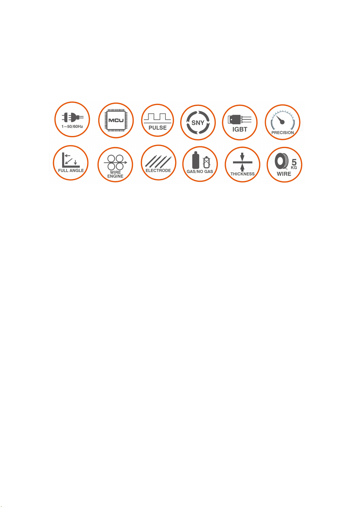
Advantages
1. Adopt full-digital signal processing system.
2. Rich in functions , delivers versatile welding process . embedding welding expert
database , specification match automatically via synergy technology .
3. Suitable to weld a broad range of materials like
Aluminum-magnesium ,Aluminium-silicon , Carbon steel ,stainless steel , alloy steel , etc .
4. Applicable for stainless steel wire , flux cored wire , Aluminum-magnesium
wire ,Aluminium-silicon wire , acid electrode rod , alkaline electrode rod , fiber electrode rod
5. Wide range of output current that suitable to weld different thickness of metal plate .
6. Software programmed welding specification that unaffected by hardware
components , better consistency than analog inverter machines .
7. Higher control precision , low deviation , Time can be accurate to microsecond ,
current can be accurate to 0.1Amp . precise and smooth wire feeding ,
8. The use of decreased hardware components greatly reduced malfunctions , ensures
better stability and reliability .
9. Higher efficiency. The high speed pulse MIG welding increased efficiency by 30 %
against analog welding machine .
10. Able to weld in full angles and directions , dynamic response , deeper welding pool ,
better mechanical welding joint , minimum welding spatter and good-looking appearance of
welding joint . small heat output .stable and smooth arc length during welding.
11. The special 4T function is suitable for welding materials with good thermal
conductivity , excellent welding performance during arc initiating and ending.

- 6 -
12. Intelligent cooling fan, that switches to sleep mode automatically during no-load
condition , and prolong service life of welding machine . energy saving .
13. Intelligent saving of welding specification .
14. Can be connect to robot automatic welding equipment .
15. Usable for remote control welding torch
16. Big display window , simple control panel for easy operation .
17. Strong 4 rolls wire feeding engine . smooth and easy wire feeding .
1. Control panel
2. Negative polarity
3. Positive polarity
4. Gas -no gas adapter
5. MIG torch
6. earthing
7. Power switch
8. Gas in
9. Power input
10. Cooling fan
- 7 -
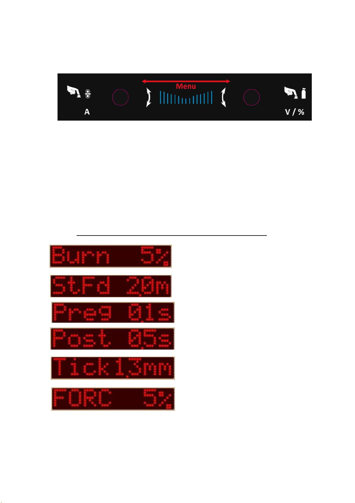
1. LED display.
2. Set of knobs - buttons for setting all available parameters:
a. left knob:
- rotation - welding current adjustment,
- pressing and holding - wire feed test,
b. right knob:
- rotation - voltage correction expressed in [V] or [%],
- short press - change units [V] or [%]. Press and hold - test gas flow.
Pressing both knobs simultaneously (but in order first right then left) causes entry
advanced menu devices. A detailed description can be found later in the manual in
chapter "Advanced menu".
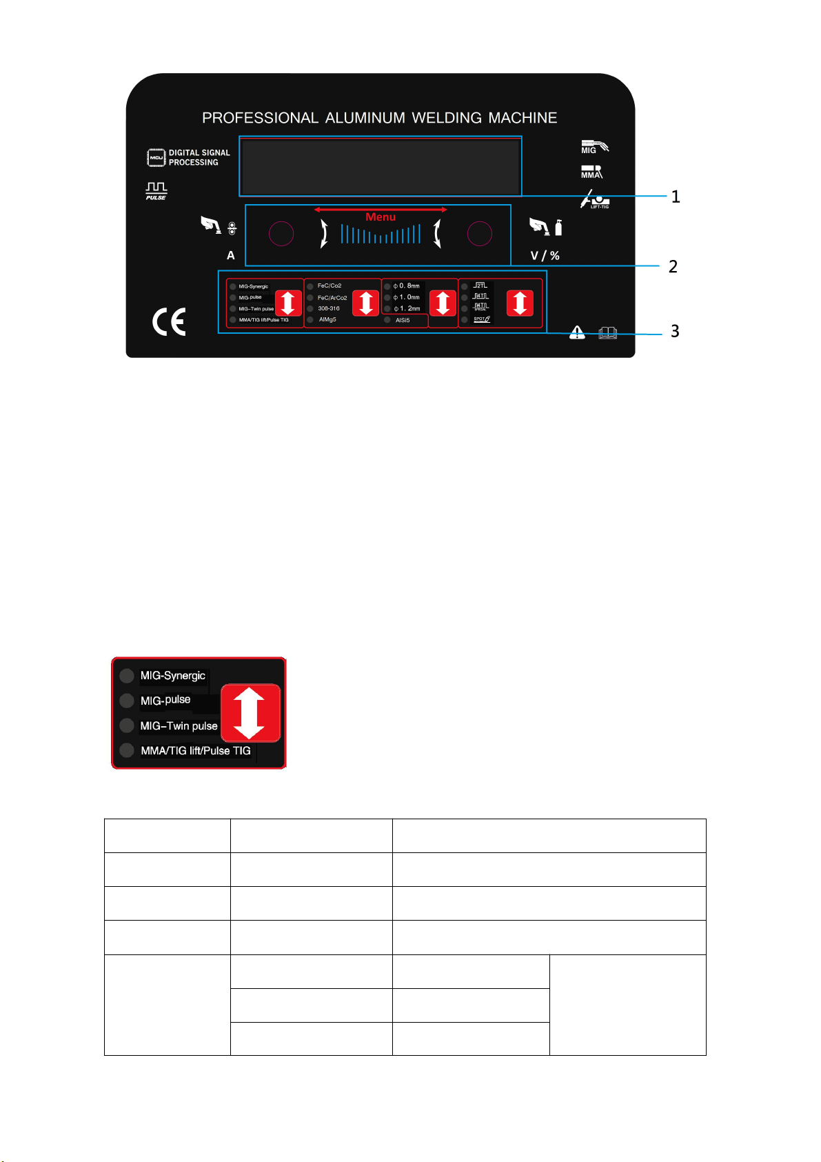
3. Quick selection menu:
Choice of welding method.
Mold
DISPLAY
Description
MIG
SNNC MIG
Synergic MIG-MAG welding
MIG pulse
PULSE MIG
Synergic MIG welding with single pulse
MIG Twin pulse
TWIN PULSE
Synergic MIG welding with double pulse
MMA/TIG LIFT
MMA MODE
MMA welding
Detailed selection on
control panel
TIG MODE
TIG welding
PULSE TIG
TIG pulse welding

- 8 -
selection of materials
items
materials
wire diameter
description
FeC/Co2
Fe CO2
0.8/1.0mm
Welding of carbon steels by the MAG method
CO2 shield.
FeC/ArCo2
Fe Ar82
0.8/1.0mm
Welding of carbon steels by the MAG method
Ar + CO2 gas mixture cover.
308-316
E308 Ar98
0.8/1.0mm
Welding of stainless steels
MIG method, in the shield
argon with an admixture of 2%
CO2, or in pure argon.
E316 Ar98
0.8/1.0mm
AlMg5
AlMg5 Ar
0.8/1.2mm
Welding aluminum and magnesium alloys,
MIG method, argon shielding.
AlSi5
AlSi5 Ar
0.8/1.2mm
Welding of aluminum alloys with silicon,
MIG method, argon shielding.
Selection of wire diameter available for a given method
Choice of control / control method
items
Display
description
2T
Mode 2T
Simple two-act
4T
Mode 4T
Normal four-bar
Special 4T
Mode S4T
Special four-cycle hot start and
final current
Mode S2T
Special two-step hot start and
final current.
SPOT
Mode SPOT
Normal spot welding.
Mode SPOT
Cyclic spot welding
- 9 -
ADVANCED MENU AND SETTINGS
Advanced menu - method selection.
Pressing both knobs simultaneously (but in order first right then left) causes entry
advanced menu devices.
Then the display will show the symbol of the currently set welding method.
By turning the right rotary knob you can select the desired welding method e.g. Pulse
TIG which is not available in quick selection menu.
After selecting a given method, turn the left knob to select the desired parameter and set
the right one value.
After about 10 seconds of inactivity, the device remembers the current settings and exits
automatically from the advanced menu, or earlier by pressing the right rotary knob.
Settings options.
After selecting the desired welding method, select or set other available parameters.
This can be done using the quick selection buttons or in the advanced menu.
The selection of a given parameter / function in the advanced menu is made with the left
rotary knob and the value for this parameter / function with the right rotary control.
The advanced menu of the device offers many detailed settings.
Burn height (burn back time).
Wire access speed (soft start).
Gas flow time before welding.
Gas flow time after welding.
Welded material thickness. The available
adjustment range is different for individual
materials and selected wire diameter.
For MIG welding (SYNC MIG) this is an
inductance correction.
For MIG Pulse and MIG 2-Pulse welding
(Pulse MIG and Twin Puls) this is correction
of peak current (first) amplitude.This is the Arc Force value for MMA welding
- 10 -
Pulsation frequency when welding with
double pulse MIG 2-Pulse.
Double pulse balance for double pulse
welding
Peak current amplitude when welding with
double pulse
Correction of the peak voltage (arc length)
when welding with
double pulse.
Correction of the voltage (arc length) of the
base current when welding with double pulse.
Transition time between two currents (current fall
time).
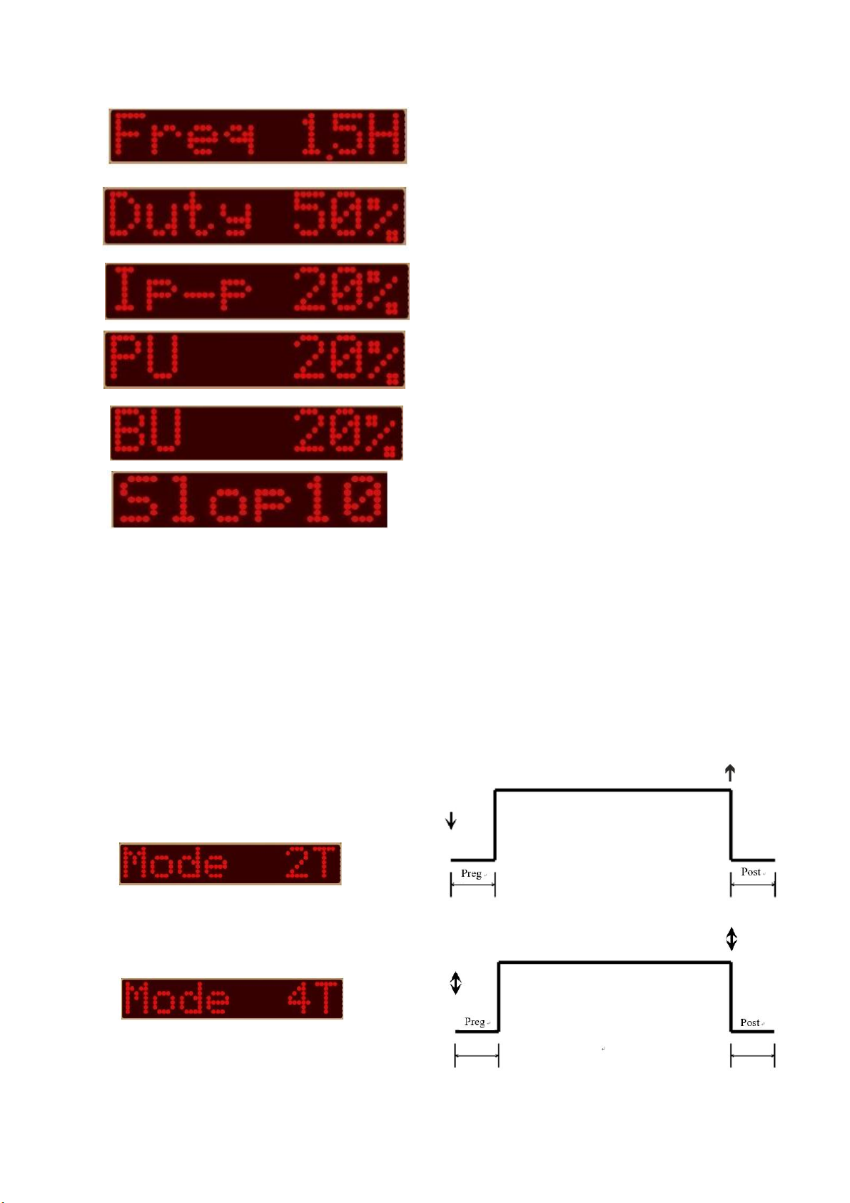
Device and current control options through a combination of pressing / releasing the
handle button MIG.
↓ - pressing the button on the work handle.
↑ - releasing the button on the work handle.
↨ - pressing and releasing the button on the
work handle.
Two-act - pressing the button initiates
gas flow and welding current, release
button turns off welding current
Four tact - pressing and releasing
MIG torch button initiates outflow
gas and welding current. Press again
and releasing the button turns the power off
welding

- 11 -
A special two-act with Hot Start and
final current (filling)
crater).
Pressing the MIG torch button initiates the flow of gas and hot start current to the set
Hot I values, which lasts according to the set Hot time.
After the time Hot t has elapsed, the current drops to the "normal" welding current. Duration
of the current decreaseis the same as the Slop position.
By releasing the button on the TIG torch, the welding current drops to the final current
End I. The duration of the current drop is the same as set in the Slop position.
The value of the final current is set in the End I position and its duration in the End position t.
After End time t arc goes out.
Remember that the slop fall time is identical at the beginning and end of the cycle.
Special four-bar with Hot Start and
final current (filling)
crater).
Pressing the button on the MIG handle
initiates gas leaks and Hot Start current to the
set Hot I value, which lasts as long as the handle button is pressed MIG. Releasing the
button causes the current to drop to the "normal" welding current.
The duration of the current drop is the same as set in the Slop position.
Pressing the MIG torch button again starts the welding current drop to the current value
End End I. The duration of the current drop is the same as set in the Slop position.
The final current (crater filling) End I lasts as long as the button on the MIG handle is
pressed.
Releasing the button extinguishes the arc.
Remember that the Slop current fall time is identical at the beginning and end of the cycle
Normal spot welding.
Pressing the MIG torch button initiates
gas flow and welding current start.
The welding current lasts as long as it is
set to position Sptt.
Cyclic spot welding.
Pressing the MIG torch button causes
welding current start. The welding current lasts as long as
is set to Sptt. Then the arc goes out and the stop is
stopped.
The break time is adjustable and can be 0.1 ÷ 25.5
seconds. After the set time has elapsed Stop time, device
again will start welding.
Welding-break cycle, welding-break cycle ...it lasts as long
as the button is pressed MIG torch.
Releasing the button ends the cycle.

- 12 -
Storing and recalling settings.
The device has 36 memory channels on which the user can save and recall any
settings.
1. To save the settings, press the two knobs simultaneously and enter the menu
Advanced.
2. Turn the left rotary knob to reach the Save position.
3. Set the channel number from 0 to 35 by turning the right rotary knob.
4. Press and hold the right rotary knob - the display should show SaveData
confirming that the settings have been saved to the selected channel.
1. To recall saved settings, simultaneously press both knobs to enter the menu
Advanced.
2. Turn the left rotary knob to reach the Load position.
3. Turn the right rotary control (7) to select the desired channel number on which the settings
are saved.
Note: The right rotary knob must also be turned if it is displayed in Load position immediately
desired channel number (i.e. change the channel number and then return to it).

- 13 -
USE
Connection
Before connecting this device to the mains, check the voltages, number of phases and
frequency.
Power supply voltage parameters are given in the chapter with technical data of this manual
and on the plate rated device.
Check the connections of the device's ground wires to the mains.
Make sure the mains can provide coverage of the input power requirement for this
the device under normal operating conditions.
The fuse size and power cord parameters are listed in the technical data of this manual.
The supply network should have stable voltage. Cross section of power cables
it should be not less than 2.5 mm.
Connect devices without power plugs according to the following instructions.
Connection and replacement of the power cord and plug should be made
qualified electrician
The yellow-green insulated wire is grounded and should always be connected to
socket marked with the earth symbol, regardless of whether we are dealing with 230 V
power supply or 400 [V].
Fitting welding cables - MIG / MAG.
ATTENTION! Before any activities carried out on the device pull the plug out of
the power socket.
1. Make sure that the device is not connected to the mains.
2. Check whether the earth lead is terminated with a pinch or screw clamp.
3. Connect the ground cable plug to the output socket on the front panel in correct polarity,
press and turn. Too loose a plug connection causes premature
burning of the plug and socket. We usually connect the ground cable in the MIG-MAG
method to the "-" socket. When using the so-called self-shielding wires ground wire is
connected to the "+" socket. The polarity change is made by switching the built-in plug to
second socket.
NOTE - THE POLARIZATION CHANGE PLUG MUST BE FIXED TO ONE OF THE
SOCKETS - THIS IS NECESSARY TO CLOSE THE CURRENT CIRCUIT.
4. Before installing the welding cable, make sure that the correct armor is installed
leading to the right diameter and type of wire. For ease of use leading armors, mark them
with appropriate colors. For wire with a diameter of 0.6 ÷ 0.8 mm, it has blue, for wire with a
diameter of 1.0 ÷ 1.2 mm, red, and for a wire with a diameter 1.6 mm, yellow. For welding
alloy steel and aluminum, we use Teflon armor. Down welding low-carbon steel, low-alloy
steel, copper, bronze, etc., spiral armor is used metal. Remember to equip the welding gun
with a contact tip suitable for grade and diameter of the wire.
5. Insert the "euro-plug" welding lead plug into the socket (Euro socket) located on
front panel of the welding machine, then tighten the nut by hand until it stops.
Installation of the wire
1. Ensure that the rollers installed in the power package match the type and diameter
introduced wire. If the roller groove differs with the diameter of the wire, adjust the groove,
by turning or replacing the roller. For steel wires, rolls with grooves should be used V, and
for aluminum wires with U-shaped grooves.
2. Place the wire spool on the spool attachment mechanism, paying attention to the direction
the unwinding of the wire was consistent with the direction of the wire's entry into the power
unit.
3. Lock the spool against falling by tightening the nut on the spool body.
4. The end of the wire wound on the spool should be straightened or cut off the bent section,
then sawn off, so it's not sharp.

- 14 -
5. To enable wire insertion in the feeder, release the pressure of the feed rollers.
6. Insert the end of the wire into the guide at the back of the feeder and route it over
with drive rollers and insert into the guide pipe into the welding gun.
7. Push the wire into the grooves of the drive rollers by tightening
pressure.
8. Remove the gas nozzle and unscrew the contact tip.
9. Turn on the device.
10. Unroll the handle so that it is in a straight line, then
press
button on the handle or control panel (wire feed) up to
when the wire appears in the outlet (approx. 20 mm),
release button.
11. Screw on the contact tip, install the gas nozzle.
12. Adjust the feed roller pressure by turning the knob
pressing. Too low downforce will cause slipping
the drive roller. Too high clamping force increases the feed resistance and deformation
wire, which can result in cutting.
Shielding gas connection.
1. A cylinder with suitable protective gas should be placed on the semi-automatic machine
shelf (if present) or next to it wall and secure it against falling over, fastening it to the bracket
with a chain.
2. Remove the protective cap and unscrew the cylinder valve for a moment to remove any
pollution.
3. Mount the regulator so that the pressure gauges are in a vertical position.
4. Connect the semi-automatic machine with the cylinder (outlet from the regulator with the
welding nozzle) with a suitable hose. Connection to shielding gas connection is located on
the back of the device.
5. Only unscrew the regulator valve before starting to weld. After welding, the valve
the cylinder should be turned off.
7. Avoid welding in the open or draft - a gust of air can disturb you shielding gas stream
and deprive liquid metal of protection.
Gas feeding .
When using the MIG(GMAW)welding process (solid wire) a shielding gas
is required . MAG welding shall be conducted using mixed gas . Mixing
of two gas (OC2 and Argon ) shall be performed with a gs mixer to
avoid uneven mixed gas .
1.A stainless steel hose clamp is recommended to ensure a leak-proof
connection. Using a secured GMAW shielding gas cylinder, slowly
open them.Close the cylinder valve while standing off to the side of the
value. This will remove any debris that may be around the valve
®ulator seat area.
2.Install the regulator and tighten with a wrench.
3.Connect the gas hose to the outlet of the regulator, and tighten with a
wrench.
4.Connect the other end of the gas hose to the “Gas Connector” on the
rear panel of the welder. (See image on previous page) A stainless steel hose clamp is
recommend to ensure a leak-proof connection.
5. Be sure the gas value on the torch is closed, and slowly open the cylinder value to the
fully open position.
6.Connect the ground clamp to your work piece.
7. Plug the power cable into the appropriate outlet, and turn switch to the “ON” position.
The power LED. light should illuminate.
8.Set the “Adjustment Switched” to the desired voltage.
You are now ready to begin MIG Welding
- 15 -
Selecting Wire Types
For thin metals, use a smaller diameter wire. For thicker metal use a larger wire and a
larger machine. See machine recommendations for welding capacity.
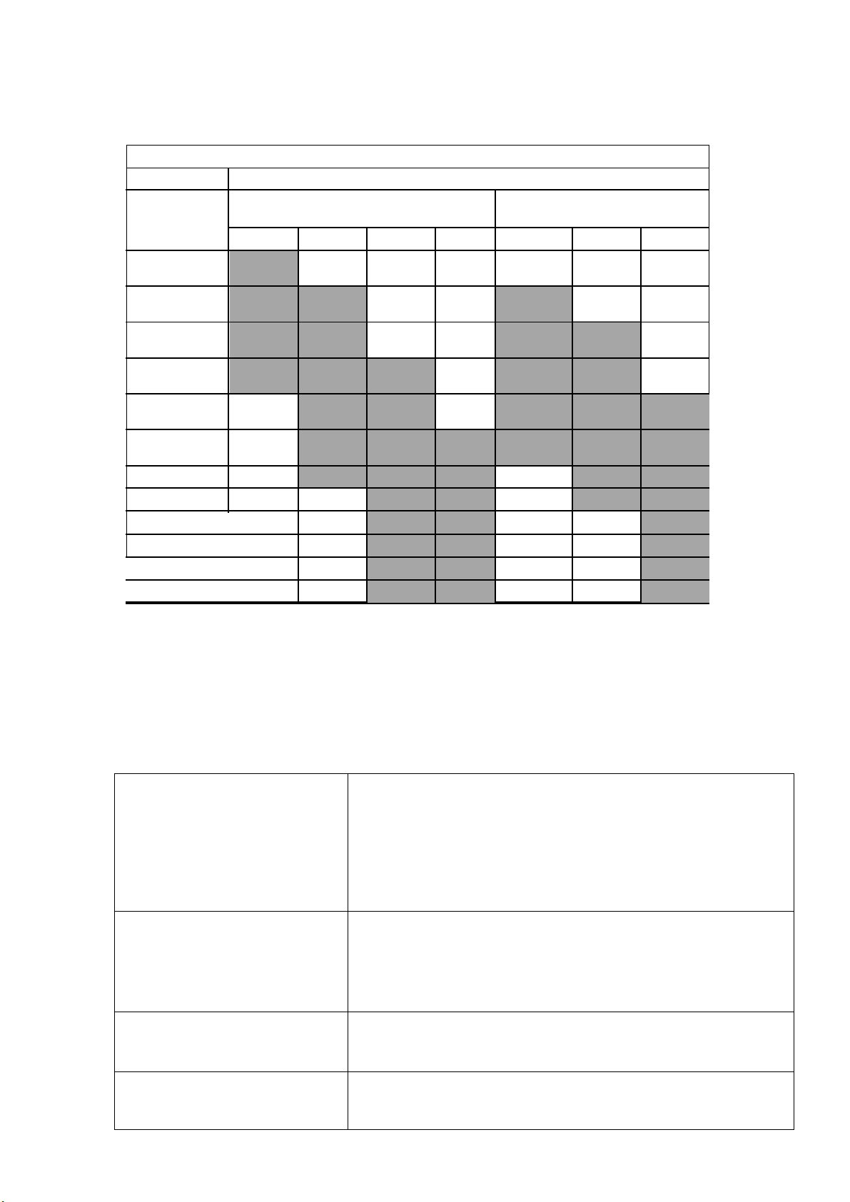
Welding Wire Thickness Chart
RECOMMENDED WIRE SIZES
MATERIAL
MIG SOLID WIRE
GASLESS FLUX-CORED
WIRE
THICKNESS
024”
030”
035”
045”
030”
035”
045”
24Gauge(025
)
22Gauge(031
)
20Gauge(037
)
18Gauge(050
)
16Gauge(063
)
14Gauge(078
)
1/8”(125)
3/16”(188)
1/4”(25)
5/16”(313)
3/8”(375)
1/2”(5)
Multi-pass welding or a beveled joint design may be required on material thickness
3/16” and Greater depending on your welding machine’s amperage capability.
Use the correct wire type for the base metal being welded. Use stainless steel wires for
stainless steel, aluminum wires for aluminum, and steel wires for steel. For steel , there are
two common wire types. Use an AWS classification ER70S-3 for all purpose, economical
welding. Use ER70S-6 wire when more deoxidizers are needed for welding on dirty or rusty
steel.
Solid Carbon-Steel ER 70S-6
●Must be used with CO2 or 75% Argon /25% (C-25) shielding gas
●CO2 gas is economical and Provides deeper penetration
●75% Argon/25% CO2 has less spatter and a better bead
appearance
●Indoor use with no wind
● For auto body and manufacturing Fabrication
●Welds thinner materials(22 gauge) than flux cored wires
Flux Cored/Carbon-steel E71T-11
●NO shielding gas required
●Excellent for outdoor or windy Conditions
●For dirty ,rusty, or painted Materials
●Hotter than solid wires
●Welds to 18 gauge material and thicker
Aluminum ER4043
●Must be used with Argon Shielding gas
●Recommended to me used withSpool gun for best results
●Harder wire for stronger welds And easier feeding
Stainless Steel ER 308L
●Must be used with Trimix (Helium/argon/CO2 or sprayShielding
gas
●Used for 301,302,304,305,and 308 stainless based materials

- 16 -
Holding and Positioning Welding Gun
WELDING WIRE IS ENERGIZED WHEN GUN TRIGGER IS PRESSED, BEFORE
LOEERING HELMET AND PRESSING TRIGGER,BE SURE WIRE IS NO MORE THAN 1/2
IN (13 MM)PAST END OF NOZZLE,AND TIP OF WIRE
IS POSITIONED CORRECTLY ON SEAM.
1. Hold Gun and Control Gun Trigger
2. Work-piece
3. Work Clamp
4. Electrode Extension (MMA-out)1/4 To 1/2 in (6 To
13 mm)
5. Cradle Gun and Rest Hand on Work-piece.
Practical recommendations for MIG / MAG welding.
Butt welds in the upright position should be carried out using the "push" technique for thin
elements and "pull" technique for thicker elements. Vertical butt joints for thin elements
should be done from top to bottom. Fillet welds in the lateral position should be carried out
using the technique "push", but taking into account the additional inclination of the welding
gun in the perpendicular plane for welding direction. When filling wide grooves in a
downward or vertical position, the end of the handle should be transverse swinging
movements. Welding gun during welding should be guided at the right angle in relation to
the elements to be welded - angle too large tilting may cause air to be sucked into the liquid
metal pool (handle angle from plumb should be ≤ 10 °). Long arc welding reduces the depth
of penetration - the weld is wide and flat, and welding is accompanied by increased spatter.
Short arc welding (at the same current density) increases the penetration depth - the weld is
narrower and the material spatter becomes smaller. Welding speed is the result parameter
at given current and arc voltage, and maintaining proper weld bead shape and speed
welding is to be even slightly changed, current or voltage should be changed accordingly
arc. The increase in welding speed makes the weld narrower and the penetration depth
decreases, and at further growth appear flooding of the face.The fastest welding speeds,
without flooding, can be done obtained by increasing the free electrode outlet and tilting the
object from top to bottom or tilting torch in the welding direction. Low welding speeds
increase the penetration depth, face width and head height.Inductance also affects the
shape of spins and the amount of spatter. Higher inductance (soft arc) causes a wider weld
pool and less splashes. In contrast, lower inductance produces a stable, focused arc.
MMA welding
The device described in this manual has the option of welding with coated electrodes
hot melt. It has two modes to optimally adjust the parameters to the type of electrode.
Cc mode for rutile, basic and acid electrodes, and Cp for cellulose electrodes.
In addition, you can adjust the Arc-force, the value and duration of the Hot-start function and
use the VRD function increasing safety during welding works.
Recommended welding current, polarity, drying requirements are usually given by
electrode manufacturers on their packaging.
Connect the welding leads to the current sockets (plus and minus).
Connect the earth lead to the workpiece, insert the electrode into the electrode lead
To avoid splashes during welding and to obtain a good quality weld, should be used
recommendations given by the electrode manufacturer: welding current, welding positions,
time and temperature drying. This is particularly important when using electrodes with a
basic coating or acid (EB, EA)
The basic parameters of the MMA welding process are:
- welding current,
- welding speed,
- thickness, type of electrode and material to be welded.
The amount of current is regulated so that the arc can ignite confidently, and during welding
was even and stable.
For example, the "Pink 6012" electrode needs: 2.0 mm 40 ÷ 60 A / 2.5 mm 50 ÷ 70 A
/ 3.25 mm 70 ÷ 110 A / 4.0 mm 110 ÷ 160 A / 5.0 mm 160 ÷ 220 A.

- 17 -
TIG LIFT welding
The device described in this manual can be used for TIG LIFT welding.
To do this, purchase a handle designed for this method - it is equipped with a mechanical
handle protective gas valve placed in the handle.
To TIG LIFT welding:
Insert the welding cable plugs into their respective sockets and lock them (earth clamp to
(+), TIG torch to (-)).
Connect the gas hose of the TIG torch directly to the gas outlet of the gas regulator
shielding (ARGON gas).
Connect the ground clamp to the workpiece.
Check the condition of the tungsten electrode.
Insert the plug of the mains cable into the mains socket.
Switch on the power supply to the device using the power switch.
Select the TIG or Pulse TIG function on the control panel.
Set the required welding parameters.
Unscrew the valve on the protective gas reducer and the valve on the TIG torch, this
will cause flow shielding gas.
The arc strikes by rubbing the non-fusible electrode on the workpiece.
MAINTENANCE
The following operation involving maintenance requires sufficient professional
knowledge on electric aspect and comprehensive safety knowledge . Operators
should be holders of valid qualification certificates which can prove their skills and
knowledge . Make sure the input cable of the machine is cut off from the electricity
unity before uncovering the welding machine
(1) Check periodically whether inner circuit connection is in good condition(esp
plugs) .Tighten the loose connection .if there is oxidization , remove it with sandpaper
and then reconnect .
(2) Keep hands ,hair and tools away from the moving parts such as the fan to avoid
personal injury or machine damage .
(3) Clean the dust periodically with dry and clean compressed air .if welding environment
with heavy smoke and pollution , the machine should be cleaned daily . The pressure of
compressed air should be at a proper level in order to avoid the small parts inside the
machine to be damaged .
(4) Avoid rain , water and vapor instill the machine . if there is , dry it and check the
insulation with equipment (including that between the connection and that between the
connection and the enclosure ) only when there are no abnormal phenomena anymore ,
then the machine can be used
(5) Check periodically whether the insulation cover of all cable is in good condition . if there
is any dilapidation ,replace it .
(6) Put the machine into the original packing in dry location if it is not to be used for a long
time
(7) Check the inter circuit of welding machine regularly and make sure the cable circuit is
connected correctly and connectors are connected tightly (especially insert connector
and components ) if scale and loose are found , please give a good polish to them , then
connect then again tightly
(8) The machine works accumulates for every 300 hours ,the electric carbon brush and
armature rectifier should be polished , the reducer should be cleaned and lubricator
should be added to the turbo and bearing .
(9) Welding cables : regularly inspect their connections
(10) Torch: regularly clean the contact tip and shroud to remove spatter that will eventually
disturb the gas flow of wire feeding . spraying the tip and shroud with anti-spatter spray
can reduce the build up of spatter . replace the tip periodically to maintain a good
electrical contact between the tip and the wire . blow clean dry air through the torch liner
from time to time to ensure the wire passes freely though it . if this has does not work,
the liner should be replaced .

Imported & Distributed by
Phone:
Email:
Website:
0800 699 353
www.prolineindustrial.co.nz
Table of contents
Popular Welding System manuals by other brands

Thermal Dynamics
Thermal Dynamics DRAG-GUN 38 instruction manual

BOC
BOC Starpower 304 owner's manual

Magmaweld
Magmaweld RS 350 MK user manual

Lincoln Electric
Lincoln Electric PRO-CUT 60 SVM104-A Service manual

WeldCorp
WeldCorp MULTI PULSE PRO 240 Owner's operating manual

Hypertherm
Hypertherm HT2000 instruction manual


