Prology DVD-555 User manual

PROLOGY DVD-555
SERVICE MANUAL
V1.0
SPECIFICATION
Power requirement 12V DC car battery
(negative earth)
Operating temperature -10 +65
Stragetemperature -20 +70
Operational humidity 10% 80%
Atmospherepressure 860mbar 1060mbar
TABLE OF CONTENTS CAR DVD PLAYER
1.GENERAL
2.BLOCKDIAGRAM
3.ELECTRICAL TROUBLE SHOOTING GUIDE
4.PRINTED CIRCUIT
5.ELECTRICAL PARTS LIST
All manuals and user guides at all-guides.com
all-guides.com

PRODUCT SAFETY SERVICING GUIDELINES FOR VIDEO PRODUCTS
CAUTION: DO NOT ATTEMPT TO MODIFY THIS PRODUCT IN ANY WAY AND NEVER SUBJECT: X-RADIATION
PERFORM CUSTOMIZED INSTALLATIONS WITHOUT MANUFACTURER'S APPROVAL.
NAUTHORIZED MODIFICATIONS WILL NOT ONLY VOID THE WARRANTY, BUT MAY LEAD TO 1.BE SURE PROCEDURES AND INSTRUCTIONS TO ALL SERVICE PERSONNEL COVER THE
YOUR BEING LIABLE FOR ANY RESULTING PROPERTY DAMAGE OR USER INJURY. SUBJECT OF X-RADIATION. THE ONLY POTENTIAL SOURCE OF X-RAYS IN CURRENT T.V.
RECEIVERS IS THE PICTURE TUBE. HOWEVER, THIS TUBE DOES NOT EMIT X-RYS WHEN THE
SERVICE WORK SHOULD BE PERFORMED ONLY AFTER YOU ARE THOROUGHLY FAMILIAR HIGH VOLTAGE IS AT THE FACTORY SPECIFIED LEVEL. THE PROPER VALUE IS GIVEN IN THE
WITH ALL OF THE FOLLOWING SAFETY CHECKS AND SERVICING GUIDELINES. TO DO APPLICABLE SCHEMATIC. OPERATION AT HIGHER VOLTAGES MAY CAUSE A FAILURE OF
OTHERWISE, INCREASES THE RISK OF POTENTIAL HAZARDS AND INJURY TO THE USER. THE PICTURE TUBE OR HIGH VOLTAGE SUPPLY AND, UNDER CERTAIN CIRCUMSTANCES,
MAY PRODUCE RADIATION IN EXCESS OF DESIRABLE LEVELS.
.WHILE SERVICING, USE AN ISOLATION TRANSFORMER FOR PROTECTION FROM A.C. LINE
SHOCK. 2. ONLY FACTORY SPECIFIED C.R.T ANODE CONNECTORS MUST BE USED
DEGAUSSING SHIELDS ALSO SERVE AS AN X-RAY SHIELD IN COLOR SETS,
SAFETY CHECKS ALWAYS RE-INSTALL THEM.
AFTER THE ORIGINAL SERVICE PROBLEM HAS BEEN CORRECTED, A CHECK SHOULD BE 3. IT IS ESSENTIAL THAT SERVICE PERSONNEL HAVE AVAILABLE AN ACCURATE AND
MADE OF THE FOLLOWING. RELIABLE HIGH VOLTAGE METER. THE CALIBRATION OF THE METER SHOULD BE CHECKED
PERIODICALLY AGAINST A REFERENCE STANDARD, SUCH AS THE ONE AVAILABLE AT YOUR
DISTRIBUTOR.
SUBJECT: FIRE & SHOCK HAZARD
4. WHEN THE HIGH VOLTAGE CIRCUITRY IS OPERATING PROPERLY, THERE IS NO
1. BE SURE THAT ALL COMPONENTS ARE POSITIONED IN SUCH A WAY AS TO AVOID POSSIBILITY OF AN ACCURATE AND RELIABLE HIGH VOLTAGE METER. THE CALIBRATION OF
POSSIBILITY OF ADJACENT COMPONENT SHORTS. THIS IS ESPECIALLY IMPORTANT ON THE METER SHOULD BE CHECKED PERIODICALLY AGAINST A REFERENCE STANDARD,
THOSE MODULES WITCH ARE TRANSPORTED TO AND FROM THE REPAIR SHOP.SUCH AS THE ONE AVAILABLE AT YOUR DISTRIBUTOR.
2. NEVER RELEASE A REPAIR UNLESS ALL PROTECTIVE DEVICES SUCH AS INSULATORS, 5. WHEN TROUBLESHOOTING AND MAKING TEST MEASUREMENTS IN A PRODUCT WITH A
BARRIERS, COVERS, SHIELDS, STRAIN RELIEFS, POWER SUPPLY CORDS, AND OTHER PROBLEM OF EXCESSIVE HIGH VOLTAGE AVOID BEING UNNECESSARILY CLOSE TO THE
HARDWARE HAVE BEEN REINSTALLED PER ORIGINAL DESIGN. BE SURE THAT THE SAFETY PICTURE TUBE AND THE HIGH VOLTAGE SUPPLY DO NOT OPERATE THE PRODUCT LONGER
PURPOSE OF THE POLARIZED LINE PLUG HAS NOT BEEN DEFEATED. THAN IT IS NECESSARY TO LOCATE THE CAUSE OF EXCESSIVE VOLTAGE.
3. SOLDERING MUST BE INSPECTED TO DISCOVER POSSIBLE COLD SOLDER JOINTS, 6. REFER TO HV. B+ AND SHUTDOWN ADJUSTMENT PROCEDURES DESCRIBED IN THE
SOLDER SPLASHES OR SHARP SOLDER POINTS. BE CERTAIN TO REMOVE ALL LOOSE APPROPRIATE SCHEMATIC AND DIAGRAMS(WHERE USED).
FOREIGN PARTICLES.
4. CHECK FOR PHYSICAL EVIDENCE DF DAMAGE OR DETERIORATION TO PARTS AND SUBJECT: IMPLOSION
COMPONENTS, FOR FRAYED LEADS AND DAMAGED INSULATION (INCLUDING A.C.
CORD), AND REPLACE IF NECESSARY FOLLOW ORIGINAL LAYOUT, LEAD LENGTH AND 1. ALL DIRECT VIEWED PICTURE TUBES ARE EQUIPPED WITH AN INTEGRAL IMPLOSION
DRESS. PROTECTION SYSTEM, BUT CARE SHOULD BE TAKEN TO AVOID DAMAGE DURING
INSTALLATION, AVOID SCRATCHING THE TUBE. IF SCRATCHED REPLACE IT.
5. NO LEAD OR COMPONENT SHOULD TOUCH A RECEIVING TUBE OR A RESISTOR RATED
AT 1 WATT OR MORE. LEAD TENSION AROUND PROTRUDING METAL SURFACES MUST BE 2. USE ONLY RECOMMENDED FACTORY REPLACEMENT TUBES.
AVOIDED.
SUBJECT: TIPS ON PROPER INSTALLATION
6. ALL CRITICAL COMPONENTS SUCH AS FUSES. FLAMEPROOF RESISTORS, CAPACITORS,
ETC. MUST BE REPLACED WITH EXACT FACTORY TYPES, DO NOT USE REPLACEMENT
COMPONENTS OTHER THAN THOSE SPECIFIED OR MAKE UNRECOMMENDED CIRCUIT 1. NEVER INSTALL ANY PRODUCT IN A CLOSED-IN RECESS. CUBBYHOLE OR CLOSELY
MODIFICATIONS. FITTING SHELF SPACE, OVER OR CLOSE TO HEAT DUCT, OR IN THE PATH OF HEATED AIR
FLOW.
7. AFTER RE-ASSEMBLY OF THE SET, ALWAYS PERFORM AN A.C. LEAKAGE TEST ON ALL
EXPOSED METALLIC PARTS OF THE CABINET, (THE CHANNEL SELECTOR KNOB, ANTENNA 2. AVOID CONDITIONS OF HIGH HUMIDITY SUCH AS: OUTDOOR PATIO INSTALLATIONS
TERMINALS. HANDLE AND SCREWS) TO BE SURE THE SET IS SAFE TO OPERATE WITHOUT WHERE DEW IS A FACTOR, NEAR STEAM RADIATORS WHERE STEAM LEAKAGE IS A FACTOR,
DANGER OF ELECTRICAL SHOCK. DO NOT USE A LINE ISOLATION TRANSFORMER DURING ETC.
THIS TEST, MAKE SURE TO USE AN A.C. VOLTMETER. HAVING 5000 OHMS PER VOLT OR
MORE SENSITIVITY, IN THE FOLLOWING MANNER; CONNECT A 1500 OHMS 10 WATT 3. AVOID PLACEMENT WHERE DRAPERIES MAY OBSTRUCT REAR VENTING. THE CUSTOMER
RESISTOR, PARALLELED BY A.15 MFD. 150V A.C. TYPE CAPACITOR BETWEEN A KNOWN SHOULD ALSO AVOID THE USE OF DECORATIVE. SCARVES OR OTHER COVERINGS WHICH
GOOD EARTH GROUND (WATER PIPE, CONDUIT, ETC.) AND THE EXPOSED METALLIC PARTS, MIGHT OBSTRUCT VENTILATION.
ONE AT A TIME. MEASURE THE A.C. VOLTAGE ACROSS THE COMBINATION OF 1500 OHM 4. WALL AND SHELF MOUNTED INSTALLATIONS USING A COMMERCIAL MOUNTING KIT,
RESISTOR AND 15 MFD CAPACITOR. REVERSE THE A.C. PLUG AND REPEAT A.C. ANY MUST FOLLOW THE FACTORY APPROVED MOUNTING INSTRUCTIONS. A PRODUCT
VOLTAGE MEASUREMENTS FOR EACH EXPOSED METALLIC PART. VOLTAGE MEASURED MOUNTED TO A SHELF OR PLATFORM MUST RETAIN ITS ORIGINAL FEET (OR THE
MUST NOT EXCEED 75 VOLTS R.M.S. THIS CORRESPONDS TO 0.5 MILLIAMP A.C. ANY EQUIVALENT THICKNESS IN SPACERS). TO PROVIDE ADEQUATE AIR FLOW ACROSS THE
VALUE EXCEEDING THIS LIMIT CONSTITUTES A POTENTIAL SHOCK HAZARD AND MUST BE BOTTOM. BOLTS OR SCREWS USED FOR FASTENERS MUST NOT TOUCH ANY PARTS OR
CORRECTED IMMEDIATELY. WIRING. PERFORM LEAKAGE TEST ON CUSTOMIZED INSTALLATIONS.
5. CAUTION CUSTOMERS AGAINST THE MOUNTING OF A PRODUCT ON SLOPING SHELF
OR A TILTED POSITION, UNLESS THE PRODUCT IS PROPERLY SECURED.
6. A PRODUCT ON A ROLL-ABOUT CART SHOULD BE STABLE ON ITS MOUNTING TO THE
CART CAUTION THE CUSTOMER ON THE HAZARDS OF TRYING TO ROLL A CART WITH
SMALL CASTERS ACROSS THRESHOLDS OR DEEP PILE CARPETS.
7. CAUTION CUSTOMERS AGAINST THE USE OF A CART OR STAND WHICH HAS NOT BEEN
GOOD EARTH GROUND LISTED BY UNDERWRITERS LABORATORIES, INC. FOR USE WITH THEIR SPECIFIC MODEL OF
SUCH AS THE WATER TELEVISION RECEIVER OR GENERICALLY APPROVED FOR USE WITH TV'S OF THE SAME OR
PIPE, CONDUIT, ETC. LARGER SCREEN SIZE.
8. CAUTION CUSTOMERS AGAINST THE USE OF EXTENSION CORDS. EXPLAIN THAT A
FOREST OF EXTENSIONS SPROUTING FROM A SINGLE OUTLET CAN LEAD TO DISASTROUS
SUBJECT GRAPHIC SYMBOLS CONSEQUENCES TO HOME AND FAMILY.
The lightening flash with arrowhead symbol, within an equilateral
triangle, is intended to alert the user to the presence of uninsulated
"dangerous voltage" within the product's enclosure that may be of
sufficient magnitude to constitute a risk of electric shock to persons.
The exclamation point within an equilateral triangle is intended to alert
the user to the presence of important operating and maintenance
(servicing) instructions in the literature accompanying the appliance.
PLACE THIS PROBE
ON EACH EXPOSED
METAL PART
2
All manuals and user guides at all-guides.com

CAUTION : Before servicing the DVD covered by this service Electrostatically Sensitive (ES) Devices
data and its supplements and ADDENDUMS, read and Some semiconductor (solid state) devices can be
follow the SAFETY PRECAUTIONS NOTE : if unforeseen damaged easily by static electricity. Such components
circumstances create conflict between the following commonly are called Electrostatically Sensitive (ES) Devices.
servicing precautions and any of the safety precautions in Examples of typical ES devices are integrated circuits and
this publications, always follow the safety Precautions. some field effect transistors and semiconductor chip
Remember Safety First: components. The following techniques should be used to
help reduce the incidence of component damage
caused by static electricity.
General Servicing Precautions
1. Immediately before handling any emiconductor
1. Always unplug the DVD DC power cord from the DC component or semiconductor-equipped assembly, drain
power source before: off any electrostatic charge on your body by touching a
(1) Removing or reinstalling any component, circuit board, known earth ground. Alternatively, obtain and wear a
module, or any other assembly. commercially available discharging wrist strap device,
(2) Disconnection or reconnecting any internal electrical which should be removed for potential shock reasons
plug or other electrical connection. prior to applying power to the unit under test.
Caution : A wrong part substitution or incorrect polarity
installation of electrolytic capacitors may result in an 2. After removing an electrical assembly equipped with ES
explosion hazard. devices, place the assembly on a conductive surface
such as aluminum toil, to prevent electrostatic charge
2. Do not spray chemicals on or near this DVD or any of its buildup or exposure of the assembly.
assemblies.
3. Use only a GROUNDED-tip soldering iron to solder or
3. Unless specified otherwise in this service data, clean unsolder ES devices.
electrical contacts by applying an appropriate contact
cleaning solution to the contacts with a pipe cleaner, 4. Use only an anti-static solder removal device. Some
cotton-tipped swab, or comparable soft applicator. solder removal devices not classified a "anti-static" can
Unless specified otherwise in this service data, lubrication generate electrical charges sufficient to damage ES
of contacts is not required. devices.
4. Do not defeat any plug/socket B+ voltage interlocks with 5. Do not use freon-propelled chemicals. These can
which instruments covered by this service manual might generate electrical charge sufficient to damage ES
be equipped. devices.
5. Do not apply AC power to this DVD and/or any of its 6. Do not remove a replacement ES device from its
electrical assemblies unless all solid-state device heat protective package until immediately before you are
sinks are correctly installed ready to install it. (Most replacement ES devices are
.packaged with leads electrically shorted together by
6. Always connect test instrument ground lead to the conductive foam, aluminum foil, or comparable
appropriate ground before connection the test conductive material.)
instrument positive lead. Always remove the test
instrument ground lead last. 7. Immediately before removing the protective material
from the leads of a replacement ES device, touch the
protective material to the chassis or circuit assembly into
Insulation Checking Procedure which the device will be installed.
Disconnect the attachment plug trom the AC outlet and Caution : Be sure no power is applied to the chassis or
turn the power on. Connect an insulation resistance circuit, and observe all other safety precautions.
meter(500V) to the blades of the attachment plug. The
insulation resistance between each blade of the 8. Minimize bodily motions when handling unpackaged
attachment plug and accessible conductive parts (Note 1) replacement ES devices. (Normally harmless motion
should be more than 1M ohm. such as the brushing together of your clothes fabric or
the lifting of your foot from a carpeted floor can
Note 1 : Accessible Conductive Parts including Metal generate static electricity sufficient to damage an ES
panels, input terminals, Earphone jacks, etc. device.)
SERVICING PRECAUTIONS
3
All manuals and user guides at all-guides.com

16 PIN CON
POWER D8V
MCU
FPSW
REMOTR
ENCODER
B+ ACC
T9V 2CH 100mV
B+ ACC A9V A9V A12V B+ 4CH POWER OUT
2CH 1V 4CH 2V 4X25W
2CH LINE OUT 2V
A9V VDD-5V
P5V
2CH 1V
A5V 2CH DIGITALL AUDIO
A9V A12V
2CH 1V 2CH DVD REAR OUT
2V
LCD/KEY PCB
DV-100 BLOCK
DIAGRAM
MAIN
PCB
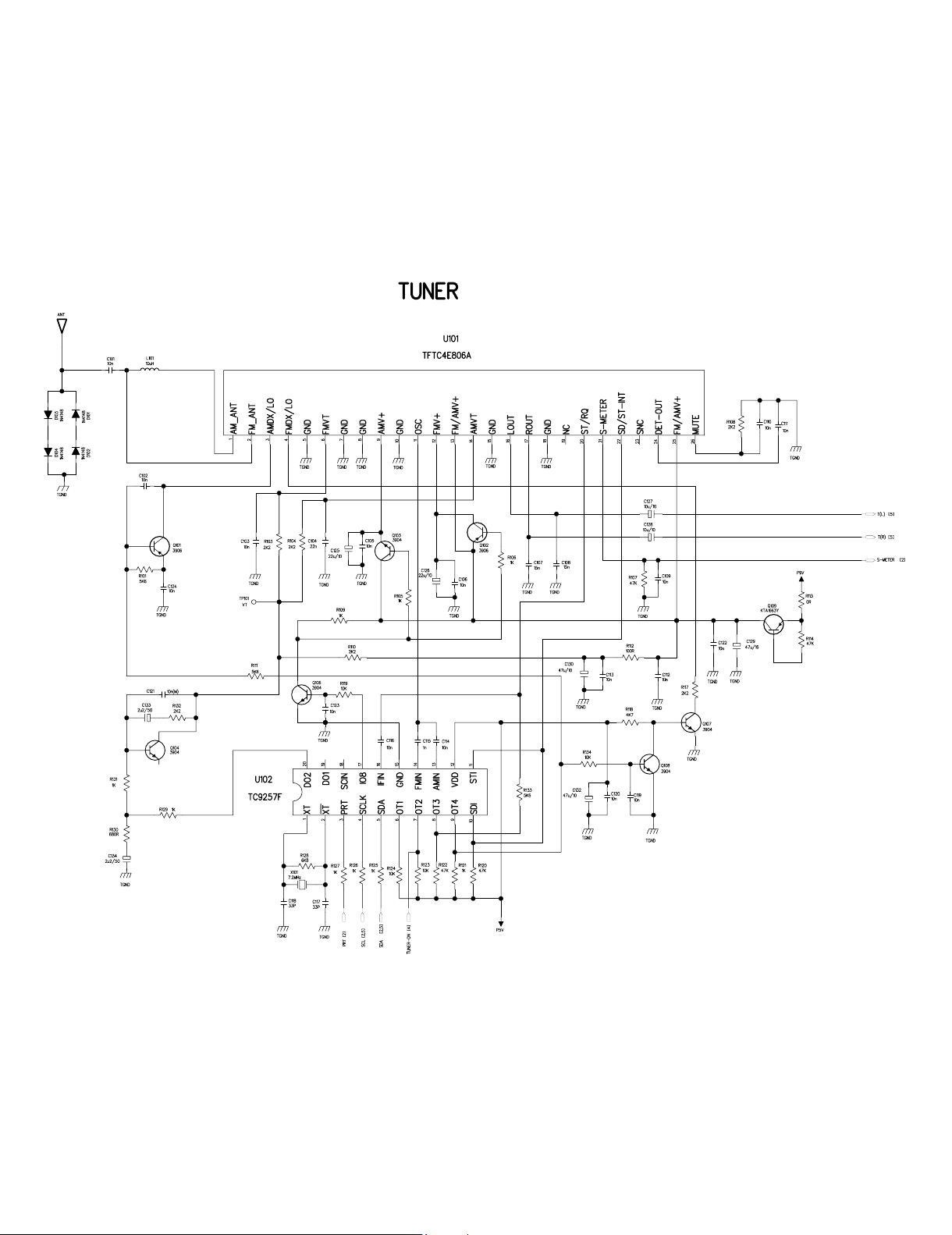
TUNER
FAE347
CDC
AUX-IN
PLL
TC9257
BA3121
BA3121
LCD
AUDIO DSP
TEA6320
LCD/KEY
DRIVER
UPD16431
PRE AMP
2X4558
MCU
TMP87CM21D
F
POWER
SUPPLY
POWER AMP
TDA7381
PRE AMP
4558
LEVEL
3V3 TO 5V
AUDIO
SW
4053
AUDIO D/A
CS4340
All manuals and user guides at all-guides.com

10PIN CON
POWER D12V D5V
DC12V LOAD MOTOER
DC1V8
DC3V3
DC5V 2CH CVBS
FOCUS TRACK
SLED
LOAD
DVD-C01 SC
SPINDER MOTOR
ATAPI INTERFACE
SHARP
HPD-50
RF-PREAMP
SP3721
MECHA
MOTOR
EPROM
29C011
ALI DSP
SERVO
M5705
DRIVER
BA5945
SDRAM
16M
DRIVER
BA6849 8M FLASH
29LV800
CIRRUS MPEG
CS98100
SDRAM
64M
VIDEO BP
FILTERS
EEPROM
AT24C02A
POWER
SUPPLY
24PIN CON
MCU
DG AUDIO
SW
All manuals and user guides at all-guides.com

APower Circuit abnormal (For main board)
Is the inout of Q419 DC 12V?
START
Check the fuse.
Is 40pin of U201 VDD-5V? Check Q401 ZD402 L401 and peripheral
components.
YES
NO
NO
Is 26pin of U201 DC 12V?
YES
Check ACC and ACC fuse.
Check ZD401 and peripheral components.
NO
Is the out of Q404 DC 12V?
YES
Check Q404,Q408
NO
Is the output of U404 DC 5V?
YES
Check U404 and peripheral components.
NO
Is the out of Q402 P12V?
YES
Check Q402 Q406 and peripheral
components.
NO
Is the out of U402 DC 8V?
YES
Check ZD439 and peripheral components.
NO
Is 2pin of U406 DC 3.3V?
YES
Check U406 and peripheral components.
NO
Is 2pin of U407 DC 1.8V?
YES
Check U407 and peripheral components.
NO
Normal
YES
All manuals and user guides at all-guides.com
all-guides.com

B Display abnormal (For main board)
START
Does the screen appear? Check if the 14pin voltage of DC8V?
Check if the 16pin voltage of DC5V?
Check the key board according to key schematic.
YES
NO
Is display normal? Check the key board according to key
schematic.
YES NO
Normal
YES
All manuals and user guides at all-guides.com

CIN/OUT abnormal (For main board)
The disc can’t be in
j
ected
Is 6pin of BA6951 DC 12V? Check L2
YES
NO
Is voltage between 5 and 10 pin of BA6951
DC 4.6V after eject-key being pressed?
1.Check CN401 at S&D board,connection between
it and MCU.
2.Check R204,BA6951.
YES
NO
Is voltage between 11 and 12 pin of J203 at
S&D board DC 4.5V? Check connection between main board and S&D
board.
YES
NO
Normal
YES
All manuals and user guides at all-guides.com

DLogo display abnormal (For S&D board(Servo and Decoder board))
Is voltage for CN401 normal? Check connection of main board and S&D
board.
NO
YES
No Logo display? Check S&D board.
NO
YES
Having picture,no color or color
disappeared during playback. Check decoder part and change Y101.
NO
YES
Normal
All manuals and user guides at all-guides.com

ERead disc abnormal (For S&D board)
Focus on? Refer to Focus abnormal.
NO
YES
DISC IN
Is laser normal? Refer to laser abnormal.
NO
YES
Does the disc turn? Refer to disc turn abnormal.
NO
YES
Can TOC be read? Refer to TOC abnormal.
NO
YES
Normal
All manuals and user guides at all-guides.com

FVideo abnormal (For S&D board)
Only Logo display Check the connection of U102 and ZR36776.
NO
YES
Having picture,no color or color
disappeared during playback. Check decoder part and change Y101.
YES
NO
Having picture,but picture
disappeared during playback. Check decoder part and change Y101.
YES
NO
Normal
All manuals and user guides at all-guides.com
all-guides.com

GAudio abnormal (For main board)
Is the rear channel normal? Refer to rear out abnormal
NO
YES
Is the front channel and
sbw channel normal? Refer to front out abnormal
NO
YES
Is the power amplifier normal? Check U301 and peripheral components
NO
YES
Normal
All manuals and user guides at all-guides.com

H Tuner abnormal (For main board)
Auto search abnormal
Is 13pin of U101 DC 9V?
Check P9V,if P9V is 9V,
Check Q110 Q115 and peripheral components.
If P9V is 0V,check according to main board power
schematic.
NO
YES
Is X101 oscilating? Check TC9257 X101 and peripheral components
NO
YES
Is 12pin of U101 9V at FM mode
and 0V at AM mode? Check 17pin of TC9257,Q103,Q108 and
peripheral components
NO
YES
Normal
Auto search normal
but audio abnormal
YES
Is 3,4,29,30 pin of U503 normal? Replace U503
NO
Check connection between 16,17 pin of
U101 and U503.
NO
YES
Normal
YES
RDS normal?
YES
Normal
Check U707 and peripheral components.
NO
All manuals and user guides at all-guides.com
All manuals and user guides at all-guides.com

All manuals and user guides at all-guides.com

All manuals and user guides at all-guides.com
all-guides.com

All manuals and user guides at all-guides.com

All manuals and user guides at all-guides.com

All manuals and user guides at all-guides.com

All manuals and user guides at all-guides.com
Other manuals for DVD-555
1
Table of contents
Other Prology Car Receiver manuals


 Installation/connections")


