Orion COBALT CO603 User manual

Coaxial Speaker MODEL
CO40
CO46
CO52
CO57
CO60
CO65
CO653
CO68
CO69
CO693
OWNER'S MANUAL
TM


TABLE OF CONTENTS
English . . . . . . . . . . . . . . . . . . . ..................................... 1
Français . . . . . . . . . . . . . . . . . . . .................................... 9
Español. . . . ................................................... 13
Deutsch . . . . . . . . . . . . . . . . . . . ................................... 17
Italiano. . . . ................................................... 21
Português . . . . . . . . . . . . . . . . . . . . . . . . . . . . . . . . . . . . ................ 25
Introduction. . . . . . . . . . . . . . . . . . . . . . . . . . . . . . . . . . . . ................ 1
Practice Safe Sound™. . . . . . . . . . . . . . . . . . . . . . . . . . . . . . . . . . . . . . . . . . . . 1
Installation. . . . . . . . . . . . . . . . . . . . . . . . . . . . . . . . . . ................... 2
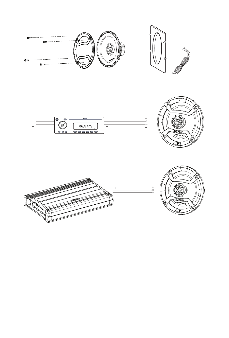
What’s in the Box . . . . . . . . . . . . . . . . . . . . . . . . . . . . . . . . . . . . . . . . . . . . . . . 2
Tools of the Trade . . . . . . . . . . . . . . . . . . . . . . . . . . . . . . . . . . . . . . . . . . . . . . . 2
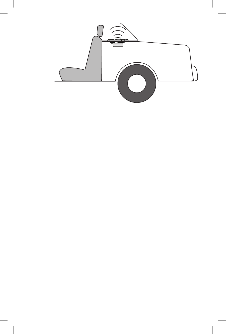
Finding Speaker Mounting Locations . . . . . . . . . . . . . . . . . . . . . . . . . . . . . . . 3
Door Mounting. . . . . . . . . . . . . . . . . . . . . . . . . . . . . . . . .............. 3
Rear Deck Mounting . . . . . . . . . . . . . . . . . . . . . . . . . . . . . . . . . . . . . . . . . 3
Step by Step Installation. . . . . . . . . . . . . . . . . . . . . . . . . . . . . . . . . . . . . . . . . . 4
Specifications. . . . . . . . . . . . . . . . . . . . . . . . . . . . . . . . . . . . . . . . . . . . . . . . . . . 6
Features . . . . ................................................... 6
Warranty . . . . . . . . . . . . . . . . . ............................. back cover
INTRODUCTION
Thank you for your purchase of ORION's Cobalt Coaxial Speakers. These
speakers offer renowned Orion excellence in every high performance
speaker system. The metalized PEI (Polyetherimide) dome tweeter can be
angled on a 360° axis for optimal imaging and sound quality. Designed for
OEM applications, the Cobalt coaxial speakers will fit standard 4”,5.25",6",
6.5" round and 4” x 6”,5" x 7",6” x 8”, 6" x 9"oval mounting locations.
PRACTICE SAFE SOUND™
Continuous exposure to sound pressure levels over 100dB may cause
permanent hearing loss. High powered automotive sound systems can
generate sound pressure levels in excess of 130dB. When playing your system
at high levels, please use hearing protection and prevent long term exposure.
Model Number: ____________________________
Serial Number: ____________________________
Date of Purchase: ____________________________
@2012 MD Audio Engineering-all rights reserved 1

2
INSTALLATION
The performance of the Cobalt coaxial speakers is directly proportional to the
quality of installation. Care taken during the installation process will be
rewarded with years of satisfying performance. If you are unsure about your
installation capabilities, please refer to your local Authorized ORION Dealer
for technical assistance. ORION dealers are trained professionals dedicated
to obtaining the maximum performance out of your ORION system. If
you decide to install this speaker system yourself, please read the entire
installation section before starting your installation.
TOOLS OF THE TRADE
Listed are the majority of the tools required to perform the installation.
Having the proper tools will make the installation much easier. Some of these
tools are required.
omarking pen needle nose pliers
owire crimpers oelectric drill
ovolt-ohm meter (opt.) wire strippers
o1/8" drill bit wire cutters
oassorted tin snips ohole saw arbor
oPhillips screwdriver
o43/4" (120mm) hole saw (5"Coaxial installation)
o51/2" (140mm) hole saw (6" Coaxial installation)
WHAT’S IN THE BOX
Included in this box are all the necessary mounting hardware and cables
for your basic installation. Listed below is a detailed list of the components
included in this system package.
Quantity Description
1 Installation and Operation Manual
1
1
Mounting template
2 Cobalt Coaxial Speakers
2 Grills (except for 4”, 6”, 4x6”,5x7”,6x8”)
Mounting Screws
@2012 MD Audio Engineering-all rights reserved
o
o
o

3
FINDING SPEAKER MOUNTING LOCATIONS
Choosing the correct speaker locations will have the greatest effect on the
sound quality of the system. Different considerations are needed when choosing
the locations that best suit your needs. The locations must be large enough for
the speakers to fit. Care is needed to ensure that the location you have chosen
will not affect any of the mechanical or electrical operations of the vehicle.
Determining the best location for the speakers will depend on your cosmetic needs
and your vehicle's interior. If minimal intrusion in your vehicle is desired, factory
speaker locations may be the ticket for you. Placing the speaker in the factory location
can often give very desirable results.
DOOR MOUNTING
When checking for possible speaker locations in the doors, check the
operation of the window and all of the doors assemblies. There is also a
stabilizer stop bar in between the door and the door jamb. This bar prevents
the door from opening too far. Pay particular attention to this so you do not
damage the speaker when you close the door.
Figure 1
Figura 1
Abbildung 1
Inside
of Door
Speaker
cut out
Coaxial
Driver
Dampening Mat
Speaker installed
with no gaps
or air leaks
Dampening on
top of outer
door skin
Door
Panel
Grille Screws
REAR DECK MOUNTING
In rear deck installations, check the operation of the trunk suspension springs
or tension bars. These tension bars move in the opening and closing of the
trunk. You cannot be too cautious during this part of the installation, In
addition, do not locate the speakers too close to the back of the rear deck.
Mounting the far screws will only be possible with the removal of the rear
window.
@2012 MD Audio Engineering-all rights reserved

4
Figure 2
Figura 2
Abbildung 2
Rear/Trunk
of Car
Rear Seat
STEP BY STEP INSTALLATION
Step 1: Determine where the speaker will be mounted. Make sure there is a
flat area large enough for the speaker to fit properly. An uneven
mounting surface can damage the driver.
Step 2: Check to make sure the space you have chosen for the speaker will
not interfere with the operation of the vehicle.
Step 3: Using a template, mark the speaker hole with a pen.
Step 4: Cut the hole for the speaker. When using factory locations, this step
can be passed. A hole can be cut either with a pair of metal tin snips
or a hole saw corresponding to the size of the speaker listed below.
s MMHOLESAW
s MMHOLESAW
Step 5: Run the speaker wire to the speakers. Make sure to keep wires away
from sharp metal or other edges. When passing through metal ,use a
protective grommet.
Step 6: Using the template, mark the mounting holes with a pen.
3TEP0REDRILLMOUNTINGHOLESUSINGA1/8" drill bit.
Step 8: Pull the wire through the speaker opening and connect to the
speaker.
Step 9: Mount the speaker and grill in the hole using the same screws. Insert
the screws through the grill and the mounting holes in the basket.
WARNING: Window mechanisms and electrical wires may be hidden
from sight. CHECK FOR CLEARING BEFORE YOU DRILL!
@2012 MD Audio Engineering-all rights reserved

5
Wiring
Harness
Panel
Figure 3
Figura 3
Abbildung 3
Other Channel Source Unit
Cobalt Coaxial wired
to a single channel
stereo
Figure 4
Figura 4
Abbildung 4
Amplifier
Cobalt Coaxial wired
to a single channel
Figure 5
Figura 5
A
bbildung 5
* The Cobalt speakers can be powered by a head unit or an amplifier.
,ESHAUTPARLEURS#OBALTPEUVENTÐTREALIMENTÏSPARUNRÏCEPTEUROUUN
amplificateur.
* Los altavoces Cobalt se pueden alimentar con una unidad principal o un
amplificador.
$IE #OBALT,AUTSPRECHER KÚNNEN VON EINEM !UTORADIO ODER EINEM
Verstärker betrieben werden.
* Gli altoparlanti Cobalt possono essere alimentati da una Head Unit o da
un amplificatore.
/S ALTOFALANTES DE COBALTO PODEM SER ACIONADOS POR UMA UNIDADE
principal ou um amplificador.
@2012 MD Audio Engineering-all rights reserved

6
SPECIFICATIONS
MODEL/PART NUMBER
Nominal Impedance
(ohms)
RMS/NOMINAL/MAX
music power (Watts)
RMS/NOMINAL/MAX
music power (Watts)
Frequency Response (Hz)
Sensitivity (dB)
Mounting Depth (inches)
Mounting Diameter
(inches)
MODEL/PART NUMBER
Nominal Impedance
(ohms)
Frequency Response (Hz)
Sensitivity (dB)
Mounting Depth (inches)
Mounting Diameter
(inches)
CO40
4
35/70/200
120 to 20k
86.2
1.81
4.55
CO46
4
35/70/200
110 to 20k
86.5
2.09
4.55
FEATURES
Cone moisture and UV resistant paper cone
Surround NBR (Nitrile butadiene rubber)
Voice Coil 2 layer copper clad aluminum wire on a Kapton former
Tweeter metalized PEI (Polyetherimide) - Ferrofluid
Spider single interlaced Conex
Stamped steel baskets with Euro mounting configurations
Two way systems have custom crossover with 6 dB high pass, 6 dB low pass and
tweeter protection
Swivel tweeter
NOTE: All specifications are subject to change without notice.
@2012 MD Audio Engineering-all rights reserved
CO60
4
50/100/250
75 to 20k
87.3
1.73
5.61
CO52
4
50/100/250
90 to 20k
87.1
1.85
5.41
CO57
4
50/100/250
75 to 20k
87.9
2.15
5.1 x 7.1
CO65
4
50/100/250
62 to 20k
88.2
2.36
6.12
CO69
4
70/140/350
55 to 20k
88.8
2.95
6.1 x 8.75
CO693
4
80/160/400
55 to 20k
88.8
2.95
6.1 x 8.75
CO68
4
50/100/250
60 to 20k
88.5
2.52
5.1 x 7.5
CO653
4
60/120/300
62 to 20k
88.2
2.36
6.12

7
Figure 6
Figura 6
Abbildung 6
E
D
A
B
C
H
GF
I
Dimensions inches/mm, Dimensions pouces/mm, Dimensiones plg./mm, Abmessungen Zoll/
mm, Dimensioni pollici/millimetri, Dimensões polegadas/mm
A
B
C
D
E
CO40
1.81/46
0.71/18
2.76/70
3.7/94
4/102
CO52
1.85/47
0.71/18
2.76/70
4.53/115
5.12/130
CO60
1.73/44
0.79/20
3.15/80
5.04/128
6.02/153
F
G
H
I
CO46
2.09/53
0.71/18
2.76/70
3.54/90
4.06/103
5.51/140
6.14/156
CO57
2.17/55
0.79/20
3.15/80
5.09/129
5.51/140
7.2/183
8.66/220
@2012 MD Audio Engineering-all rights reserved

CO65
2.36/60
0.91/23
3.15/80
5.51/140
6.50/165
CO653
2.36/60
0.91/23
3.15/80
5.51/140
6.50/165
Dimensions inches/mm, Dimensions pouces/mm, Dimensiones plg./mm, Abmessungen Zoll/
mm, Dimensioni pollici/millimetri, Dimensões polegadas/mm
A
B
C
D
E
F
G
H
I
CO68
2.52/64
0.91/23
3.15/80
5.08/129
5.75/146
7.4/188
8.03/204
CO69
2.95/75
0.95/24
3.94/100
5.95/151
6.61/168
8.66/220
9.17/233
CO693
2.95/75
0.95/24
3.94/100
5.95/151
6.61/168
8.66/220
9.17/233
8@2012 MD Audio Engineering-all rights reserved

9
FRANÇAIS
/Å-/.4%2,%3(!540!2,%523
,ECHOIXDUBONEMPLACEMENTDESHAUTPARLEURSAURAUNEFFETMAJEURSURLAQUALITÏ
DUSONDUSYSTÒME0LUSIEURSCHOSESDOIVENTÐTREPRISESENCONSIDÏRATIONPOURFAIRELE
MEILLEURCHOIX,ESEMPLACEMENTSDOIVENTÐTREASSEZGRANDSPOURACCUEILLIRLESHAUT
parleurs. Faites attention que l'emplacement choisi n'affecte en aucune façon le
FONCTIONNEMENTMÏCANIQUEETÏLECTRIQUEDUVÏHICULE
,E MEILLEUR EMPLACEMENT POUR LES HAUTPARLEURS DÏPEND DE VOS GOßTS ET DE
LgAMÏNAGEMENTINTÏRIEURDUVÏHICULE3IVOUSVOULEZUNEINSTALLATIONAUSSIDISCRÒTEQUE
POSSIBLELESEMPLACEMENTSPRÏVUSPARLEFABRICANTSONTSANSDOUTELEMEILLEURCHOIX
#ELADONNERASOUVENTDgEXCELLENTSRÏSULTATS
MONTAGE SUR UNE PORTIÈRE
1UANDVOUSRECHERCHEZUNELOCATIONPOSSIBLEPOURINSTALLERVOSHAUTPARLEURSDANSLES
PORTIÒRESVÏRIFIEZLEFONCTIONNEMENTDELAFENÐTREETDETOUSLESMÏCANISMES6ÏRIFIEZ
aussi la barre stabilisatrice entre la portière et son montant. Elle empêche la portière
DESgOUVRIRTROPGRAND&AITESTRÒSATTENTIONPOURNEPASENDOMMAGERLEHAUTPARLEUR
quand vous fermez la porte (Figure 1).
MONTAGE DANS LE COFFRE
0OUR UNE INSTALLATION DANS LE COFFRE VÏRIFIEZ LE FONCTIONNEMENT DES RESSORTS DE
SUSPENSIONOUBARRESDETENSIONDUCOFFRE#ESBARRESSEDÏPLACENTDURANTLgOUVERTURE
et la fermeture du coffre. On n'est jamais trop prudent durant cette partie de
LgINSTALLATION$EPLUSNEPLACEZPASLESHAUTPARLEURSTROPPRÒSDELgARRIÒREDUCOFFRE
,gINSTALLATION DES VIS LES PLUS ÏCARTÏES NgEST POSSIBLE QUE SI ON RETIRE LA VITRE ARRIÒRE
(Figure 2).
@2012 MD Audio Engineering-all rights reserved

10
INSTALLATION PAS À PAS
³TAPE $ÏCIDEZ Oá FIXER LES HAUTPARLEURS ET ASSUREZVOUS QUgIL Y AIT UNE
surface plane suffisante pour bien les fixer. Une surface de montage
INÏGALEPEUTENDOMMAGERLEMOTEUR
³TAPE !SSUREZVOUS QUE LgEMPLACEMENT CHOISI POUR LES HAUTPARLEURS
NgINTERFÒREPASAVECLEFONCTIONNEMENTDUVÏHICULE
Étape 3: Au moyen d'un gabarit et d'un crayon, marquez l'emplacement du
TROUDUHAUTPARLEUR
³TAPE$ÏCOUPEZLETROUPOURLEHAUTPARLEUR3IVOUSUTILISEZLESEMPLACEMENTS
PRÏVUSPARLEFABRICANTCETTEÏTAPEPEUTÐTRESAUTÏE5TILISEZSOITUNE
PAIREDECISAILLESÌTÙLESOUUNESCIECLOCHEDELATAILLECORRESPONDANT
ÌCELLEDUHAUTPARLEURCIDESSOUS
s 3CIECLOCHEMM
s 3CIECLOCHEMM
³TAPE!MENEZLESCÊBLESÌLEURSHAUTPARLEURS!SSUREZVOUSDELESGARDER
LOINDETOUTBORDMÏTALLIQUEOUAUTREAIGUISÏ0OURPASSERÌTRAVERSLE
MÏTALUTILISEZUNERONDELLEISOLANTE
Étape 6: Utilisez le gabarit et un crayon pour marquer les trous de montage.
³TAPE0RÏPERCEZLESTROUSDEMONTAGEAVECUNEMÒCHE
³TAPE&AITESPASSERLECÊBLEPARLgOUVERTUREDUHAUTPARLEURETRACCORDEZ
AUHAUTPARLEUR
³TAPE-ONTEZLEHAUTPARLEURETSAGRILLEDANSLETROUAVECLESMÐMESVIS
)NSÏREZLESVISÌTRAVERSLAGRILLEETLESTROUSDEMONTAGEDUPANIER
NOTE:$IAGRAMMEDERÏFÏRENCEAUXPAGEFIGURE
!44%.4)/. ,ES MÏCANISMES ET FILS ÏLECTRIQUES DES FENÐTRES PEUVENT ÐTRE MASQUÏS
VÉRIFIEZ L'ESPACE DISPONIBLE AVANT DE PERCER!
@2012 MD Audio Engineering-all rights reserved

11
SPÉCIFICATIONS
CARACTÉRISTIQUES
Cône Papier résistant à l'humidité et aux ultraviolets
Boîtier Nitrile
Bobine acoustique Fil d'aluminium recouvert de 2 couches de cuivre sur manchon
Kapton
Haut-parleur
d'aigus
Polyétérimide métallisé - ferrofluide
Anneau de cen-
trage
Conex simple entrelacé
Paniers en acier matricé avec configuration de montage européen
Systèmes bidirectionnels avec répartiteur personnalisé: passe-haut 6 dB, passe-bas 6
dB et protection du haut-parleur d'aigus
Haut-parleur d'aigus orientable
NOTE: Toutes spécifications sujettes à changement sans préavis.
@2012 MD Audio Engineering-all rights reserved
MODÈLE/Numéro de pièce
Impédance nominale (ohms)
RMS / NOM / MAX Puissance musicale (W)
Réponse de fréquence (Hz)
Sensitivité (dB)
Profondeur de montage (pouces)
Diamètre de montage (pouces)
CO40
120 to 20k
86.2
1.81
4.55
CO46
110 to 20k
86.5
2.09
4.55
CO60
50/100/250
75 to 20k
87.3
1.73
5.61
CO52
90 to 20k
87.1
1.85
5.41
CO57
50/100/250
75 to 20k
87.9
2.15
5.1 x 7.1
CO65
50/100/250
62 to 20k
88.2
2.36
6.12
CO69
70/140/350
55 to 20k
88.8
2.95
6.1 x 8.75
CO693
80/160/400
55 to 20k
88.8
2.95
6.1 x 8.75
CO68
50/100/250
60 to 20k
88.5
2.52
5.1 x 7.5
CO653
60/120/300
62 to 20k
88.2
2.36
6.12
4
35/70/200
4
50/100/250
444
35/70/200
MODÈLE/Numéro de pièce
Impédance nominale (ohms)
Réponse de fréquence (Hz)
Sensitivité (dB)
Profondeur de montage (pouces)
Diamètre de montage (pouces)
444 44

ESPAÑOL
UBICACIONES DE MONTAJE DE LOS
ALTAVOCES
Escoger la ubicación correcta de los altavoces tendrá el mayor efecto en la calidad
del sonido del sistema. Es necesario que usted tenga en cuenta varias consideraciones
cuando escoja el lugar que mejor se adapte a sus necesidades. Los lugares escogidos
deben ser lo suficientemente grandes como para que quepan los altavoces. Es
necesario que en la ubicación escogida no se afecte ninguna operación mecánica o
eléctrica del vehículo.
Determinar la mejor ubicación de los altavoces depende de sus necesidades cosméticas
y del interior del vehículo. Si desea interferir lo menos posible con el vehículo, las
ubicaciones de altavoz de fábrica son ideales. Colocar el altavoz en la ubicación de
fábrica puede a menudo dar muy buenos resultados.
MONTAJE EN LA PUERTA
Cuando esté buscando posibles ubicaciones de altavoz en las puertas, verifique el
funcionamiento de las ventanas y de todos los mecanismos de las puertas. También
hay una barra de tope estabilizadora entre la puerta y la jamba de la puerta. Esta
barra evita que la puerta se abra demasiado. Preste especial atención a esto para no
dañar el altavoz al cerrar la puerta (figura 1).
MONTAJE EN LA REPISA TRASERA
En las instalaciones en repisa trasera, verifique el funcionamiento de los resortes
de suspensión o barras de tensión de la tapa del maletero. Estas barras de tensión
se mueven cuando el maletero se abre o se cierra. Ser precavido nunca está de más
durante esta parte de la instalación. Además, no ubique los altavoces demasiado cerca
del fondo de la repisa trasera. Montar los tornillos del fondo será posible solamente
quitando la ventana trasera (figura 2).
12 @2012 MD Audio Engineering-all rights reserved

INSTALACIÓN PASO A PASO
Paso 1: Determine el lugar en que va a montar el altavoz. Debe haber una
superficie plana suficientemente grande como para que el altavoz
encaje correctamente. Las superficies de montaje irregulares pueden
dañar el excitador.
Paso 2: Verifique que, en el espacio que ha escogido, el altavoz no interfiera
con el funcionamiento del vehículo.
Paso 3: Con la plantilla y un lápiz, marque los agujeros de montaje del
altavoz.
Paso 4: Haga el agujero para el altavoz. Cuando instale los altavoces en
ubicaciones de fábrica, este paso se puede omitir. El agujero se puede
hacer con unas tijeras para cortar metal o una sierra circular que
corresponda al tamaño de altavoz que se indica abajo.
oSierra circular de 4 3/4 plg. (120 mm) (altavoz de 5 1/4 plg.)
oSierra circular de 5 1/2 plg. (140 mm) (altavoz de 6 1/2 plg.)
Paso 5: Encamine el cable de altavoz hasta los altavoces. Mantenga los cables
de altavoz lejos de los bordes afilados de metal u otro material.
Cuando pase los cables a través de metal, ponga en el agujero una
arandela de goma protectora.
Paso 6: Marque los agujeros de montaje con la plantilla y un lápiz.
Paso 7: Haga de antemano los agujeros de montaje con una broca perforadora
de 1/8 de plg.
Paso 8: el cable a través de la abertura del altavoz y conéctelo al
altavoz.
Paso 9: Monte el altavoz y la rejilla en el agujero con los mismos tornillos.
Inserte los tornillos a través de la rejilla y los agujeros de montaje de
la canasta del altavoz.
Consulte el diagrama de la página 5 (figura 3,4,5)
ADVERTENCIA: Puede haber cables eléctricos y mecanismos de ventana ocultos.
VERIFIQUE QUE HAYA ESPACIO ANTES DE TALADAR.
13
@2012 MD Audio Engineering-all rights reserved
Jale

ESPECIFICACIONES
CARACTERÍSTICAS
Cono cono de papel resistente a la humedad y los rayos ultravioleta
Envolvente Goma de Butadieno de Nitrilo (Nitrile Butadiene Rubber, NBR)
Bobina de voz cable de cobre de 2 capas blindado de aluminio en un formador
Kapton
Tweeter Polieterimida (Polyetherimide, PEI) metalizada. Ferrofluido
Araña Conex entrelazado de una pieza
Canastas de acero troquelado con configuraciones de montaje Euro
Los sistemas de dos canales tienen crossover a la medida con pasaaltas de 6 dB,
pasabajas de 6 dB y protección de tweeter
Tweeter oscilante
NOTA: Todas las especificaciones están sujetas a cambios sin aviso previo.
CO57
50/100/250
75 to 20k
87.9
2.15
5.1 x 7.1
4
CO69
70/140/350
55 to 20k
88.8
2.95
6.1 x 8.75
4
CO693
80/160/400
55 to 20k
88.8
2.95
6.1 x 8.75
4
MODELO/ Número de pieza
Impedancia nominal (ohms)
RMS/NOMINAL/MAX música de potencia (W)
Respuesta de frecuencias (Hz)
Sensibilidad (dB)
Profundidad de montaje (plg.)
Diámetro de montaje (plg.)
MODELO/ Número de pieza
Impedancia nominal (ohms)
Respuesta de frecuencias (Hz)
Sensibilidad (dB)
Profundidad de montaje (plg.)
Diámetro de montaje (plg.)
CO46
110 to 20k
86.5
2.09
4.55
4
35/70/200
CO52
90 to 20k
87.1
1.85
5.41
4
50/100/250
CO60
50/100/250
75 to 20k
87.3
1.73
5.61
4
CO40
120 to 20k
86.2
1.81
4.55
4
35/70/200
CO653
60/120/300
62 to 20k
88.2
2.36
6.12
4
CO68
50/100/250
60 to 20k
88.5
2.52
5.1 x 7.5
4
CO65
50/100/250
62 to 20k
88.2
2.36
6.12
4
14 @2012 MD Audio Engineering-all rights reserved

DEUTSCH
SO PLATZIEREN SIE DIE LAUTSPRECHER
Die Wahl der korrekten Lautsprecherposition hat große Auswirkungen auf die
Soundqualität des Systems. Bei der Wahl der Lautsprecherposition, die Ihren
Ansprüchen am besten entspricht, sind mehrere Faktoren zu beachten. Es muss an der
Stelle genügend Platz für den Lautsprecher vorhanden sein. Sie müssen sicherstellen,
dass die gewählte Stelle die mechanischen oder elektrischen Funktionen des Fahrzeugs
nicht beeinträchtigt.
Die Wahl der geeigneten Einbaustelle hängt sowohl von ästhetischen Faktoren
als auch vom Innenraum Ihres Fahrzeugs ab. Wenn Sie das Fahrzeug nur minimal
verändern wollen, sind die werksseitigen Einbaustellen am besten. Der Einbau an
diesen Stellen kann oft zu sehr guten Ergebnissen führen.
TÜREINBAU
Wenn Sie mögliche Lautsprechereinbaustellen in den Türen suchen, müssen Sie die
Funktionen der Fenster und aller Baugruppen der Türen beachten. Zwischen der
Tür und der Türschwelle befindet sich eine Stabilisator-Anschlagleiste. Diese Leiste
verhindert, dass die Tür sich zu weit öffnet. Achten Sie darauf, damit Sie beim
Schließen der Tür den Lautsprecher nicht beschädigen (abbildung 1).
EINBAU IM KOFFERRAUM
Beim Einbau im Kofferraum ist auf die Funktionsfähigkeit der Kofferraumfedern
oder Zugstäbe zu achten. Diese Zugstäbe bewegen sich beim Öffnen und Schließen
des Kofferraums. Seien Sie bei diesem Teil der Installation besonders vorsichtig und
platzieren Sie die Lautsprecher auch nicht zu nahe an der Kofferraumhinterkante.
Der Einbau der hinteren Schrauben ist erst nach Ausbau des Rückfensters möglich
(abbildung 2).
15
@2012 MD Audio Engineering-all rights reserved

16
SCHRITTWEISE EINBAUANLEITUNG
1. Schritt: Legen Sie die Einbaustelle für die Lautsprecher fest. Vergewissern
Sie sich, dass es sich um eine ebene Stelle handelt, die groß genug
für den fachgerechten Einbau ist. Eine unebene Oberfläche kann den
Treiber beschädigen.
2. Schritt: Stellen Sie sicher, dass die gewählte Stelle den Betrieb des Fahrzeugs
auf keine Weise behindert.
3.Schritt:VerwendenSieeineSchabloneundmarkierenSiedasLautsprecherloch
mit einem Stift.
4. Schritt: Schneiden Sie das Loch für den Lautsprecher aus. Bei Verwendung
der werksseitigen Einbaustellen kann dieser Schritt übersprungen
werden. Man kann das Loch entweder mit einer Blechschere oder
einer Lochsäge ausschneiden, je nach Größe des unten aufgelisteten
Lautsprechers.
o4,75 Zoll (120 mm) Lochsäge (5,25 Zoll)
o5,5 Zoll (140 mm) Lochsäge (6,5 Zoll)
5. Schritt: Verlegen Sie die Lautsprecherkabel zu den Lautsprechern. Dabei
müssen Sie die Kabel von scharfen Metallkanten oder anderen Kanten
entfernt halten. Bei der Verlegung durch Metall ist eine Schutztülle
zu verwenden.
6. Schritt: Verwenden Sie die Schablone und markieren Sie die Einbaulöcher
mit einem Stift.
7. Schritt: Bohren Sie die Befestigungslöcher mit einem 1/8-Zoll-Bohrer vor.
8. Schritt: Ziehen Sie das Kabel durch die Lautsprecheröffnung und schließen
Sie es an den Lautsprecher an.
9. Schritt: Installieren Sie den Lautsprecher und den Lautsprechergrill mit
denselben Schrauben in der Einbauöffnung. Führen Sie die Schrauben
durch den Grill in die Befestigungslöcher am Korb ein.
Siehe Diagramm auf Seite 5 (Abbildung 3, 4, 5).
WARNUNG: Eventuell sind Fenstermechanismen und Stromkabel nicht sichtbar.
PRÜFEN SIE VOR DEM BOHREN, DAMIT SIE NICHTS ANBOHREN!
@2012 MD Audio Engineering-all rights reserved

17
DATEN
EIGENSCHAFTEN
Membran Feuchtigkeits- und UV-beständige Papiermembran
Sicke NBR (Nitrilgummi)
Schwingspule Zweischichtiger, kupferbeschichteter Aluminiumdraht auf Kap-
ton-Träger
Hochtöner Metallisiertes PEI (Polyetherimid) - Ferrofluid
Zentriermem-
bran
Conex, einfach verknüpft
Körbe aus Stahlblech mit Euro-Befestigungskonfiguration
Zweiwegsysteme haben spezielle Crossover-Einheiten mit 6 dB Hochpass, 6 dB Tief-
pass und Hochtönerschutz.
Schwenkbarer Hochtöner
HINWEIS: Alle Daten können ohne vorherige Ankündigung geändert werden.
@2012 MD Audio Engineering-all rights reserved
MODELL/Teilenummer
Nennimpedanz (Ohm)
RMS / NOMINAL / MAX Musikleistung (W)
Frequenzgang (Hz)
(PS¿QGOLFKkeit (dB)
Einbautiefe (Zoll)
(LQEDXGXUFKPHVVHU=ROO
CO46
110 to 20k
86.5
2.09
4.55
4
35/70/200
CO52
90 to 20k
87.1
1.85
5.41
4
50/100/250
CO57
50/100/250
75 to 20k
87.9
2.15
5.1 x 7.1
4
CO60
50/100/250
75 to 20k
87.3
1.73
5.61
4
CO40
120 to 20k
86.2
1.81
4.55
4
35/70/200
CO653
60/120/300
62 to 20k
88.2
2.36
6.12
4
CO68
50/100/250
60 to 20k
88.5
2.52
5.1 x 7.5
4
CO69
70/140/350
55 to 20k
88.8
2.95
6.1 x 8.75
4
CO693
80/160/400
55 to 20k
88.8
2.95
6.1 x 8.75
4
CO65
50/100/250
62 to 20k
88.2
2.36
6.12
4
MODELL/Teilenummer
Nennimpedanz (Ohm)
Frequenzgang (Hz)
(PS¿QGOLFKkeit (dB)
Einbautiefe (Zoll)
(LQEDXGXUFKPHVVHU=ROO

ITALIANO
INDIVIDUAZIONE DELLA POSIZIONE DI
MONTAGGIO DEGLI ALTOPARLANTI
La scelta della posizione degli altoparlanti ha la massima influenza sulla qualità del
suono dell'impianto. Nella scelta delle posizioni di montaggio che soddisfano meglio
le proprie esigenze, occorre considerare diversi fattori. Le posizioni devono offrire uno
spazio sufficiente per l'altoparlante. Accertarsi con cura che la posizione scelta non
interferisca con il funzionamento dei componenti meccanici o elettrici del veicolo.
La scelta della posizione migliore per gli altoparlanti dipende dalle esigenze estetiche
del proprietario e dalla configurazione dell'interno del veicolo. Se si desidera che il
montaggio interferisca il meno possibile con il veicolo, la cosa migliore è avvalersi
delle sedi di montaggio predisposte in fabbrica. Collocando l'altoparlante nella sede
predisposta in fabbrica spesso si ottengono risultati estremamente desiderabili.
MONTAGGIO SULLE PORTIERE
Quando si valutano le possibili posizioni di montaggio sulle portiere, controllare il
funzionamento dei finestrini e di tutti i componenti delle portiere stesse. Tra portiera
e relativo montante c'è anche una barra stabilizzatrice di arresto. La barra evita
un'apertura eccessiva della portiera. Prestare particolare attenzione a questa barra in
modo da non danneggiare l'altoparlante quando si chiude la portiera (figura 1).
MONTAGGIO NEL PIANO PORTAOGGETTI
POSTERIORE
In caso di montaggio nel piano portaoggetti posteriore, controllare il funzionamento
delle molle di sospensione o dei tiranti dello sportello del vano bagagli. Questi tiranti
si muovono quando si apre e chiude lo sportello. Prestare la massima attenzione
durante questa fase del montaggio. Inoltre, non collocare gli altoparlanti troppo vicini
alla parte posteriore del piano portaoggetti. In questo caso, sarà possibile montare le
viti esterne solo smontando il lunotto posteriore (figura 2).
18 @2012 MD Audio Engineering-all rights reserved
Table of contents
Languages:
Other Orion Car Receiver manuals
Popular Car Receiver manuals by other brands

JVC
JVC Exad KD-AVX33 instruction manual

Pioneer
Pioneer SUPER TUNERIII DEH-P8500MP Operation manual

Blaupunkt
Blaupunkt London MP37 OPERATING AND INSTALLATION Manual

Sony
Sony XR-4890 Installation/connections

Kenwood
Kenwood DPX792BH instruction manual

TOP VEHICLE TECH
TOP VEHICLE TECH GR4BMW17 installation manual