Promac 323BF-BP User manual

Sander
Bandschleifmaschine
Touret à bande
10-2020
France
TOOL FRANCE
9 Rue des Pyrénées, 91090 LISSES,
France
www.promac.fr
323BF-BP
UK
TOOL FRANCE SARL
Unit 1a Stepnell Park, Off Lawford Road,
Rugby
CV21 2UX

CE-Conformity Declaration
CE-Konformitätserklärung
Déclaration de Conformité CE
Product / Produkt / Produit:
Sander
Bandschleifmaschine
Touret à bande
323BF-BP
Brand / Marke / Marque:
PROMAC
Manufacturer / Hersteller / Fabricant:
TOOL FRANCE
9 Rue des Pyrénées, 91090 LISSES, France
We hereby declare that this product complies with the regulations
Wir erklären hiermit, dass dieses Produkt der folgenden Richtlinie entspricht
Par la présente, nous déclarons que ce produit correspond aux directives suivantes
2006/42/EC
Machinery Directive
Maschinenrichtlinie
Directive Machines
2014/30/EU
electromagnetic compatibility
elektromagnetische Verträglichkeit
compatibilité électromagnétique
2011/65/EU
RoHS directive / RoHS-Richtlinie / Directive RoHS
designed in consideration of the standards
und entspechend folgender zusätzlicher Normen entwickelt wurde
et été développé dans le respect des normes complémentaires suivantes
EN ISO 12100:2010
EN 62841-1:2015
EN 62841-3-4:2016
EN61000-6-4:2007+A1:2011
Responsible for the Documentation / Dokumentations-Verantwortung / Résponsabilité de Documentation:
Head Product-Mgmt. / Leiter Produkt-Mgmt. / Resp. Gestion des Produits
TOOL FRANCE
2019-08-19 Christophe SAINT SULPICE, General Manager
TOOL FRANCE
9 Rue des Pyrénées, 91090 LISSES, France

3
Safety Rules for All Power Tools
1. Read and become familiar with the entire instruction manual. Learn the tool’s applications,
limitations and possible hazards.
2. Earth all tools. If the tool is equipped with a three-prong plug. It must be plugged into a three-
contact electric outlet. The third prong is a ground to provide protection against accidental
electrical shock. If an adapter is used to accommodate a tow-contact outlet, the adaptor’s
grounding lug must be connected to a known ground. Never remove the third prong on a three
prong plug.
3. Check damaged parts. A guard or any other part that is damaged should be checked to ensure
that it will operate properly and perform its intended function before the tool is used further.
Check for proper alignment of moving parts and for possible broken parts, loose mountings,
or any other condition that could affect the tool’s operation. A guard or other damaged part
should be properly repaired or replaced.
4. Disconnect power before servicing and when changing accessories such as blades, cutters.
5. Keep guards in place and in working order.
6. Protect your eyes from being injured by objects thrown by a power tool. Always wear safety
glasses or safety goggles.
7. Wear a face mask or dust mask if the cutting operation produces dust.
8. Don’t force the tool. It will give a better and safer performance when used on jobs for which it
was designed.
9. Avoid accidental starting. Ensure that the power switch is in the OFF position before plugging
in the power cord. Remove the switch when the tool is not being used.
10. Remove adjusting keys and wrenches. Ensure that keys and adjusting wrenches are removed
from the tool before turning it on.
11. Drugs, alcohol, and medication. Do not operate tool if you are under the influence of drugs,
alcohol, or medication that could affect your ability to use the tool properly.
12. Use recommended accessories. Using improper accessories can be hazardous. If in doubt,
check the instruction manual.
13. Never stand on a tool. Falls can result in injury.
14. Never leave a tool running unattended. Turn the power switch OFF. Don’t leave the tool until
it has come to a complete stop.
15. Always remove the power cord plug from the electric outlet when making adjustments,
changing parts, cleaning, or working on the table.
16. Avoid dangerous conditions. Don’t use power tools in wet or damp areas or expose them to
rain. Keep your work area clean and well lighted. Do not use power tools in areas where fumes
from paint, solvents, or flammable liquids pose a potential hazard.
17. Keep visitors and children away. Other people should keep a safe distance from the work area,
especially when the tool is operating.

4
18. Use the proper tool. Don’t force a tool to do a job for which it was not designed.
19. Keep tools in top condition. Keep them clean and sharp for best and safest performance.
Follow the instructions for changing accessories and lubricating.
20. Secure all work. When practical use clamps or a vise to hold work. It is safer than using your
hands and prevents round or odd shaped pieces from turning.
21. Don’t overreach. Keep proper footing and balance at all times. Wear oil resistant rubber-soled
footwear. Keep the floor clear of oil, scrap wood, and other debris.
22. Wear proper clothing and, if necessary, protective hair covering. Loose clothing or jewelry can
get caught in moving parts.
23. Make the workshop childproof with padlocks, master switches, or by removing starter keys.

5
EN – ENGLISH (Original instructions)
Operating Instructions
Dear Customer,
Many thanks for the confidence you have shown in us with the purchase of your new machine. This
manual has been prepared for the owner and operators of a PROMAC sander to promote safety
during installation, operation and maintenance procedures. Please read and understand the
information contained in these operating instructions and the accompanying documents. To obtain
maximum life and efficiency from your machine, and to use the machine safely, read this manual
thoroughly and follow instructions carefully.
…Table of Contents
1. Declaration of conformity
2. Warranty
3. Safety
Authorized use
General safety notes
Remaining hazards
4. Machine specifications Technical data
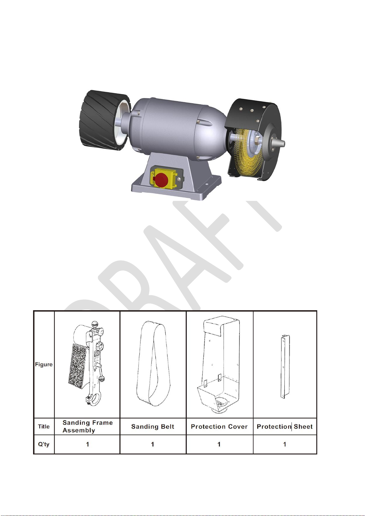
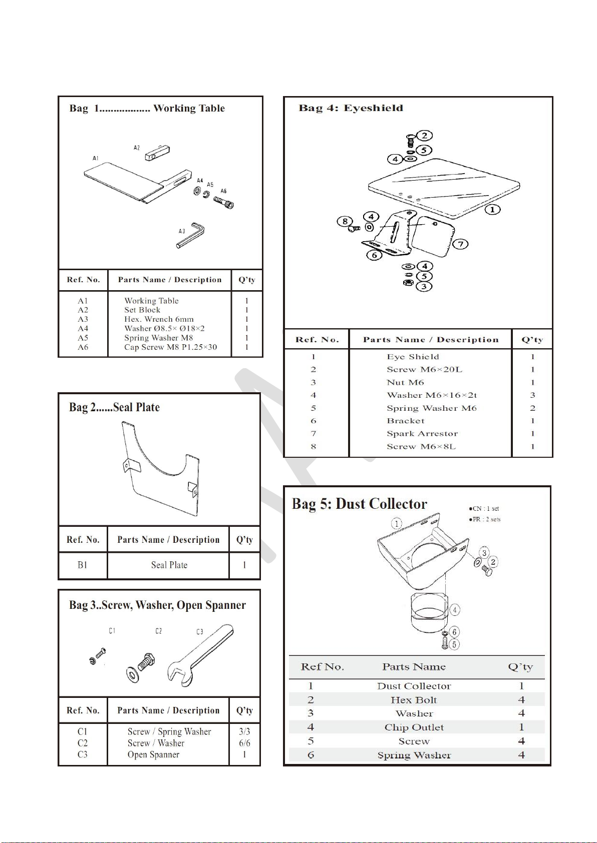
5. UNPACKING AND CHECKING LIST
6. 323BF-BP Exploded View
7. 323BF-BP Part List
1. Declaration of conformity
On our own responsibility we hereby declare that
this product complies with the regulations* listed
on page2.
Designed in consideration with the standards**.
2. Warranty
Tool France guarantees that the supplied
product is free from material defects and
manufacturing faults.
This warranty does not cover any defects which
are caused, either directly or indirectly, by
incorrect use, carelessness, accidental damage,
repair, inadequate maintenance or cleaning and
normal wear and tear.
Any warranty details (i.e. warranty period) can
be found in the General Terms and Conditions
(GTC) that are integral part of the contract.
These GTC can be viewed at the website of your
dealer or sent to you upon request.
Tool France reserves the right to make changes
to the product and accessories at any time.
3. Safety
3.1 Authorized use
This sander is designed for sander metal and a
similar sander only. Machining of other materials
is not permitted and may be carried out in
specific cases only after consulting with the
manufacturer.
The proper use also includes compliance with
the operating and maintenance instructions
given in this manual.
The machine must be operated only by person’s
familiar with its operation and maintenance and
who are familiar with its hazards.
The required minimum age must be observed.
The machine must only be used in a technically
perfect condition.
When working on the machine, all safety
mechanisms and covers must be mounted.
In addition to the safety requirements contained
in these operating instructions and your
country’s applicable regulations, you should
observe the generally recognized technical rules
concerning the operation of metalworking
machines.
Any other use exceeds authorization.
In the event of unauthorized use of the machine,
the manufacturer renounces all liability and the
responsibility is transferred exclusively to the
operator.
3.2 General safety notes
Metalworking machines can be dangerous if not
used properly. Therefore, the appropriate
general technical rules as well as the following
notes must be observed.

6
Read and understand the entire instruction
manual before attempting assembly or operation.
Keep this operating instruction close by the
machine, protected from dirt and humidity, and
pass it over to the new owner if you part with the
tool.
No changes to the machine may be made.
Daily inspect the function and existence of the
safety appliances before you start the machine.
Do not attempt operation in this case, protect the
machine by unplugging the power cord.
Before operating the machine, remove tie, rings,
watches, other jewelry, and roll up sleeves
above the elbows.
Remove all loose clothing and confine long hair.
Wear safety shoes; never wear leisure shoes or
sandals.
Always wear the approved working outfit:
- safety goggles
- ear protection
- dust protection
Do not wear gloves while operating this machine.
Install the machine so that there is sufficient
space for safe operation and work-piece
handling.
Keep work area well lighted.
The machine is designed to operate in closed
rooms and must be bolted stable on firm and
levelled table surface
Make sure that the power cord does not impede
work and cause people to trip.
Keep the floor around the machine clean and
free of scrap material, oil and grease.
Stay alert!
Give your work undivided attention.
Use common sense. Do not operate the
machine when you are tired.
Keep an ergonomic body position. Maintain a
balanced stance at all times.
Do not operate the machine under the influence
of drugs, alcohol or any medication. Be aware
that medication can change your behavior.
Never reach into the machine while it is
operating or running down.
Keep children and visitors a safe distance from
the work area.
Never leave a running machine unattended.
Before you leave the workplace switch off the
machine.
Do not operate the electric tool near inflammable
liquids or gases.
Observe the fire fighting and fire alert options, for
example the fire extinguisher operation and
place.
Do not use the machine in a dump environment
and do not expose it to rain.
Always use a suitable dust collection device
Machine only stock which rests securely on the
table.
Specifications regarding the maximum or
minimum size of the work-piece must be
observed.
Do not stand on the machine.

7
Connection and repair work on the electrical
installation may be carried out by a qualified
electrician only.
Have a damaged or worn power cord replaced
immediately.
Make all machine adjustments or maintenance
with the machine unplugged from the power
source.
3.3 Remaining hazards
When using the machine according to
regulations some remaining hazards may still
exist.
Thrown work-pieces and work-piece parts can
lead to injury.
Dust and noise can be health hazards. Be sure
to wear personal protection gear such as safety
goggles and dust mask. Use a suitable dust
collection system.
The use of incorrect mains supply or a
damaged power cord can lead to injuries
caused by electricity.

8
Technical Data
MODEL
323BF-BP
MOTOR (OUTPUT)
PHASE
WIRE WHEEL / polishing wheel
WIRE SPEED
SANDING BELT
BELT SPEED
DRIVING WHEEL
FLAT GRINDING SUREACE
DIMENSIONS (L x W x H)
MACHINE HEIGHT (W/STAND)
WEIGHT (NET / GROSS)
CABINET STAND (L x W x H)
1.0Kw
Three
200 x 19 x 16mm / 175x20x12
2850rpm
100 x 1100mm
24m/sec
160 x 105mm
105 x 250mm
295 x 285 x 690mm
1480mm
36/37.5kgs
380 x 395 x 810mm
GETTING TO KNOW YOUR MACHINE
Ball Knob
Sanding Frame
Sanding Belt
Working Area
1.Working Table
Stand
Switch
4.Tension Locking Knob
3.Traking Knob
2.Belt Tension Knob Eye
Eye Shield
Safety Cover
Working Area
1. Tension Locking Knob
Turn counter-clockwise about 180∘
before adjusting tension of sanding
belt or changing sanding belt. After
that lock tightly by turning
clockwise.
400V / 50Hz
Noise Level: About 82 dB(A)
1. Work Table
Adjustable between 45∘and 90∘keep
1mm-1.6mm distance from sanding belt.
2. Belt Tension Knob
Turn clockwise about 120∘to make
aluminum roller (part No. 61) downward
9mm to loosen belt for replacement and
turn 120∘back to tie belt up.
3. Tracking Knob
Clockwise turning makes sanding belt
toward right side, and counter-clockwise
turning makes belt toward left side.
Suggest hand adjustment before power
is on.

9
UNPACKING AND CHECKING LIST
LOOSE PARTS IN RECTANGLE BOX
GRINGER
ASSEMBLY Q’TY: 1

10
LOOSE PARTS IN RECTANGLE BOX

11
LOOSE PARTS IN RECTANGLE BOX
Ref No.
Part Name
Q’ty
1
Adaptor
1
2
Disc Washer
1
3
Buffer
1
4
Disc Washer
1
5
Hex Washer
1
6
Rotor Shaft Cap
1
7
Polisher Cover
1
1
2
3
4
5
6
7

12
ASSEMBLY CHART –SANDING BELT
4
3
2
1
1. Remove the left side hex. nut and rubber roller
from shaft.
2. Place frame assembly in. tighten cap screw by
6mm hex.
wrench(Supplied)
3. Mount the rubber roller into frame assembly.
tighten hex.
nut firmly by wrench
1. Observe aluminum roller whether it's tail end is
at the right angle (90°) to the frame.
(T urn tracking knob clockwise may make the
tail end of roller upward).
2. Turn tension locking knob counter-clockwise
about 180°then turn belt tension knob
clockwise about 120°to make aluminum roller
downward and locate sanding belt on the
center of two rollers.
3. Turn belt tension knob counter-clockwise 120°
back to tie belt up.
1. Fix protection sheet by 3 screws.
2. Fix protection cover by 4 screws.
3. Fix seal plate by 2 screws.
BELT BALANCE
1. Turn tracking knob clockwise to make sanding belt
toward right side or turn counter-clockwise to make
belt toward left side. Note: It is only allowed a tiny
adjustment at each turn.
2. Rotate belt by hand. meanwhile adjust tracking
knob.
3. Control the switch for a short on/off starting with
left hand. meanwhile put right hand on tracking
knob for clockwise or counter turning till the belt
runs stably between the two rollers.
Tension
locking
Knob
Belt Tension
Knob

13
ASSEMBLY CHART -SANDING BELT DEVICE
7
This working table is adjustable for the angles
from 45°~90°The 4 angle holes give different
angles of 45°,60°75°,90°by the insertion of the
pin of working table.
6
Use 6mm hex. wrench to fix working table
and its accessories into hole at the desired angles.
5
BELT TENSION ADJUSTMENT
1. Be sure the switch is on OFF position.
2. Test belt tension from the back by thumb press.
3. If the tension is not high enough for working. may
begin the following procedures:
3.1. Loosen hex. nut and turn tension locking knob
counter-clockwise about 180°.
3.2. Turn the belt tension knob clockwise about 120°.
3.3. Open the cover where the position is located down
the tracking knob.
3.4. Clockwise loosen the hex. nut (Part No. 58) by a
supplied 12mm open spanner.
3.5. Turn adjusting rod (Part No. 59) clockwise to increase
belt tension.
NOTE: 1) Each clockwise turning of adjusting rod
makes aluminum roller upward 2.5mm, and
each counter turning shall make the roller
downward 2.5mm.
2) Normally, it is unnecessary to make a
whole turning of 2.5mm, micro adjustment is
always recommended. Each edge turning of
the hex. adjusting rod makes aluminum roller
upward or downward 0.42mm.
3.6. Counter-clockwise tighten the hex. nut (Part No. 58)
to fix the position of adjusting rod.
3.7. Close the cover.
4. Turn belt tension knob counter-clockwise 120°back to
tie belt up.
5. Repeat the procedures of belt balance of the fig. 4
(page 11).
6. After adjusting belt tension. before operating, turn
tension locking knob clockwise to make the shaft (part
no. 67) tightly. And tighten hex. nut to avoid losing.

14
ASSEMBLY CHART -SANDING BELT DEVICE
10
Step
1. Loosen the screw (1), remove (2) Rotor Shaft Cap, and tighten the screw (1).
2. Remove the (3) screw, put on the (4) Safety Cover, and tighten the (3) screw.
3. Assemble (5) Adaptor, (6) Disc Washer, (7) Buffer, (8) Hex Nut, (9) Adaptor Cap in sequence and fix it to
the shaft.
9
Curve Sanding
1. Put frame assembly to horizontal position.
2. Loosen screw A and B showed in figure.
3. open roller covers to proper position and fix it.
4. This machine is now ready for the
operation of curve sanding.
8
1. This machine is designed to allow the sanding
belt to be operated vertically or horizontally
at your comfortable choice.
2. Use 6mm hex. wrench may loosen and
tighten cap screw to adjust frame assembly in
proper angles.
3
1
2
4
5
6
7
8
9

7
1. Loosen hex. nut and turn tension locking
knob counter-clockwise about 180°
2. Turn belt tension knob clockwise about
120°
3. Remove seal plate. protection cover and
the used belt.
4. Locate the new belt on the center of two
rollers.
5. Turn belt tension knob counter clockwise
120°back to tie belt up. Rotate belt by
hand. meanwhile adjust tracking knob as a
pretest before power test.
6. Locate protection cover and seal plate
then use left hand to control the switch
with a short on/off starting. meanwhile put
right hand on tracking knob for clockwise
or counter turning till the belt runs stably
between the two rollers.
7. Check belt tension if the tension is
improper for working then begin the
adjustment procedures until the
tension is satisfactory.
8. Repeat the procedures of hand test &
power test for belt balance as the fig 4
(page 11).
9. After adjusting belt tension, before
operating, turn tension locking knob
clockwise to make the shaft (part
no.67) tightly. And tighten hex. nut to
avoid losing.
10. Adjust frame assembly and fix working
table at the desired angles.
REPLACEMENT OF WHEEL
1. Remove tool rest and eye shield or dust collector unit from wheel cover by taking off bolts and
screws.
2. Take off screws to allow removing wheel cover as figure.
3. Remove nut, disc washer or balancing flange and waste wheel.
4. Put new wheel and every parts back in reverse order. It's important to make a good adjustment of
balancing before assembling wheel covers. This message could be learned
5. For your safety, check all screws and bolts. Make sure they are all well fixed before switch
on.
REPLACEMENT OF BELT

8
323BF-BP Exploded View

9
323BF-BP Parts List
Index Part
No. No. Description Size Qty.
1 ................ PM-323001 ..................... Eye Shield Set ..................................... ............................................................. 1
2 ................ PM-323002 ..................... Int. Cover ............................................. ............................................................. 1
3 ................ PM-323003 ..................... Disc Washer ........................................ ............................................................. 2
3-2 ............. PM-323003 ..................... Balancer Set ........................................ ............................................................. 1
4 ................ PM-323004 ..................... Wire Brush ........................................... ............................................................. 1
5 ................ TS-0561071 .................... Hex. Nut .............................................. 5/8" ....................................................... 1
6 ................ TS-2172012 .................... Machine Screw .................................... M5 x 8L ................................................ 9
7 ................ PM-323007 ..................... Wheel Cover ........................................ ............................................................. 1
8 ................ PM-323008 ..................... Hex. BOLT ........................................... ............................................................. 4
9 ................ TS-1550041 .................... Washer ................................................ M6 x 18 x 2.0T ..................................... 4
9-3 ............. TS-2361051 .................... Spring Washer ..................................... M5 x12 x1T .......................................... 2
10 .............. PM-323010 ..................... Dust Collector ...................................... ............................................................. 1
11 .............. TS-081F031 .................... Machine Screw .................................... 1/4" x 1/2" ............................................. 3
12 .............. TS-2361061 .................... Spring Washer ..................................... M6 ...................................................... 19
13 .............. TS-1533042 .................... Machine Screw .................................... M6 x 12L .............................................. 8
14 .............. PM-323014 ..................... Washer ................................................ M6 x 18 x 2.0T ..................................... 8
15 .............. TS-2172002 .................... Cap Screw ........................................... 3/16"x1/4" ............................................. 4
15-1 ........... TS-2172062 .................... Cap Screw ........................................... 3/16"x1" ................................................ 4
16 .............. TS-2361051 .................... Spring Washer ..................................... M5 ........................................................ 9
17 .............. PM-323017 ..................... Right Support ...................................... ............................................................. 1
18 .............. PM-323018 ..................... Ball Bearing ......................................... ............................................................. 1
20 .............. PM-323020 ..................... Shaft .................................................... ............................................................. 1
20-1 ........... PM-323020-1 .................. Fan ...................................................... ............................................................. 1
21 .............. PM-323021 ..................... Wiring Housing .................................... ............................................................. 1
22 .............. PM-323022 ..................... Wiring .................................................. ............................................................. 1
25 .............. PM-323025 ..................... Ball Bearing ......................................... ............................................................. 1
26 .............. PM-323026 ..................... Left Support ......................................... ............................................................. 1
34 .............. TS-2172032 .................... Machine Screw .................................... 3/16" x 1/2" ........................................... 4
35 .............. PM-323035 ..................... Screw .................................................. ............................................................. 1
38 .............. TS-2172022 .................... Machine Screw .................................... 3/16" x 3/8" ........................................... 3
39 .............. PM-323039 ..................... Int. Washer .......................................... M4.5 ..................................................... 1
40 .............. PM-323040 ..................... Copper Set .......................................... ............................................................. 1
41 .............. TS-2361051 .................... Washer ................................................ M5 ........................................................ 1
42 .............. PM-323042 ..................... Base .................................................... ............................................................. 1
43 .............. PM-323043 ..................... Fixing Plate .......................................... ............................................................. 1
44 .............. PM-323044 ..................... Strain Relief ......................................... ............................................................. 1
45 .............. PM-323045 ..................... Power Cord ......................................... ............................................................. 1
46 .............. TS-2285303 .................... Screw .................................................. 3/16" x 1-1/4"........................................ 2
46-1 ........... TS-2361051 .................... Hex. Nut .............................................. 3/16" ..................................................... 1
47 .............. PM-323047 ..................... NVR ..................................................... ............................................................. 1
48 .............. PM-323048 ..................... Pad ...................................................... ............................................................. 4
49 .............. PM-323049 ..................... Base Plate ........................................... ............................................................. 1
50 .............. PM-323050 ..................... Tracking Knob ..................................... ............................................................. 1
51 .............. PM-323051 ..................... Spring .................................................. ............................................................. 1
52 .............. PM-323052 ..................... Washer ................................................ ............................................................. 1
53 .............. PM-323053 ..................... Sliding Block ....................................... ............................................................. 1
54 .............. PM-323054 ..................... Pin ....................................................... ............................................................. 1
55 .............. PM-323055 ..................... Spring .................................................. ............................................................. 1
56 .............. PM-323056 ..................... Shaft .................................................... ............................................................. 1
57 .............. PM-323057 ..................... Snap Ring ............................................ ............................................................. 1
58 .............. PM-323058 ..................... Ball Bearing ......................................... ............................................................. 2
59 .............. PM-323059 ..................... Bush .................................................... ............................................................. 1
60 .............. PM-323060 ..................... Snap Ring ............................................ ............................................................. 1
61 .............. PM-323061 ..................... Aluminum Roller .................................. ............................................................. 1
62 .............. TS-1540061 .................... Hex. Nut .............................................. M8 ........................................................ 1
63 .............. PM-323063 ..................... Adjusting Rod ...................................... ............................................................. 1
64 .............. PM-323064 ..................... Press Block ......................................... ............................................................. 1
65 .............. PM-323065 ..................... Hex. Nut-Loose proof .......................... ............................................................. 1

10
Index No Part No Description Size Qty
66 .............. TS-2361081 .................... Spring Washer ..................................... M8 ........................................................ 2
67 .............. PM-323067 ..................... Cam ..................................................... ............................................................. 1
68 .............. PM-323068 ..................... Cam Shaft ........................................... ............................................................. 1
69 .............. PM-323069 ..................... Screw Shaft ......................................... ............................................................. 1
70 .............. PM-323070 ..................... Ball Knob ............................................. ............................................................. 2
71 .............. PM-323071 ..................... Loosen-Tight Plate .............................. ............................................................. 1
72 .............. TS-1482031 .................... Cover Screw ........................................ M6 x 15L .............................................. 1
73 .............. PM-323073 ..................... Wave Washer ...................................... ............................................................. 1
74 .............. PM-323074 ..................... Cover ................................................... ............................................................. 1
75 .............. PM-323075 ..................... Cover plate .......................................... ............................................................. 1
76 .............. PM-323076 ..................... Adjusting Plate .................................... ............................................................. 1
77 .............. PM-323077 ..................... Screw Shaft A ...................................... ............................................................. 1
80 .............. PM-323079 ..................... Protection Sheet 1 ............................... ............................................................. 1
81 .............. PM-323080 ..................... Protection Sheet 2 ............................... ............................................................. 1
82 .............. PM-323081 ..................... Belt Support ......................................... ............................................................. 1
83 .............. PM-323082 ..................... Hex. Shaft ............................................ ............................................................. 1
84 .............. PM-323083 ..................... Sanding Frame .................................... ............................................................. 1
85 .............. TS-1504071 .................... Cap Screw ........................................... M8 x 35L .............................................. 3
86 .............. PM-323085 ..................... Rubber Roller ...................................... ............................................................. 1
87 .............. PM-323086 ..................... Sanding Belt ........................................ ............................................................. 1
88 .............. PM-323087 ..................... Hex. Nut-Left Thread ........................... 7/8" ....................................................... 1
89 .............. TS-1504061 .................... Cap Screw ........................................... M8 x 30L .............................................. 1
90 .............. PM-323089 ..................... Set Block ............................................. ............................................................. 1
91 .............. PM-323090 ..................... Working Table ..................................... ............................................................. 1
92 .............. PM-323091 ..................... Sanding Belt Protector 1 ..................... ............................................................. 1
93 .............. PM-323092 ..................... Sanding Belt Protector 2 ..................... ............................................................. 1
94 .............. TS-0050051 .................... Hex bolt ............................................... 1/4" x 1" ................................................ 4
95 .............. TS-1482021 .................... Hex bolt ............................................... M6 x 12L .............................................. 8
96 .............. PM-323095 ..................... Chip Outlet .......................................... ............................................................. 1
97 .............. PM-323096 ..................... Seal Plate ............................................ ............................................................. 1
98 .............. PM-323097 ..................... Graphite Packing ................................ ............................................................. 1
100 ............ 9190* ............................... Adapt (Including #100~#103) .............. 26xM12x135mm .................................. 1
104 ............ 9493* ............................... Adapt Cap ........................................... Ø25 x 36.5 .......................................... 1
105 ............ 9339* ............................... Mop/Buffer ........................................... 7"x12mm .............................................. 1
106 ............ PM-322116 ..................... Rotor Shaft Cap ................................... ............................................................. 1
107 ............ PM-322107 ..................... Screw .................................................. M4x6L .................................................. 3
108 ............ PM-322118 ..................... Safety Cover ........................................ 8" .......................................................... 1
110 ............ PM-323110 ..................... Open Spanner ..................................... ............................................................. 1
111 ............ PM-323111 ..................... Hex. Wrench ........................................ ............................................................. 1
112 ............ PM-323112 ..................... Socket Wrench .................................... ............................................................. 1

ABOUT WORKSTAND [Optional]
Unpacking and checking list
*Universal Workstand *Cabinet Workstand
Stand Leg (front & rear)
Stand Leg (left & right)
Stand Top
Square Neck Bolt (5/16"-18NCx5/8")
Hex. Bolt(5/16"-18NCx1.5")
Hex. Bolt(5/16")
Spring Washer (M8)
Washer (M8x18x2t)
1
2
3
4
5
6
7
8
2
2
1
4
2
6
6
8
Ref. No. Parts Name / Deseription Q’ty
Stand
Bottom Plate
Hex Bolt(M8X20L)
Spring Washer(M8)
Washer(M8x30x3t)
Washer(M8x18x2t)
Hex Bo1t(M8x35L)
Cooler Boxer
Screw(M6x16)
Washer(M6x16x2t)
Hex Bolt(M6x12)
Spring Washer(M6)
1
2
3
4
5
6
7
8
9
10
11
12
1
1
4
6
4
2
2
1
2
6
4
4
Ref. No. Parts Name / Deseription Q’ty

Dust Collection Tank
Dust Collection Bag
Tank Cover, Collector Body with Motor
Chip Inlet (5"-4")
Chip Inlet (4"-1.5")
Hose (4")
Clamp (4.5")
Screw (M5x8)
Screw (M6x16)
Washer (M6x25x2t)
Screw (M6x12)
Washer (M6x18x2t)
1
2
3
4
5
6
7
8
9
10
11
12
1
1
4
6
4
2
2
1
2
6
4
4
Ref. No. Parts Name / Deseription Q’ty
Unpacking and Checking List
[Optional]
DUST COLLECTION DEVICE
Table of contents
Other Promac Sander manuals
Popular Sander manuals by other brands

AEG Powertools
AEG Powertools BEX 18-125 Original instructions

Scheppach
Scheppach DS920 Translation of original instruction manual

Bosch
Bosch 1278VSK Operating/safety instructions

American Sanders
American Sanders 3DS Operator's manual

Craftsman
Craftsman 315.116302 owner's manual

WORKERS BEST
WORKERS BEST WB 250 KSM manual