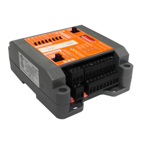
promesstec UREG 200 User manual

Version 2.1.1
promesstec GmbH I Niedersachsenstraße 4 I D- 48465 Schüttorf I Tel.:+49 (0)5923/ 90 229 0 I Fax:+49 (0)5923/ 90 229 29
E-Mail: office@promesstec.com I Internet: www.promesstec.com
User manual
Universal controller
UREG 200

2
promesstec GmbH I Niedersachsenstraße 4 I D- 48465 Schüttorf I Tel.:+49 (0)5923/ 90 229 0 I Fax:+49 (0)5923/ 90 229 29
E-Mail: office@promesstec.com I Internet: www.promesstec.com
Content
1. General................................................................................................................ 5
1.1 For Information.............................................................................................. 5
1.2 Signs and abbreviations................................................................................ 5
2. transport, packaging and storage........................................................................ 6
2.1 transport........................................................................................................ 6
2.2 packaging...................................................................................................... 6
2.3 storage .......................................................................................................... 6
3. safety instructions................................................................................................ 7
3.1 Intended use of the product........................................................................... 7
3.2 Personnel qualification .................................................................................. 7
3.3 Special hazards............................................................................................. 8
4. Commissioning and operation............................................................................. 9
4.1 Equipment ..................................................................................................... 9
4.2 Order code .................................................................................................. 11
4.3 Programming interface & DIP switches....................................................... 12
4.4 Buttons and display..................................................................................... 13
4.5 Menu overview ............................................................................................ 16
4.6 System Modes............................................................................................. 17
4.7 Parameter description ................................................................................. 18
5. Installation......................................................................................................... 24
5.1 Before mounting.......................................................................................... 24
5.2 Installation ................................................................................................... 25
5.3 Connection preparation............................................................................... 26
5.4 Power supply............................................................................................... 27
5.5 Sensor connection in general...................................................................... 27
5.6 Connecting thermocouples.......................................................................... 28
5.7 RTD connect ............................................................................................... 29
5.8 Linear voltage input..................................................................................... 29
5.9 CT/Current transformer connection............................................................. 32
5.10 Event input............................................................................................... 33
5.11 Control output OUT1................................................................................ 34
5.12 Control output OUT2................................................................................ 36
5.13 Alarm outputs........................................................................................... 38
5.14 RS-485 interface ...................................................................................... 39

3
promesstec GmbH I Niedersachsenstraße 4 I D- 48465 Schüttorf I Tel.:+49 (0)5923/ 90 229 0 I Fax:+49 (0)5923/ 90 229 29
E-Mail: office@promesstec.com I Internet: www.promesstec.com
5.15 RS-232 interface ...................................................................................... 40
5.16 Analogue retransmission.......................................................................... 41
5.17 Programming interface............................................................................. 41
6. Programming the basic functions ..................................................................... 42
6.1 input 1 (IN1)................................................................................................. 43
6.2 output 1 and 2 (OUT1 / OUT2).................................................................... 44
6.3 Setting the User Menu (SEL1 –SEL5)........................................................ 45
6.4 Heating only control..................................................................................... 45
6.5 Cooling only control..................................................................................... 47
6.6 Heating-cooling control................................................................................ 48
6.7 Holding time ................................................................................................ 50
6.8 Process alarms............................................................................................ 51
6.9 Differenzalarm............................................................................................. 53
6.10 Differential band alarm............................................................................. 55
6.11 Control loop interruption alarm................................................................. 56
6.12 Sensor break alarm.................................................................................. 57
6.13 SP1 Setting range.................................................................................... 57
6.14 PV1 Offset................................................................................................ 58
6.15 Error behaviour / display .......................................................................... 59
6.16 Bumpless Transfer BPLS......................................................................... 60
6.17 Self-optimization....................................................................................... 61
6.18 Automatic setting...................................................................................... 62
6.19 Manual setting.......................................................................................... 65
6.20 DC Sensor supply .................................................................................... 68
6.21 Manual operation ..................................................................................... 69
6.22 Display Mode ........................................................................................... 69
6.23 Restoring factory settings......................................................................... 71
7. Programming the full range of functions (FULL)................................................ 72
7.1 Event input (EIFN)....................................................................................... 72
7.2 Second set point.......................................................................................... 73
7.3 Second PID setting...................................................................................... 73
7.4 Ramps & Timers.......................................................................................... 74
7.5 External set point......................................................................................... 76
7.6 Difference regulations.................................................................................. 77
7.7 Control limitation.......................................................................................... 77
7.8 Data transmission RS interfaces ................................................................. 78

4
promesstec GmbH I Niedersachsenstraße 4 I D- 48465 Schüttorf I Tel.:+49 (0)5923/ 90 229 0 I Fax:+49 (0)5923/ 90 229 29
E-Mail: office@promesstec.com I Internet: www.promesstec.com
7.9 Analog retransmission................................................................................. 80
7.10 Digital filter ............................................................................................... 81
7.11 Sleep mode.............................................................................................. 81
7.12 Pump control............................................................................................ 82
7.13 Parameter lock with event input............................................................... 84
8. Calibration......................................................................................................... 84
9. Demounting, Return, Cleaning and Disposal..................................................... 85
9.1 Demounting................................................................................................. 85
9.2 Return.......................................................................................................... 85
9.3 Cleaning...................................................................................................... 85
9.4 Disposal....................................................................................................... 85
10. Warranty & Return.......................................................................................... 86
11. Technical specifications.................................................................................. 87
12. Your parameters notes ................................................................................... 89

5
promesstec GmbH I Niedersachsenstraße 4 I D- 48465 Schüttorf I Tel.:+49 (0)5923/ 90 229 0 I Fax:+49 (0)5923/ 90 229 29
E-Mail: office@promesstec.com I Internet: www.promesstec.com
1. General
1.1 For Information
-These operating manual provides important information on handling the
measuring element. A prerequisite for safe working is compliance with all
specified safety notes and instuctions for action.
-The qualified personnel must have read and understood these operating manual
before mounting and starting up the sensor.
-These operating manual is a component part of the product. Therefore, keep
them in a place that is accessible to all users at all times, close to the place of
use.
-The local regulations and safety rules applicable to the area of application of the
sensor must be observed.
-If the serial number on the type label is no longer readable (e.g. due to
mechanical damage), traceability is no longer ensure.
-The sensor described in the user manual are developed and manufactured
according to the newest finding. All components are subject strict quality and
environmental criteria during production.
-The manufacturer shall not be liable if damage is caused by improper use,
non-observance of these operating instructions, use of insufficiently qualified
personnel and unauthorized modifications to the sensor.
1.2 Signs and abbreviations
Warning!
Non-observance can lead to injuries to persons and / or destuction of
the device. There may be danger to life.
Attention!
Non-observance can lead to incorrect operation of the device or
damage to property.
Information!
Non-observance can influence the operation of the device or cause
undesired device reactions.
Danger!
If the safety instructions are not observed, there is a risk of serious or
fatal injury from electric current.
UREG 200

6
promesstec GmbH I Niedersachsenstraße 4 I D- 48465 Schüttorf I Tel.:+49 (0)5923/ 90 229 0 I Fax:+49 (0)5923/ 90 229 29
E-Mail: office@promesstec.com I Internet: www.promesstec.com
Warning!
A dangerous situation may possibly occur, which can lead to burns
due to hot surfaces or liquids if they are not avoided.
2. transport, packaging and storage
2.1 transport
Inspect the device for a damage that may have occurred during transport. Report
obvious damage immediately.
2.2 packaging
Do not remove the packaging until immediadtely before assembly. Keep the
packaging, because it provides optimal protection during transport (e.g. chageable
installation location, return).
2.3 storage
Avoid the following influences during longer storage:
-Direct sinlight or close to hot ojects
-Mechanical vibration, mechanical shock (hard set up)
-Soot, steam, dust and corrosive gases
If possible, store the device in the original packaging or appropriate packaging.

7
promesstec GmbH I Niedersachsenstraße 4 I D- 48465 Schüttorf I Tel.:+49 (0)5923/ 90 229 0 I Fax:+49 (0)5923/ 90 229 29
E-Mail: office@promesstec.com I Internet: www.promesstec.com
3. safety instructions
Further important safety instructions can be found in the individual
chapters.
3.1 Intended use of the product
The sensor is desiged and constructed exclusively for the intended use described
here and may only be used as follows. The technical specifications in these
operating instructions must be observed.
Improper handling or operation of the device unit outside the technical specifications
requires immediate decommissioning and inspection by the manufacturer. If the unit
is transported from a cold to a warm environment, condensation may cause the unit
to malfunction. Wait for the temperature of the appliance to adjust to the room
temperature before starting it up again. Claims of any kind are excluded due to
improper use.
3.2 Personnel qualification
Risk of injury due to inadequate qualification. Improper handling can
lead to considerable personal injury and damage to property.
The activities described in these operating instructions may only be
carried out by qualified personnel with the following qualifications.
Keep unqualified personnel away from the hazardous areas.
For installation and commissioning of the sensor, these persons must be familiar
with the applicable country-specific directives and standards and have the
appropriate qualificationions. They must have knowledge of measurement and
control technology be familiar with electrical circuits and be able to carry out the
work described and recognise possible dangers independently. Depending on the
conditions of use, other knowledge may also be required, e.g. about aggressive
media.

8
promesstec GmbH I Niedersachsenstraße 4 I D- 48465 Schüttorf I Tel.:+49 (0)5923/ 90 229 0 I Fax:+49 (0)5923/ 90 229 29
E-Mail: office@promesstec.com I Internet: www.promesstec.com
3.3 Special hazards
Observe the country- specific regulations (e.g. standards) and, in
the case of special applications, observe the applicable standards
and directives (e.g. for hazardous media such as Acetylene,
flammable or toxic substances as well as refrigeration plants and
compressors).
If the relevant regulations are not observed, serious personal
injury and damage to property may result!
Electrostatic discharge (ESD) protection is required. Proper use of
grounded work surfaces and personal wrist straps is required when
working with open circuit (printed circuit boards) to prevent damage
to sensitive electronic components from electrostatic discharge.
There is danger to life from electric current. There is a immediate risk
of death if live parts are touched. Installation and mounting of
electrical equipment may only be carried out by qualified electricans.
When operating with a defective power supply unit (e.g. short-circuit
from mains voltage to output voltage), life-threatening voltages can
result at the device.
Residual media in device that have been removed can be hazardous
to persons, that environment and equipment. Sufficiet precations
must be taken. This device must not be used in safety or emergency
stop devices. Incorrect applications of the device can lead to inuries.
In case of a fault, aggressive media at extreme temperatures and
under high pressure or vacuum may be present at the device.

9
promesstec GmbH I Niedersachsenstraße 4 I D- 48465 Schüttorf I Tel.:+49 (0)5923/ 90 229 0 I Fax:+49 (0)5923/ 90 229 29
E-Mail: office@promesstec.com I Internet: www.promesstec.com
4. Commissioning and operation
4.1 Equipment
High-resolution 18-Bit AD Input converter
High-resolution 15-Bit DA Output converter
High input scanning (5Hz)
Two menu levels
Parameterisation in the user menu
Pump control
Fuzzy + PID microprocessor-based control
Differential control
Automatic setting
Self-optimisation
Sleep mode function
"Soft-start" via ramp and ramp-up time
Programmable input (TC, RTD, mA, VDC)
Analogue input for remote setpoint and CT
Event input for switching function and setpoint
Programmable digital filter
Hardware Menu Lock + Remote Menu Lock
Alarm in case of control loop interruption
Alarm in case of heating failure
Sensor break alarm + Bumpless transfer
RS-485, RS-232 interface
Analogue retransmission
DC Power supply for head transmitter
Safety UL / CSA / IEC1010-1
EMC / CE EN61326
The UREG200 is a fuzzy logic + PID microprocessor-based controller with a bright,
4-digit LED display for process value display. The fuzzy logic technique enables the
process to reach the setpoint as quickly as possible, without overdriving and distur-
bing the external load. The controllers have a 1/8 DIN housing with the dimensions
48mm x 96mm and a mounting depth of 70mm. All parameters and input configura-
tions can be set via the three operating keys. With the user-defined quick access
menu it is possible to set the five most common parameters individually in front of
the normal setup menu (Parameters SEL1 to SEL5).
The operating voltage of the UREG200 is 90 –264 VAC or 11-26 VAC/VDC. De-
pending on the equipment, the controller has two 2A relay control outputs and two
2A alarm relays, alternatively analogue output 0/4-20mA or SSR relay driver. The
1st analogue input is freely programmable for PT100, thermocouples type J, K, T,
E, B, R, S, N, L, Current input 0/4-20mA or voltage input 0-1VDC, 0-5VDC, 1-5VDC
or 0-10VDC. The 2nd input can be set to current input 0/4-20mA or Voltage input 0-
1VDC, 0-5VDC, 1-5VDC or 0-10VDC. The inputs are digitised with an 18-bit A-D
converter for further processing. The high sampling rate of 5Hz enables the use in

10
promesstec GmbH I Niedersachsenstraße 4 I D- 48465 Schüttorf I Tel.:+49 (0)5923/ 90 229 0 I Fax:+49 (0)5923/ 90 229 29
E-Mail: office@promesstec.com I Internet: www.promesstec.com
dynamic processes such as pressure and flow control. The integrated self-optimisa-
tion adjusts the control parameters and ensures rapid optimisation of the control
process.
Options available for the UREG200 include RS-232, RS-485 and an additional 0/4-
20mA analogue output for retransmission. These interfaces enable communication
with a process control system or for displaying the values on a separate display, as
well as for data logging on an external device.
The controller can be programmed 1. manually using the front keys, or 2. using the
UREG-Konfig software with the PC and transmitted via RS232 or RS485 interface.
What is Fuzzy Control?
The PID control principle is based on a mathematical calculation between setpoint
and actual value. Conventional PID controllers react to the changes of the process
value with the delay of the calculation depending on the dynamics of the actual
value.
The fuzzy controller enables the process to be controlled dynamically; by observing
the actual values depending on the control, the fuzzy controller learns to act faster
and more efficiently in similar constellations. The fuzzy logic is a linguistic controller
and not numerical like the PID controller. Through the "experiences" of the fuzzy
control, the control behaviour of the PID is constantly optimised.
PID+FUZZY Block diagram

11
promesstec GmbH I Niedersachsenstraße 4 I D- 48465 Schüttorf I Tel.:+49 (0)5923/ 90 229 0 I Fax:+49 (0)5923/ 90 229 29
E-Mail: office@promesstec.com I Internet: www.promesstec.com
The function of the fuzzy logic is to set the PID parameters internally to achieve a
flexible and adaptive output manipulation MV for different processes. For example:
The temperature difference is large and the change is fast, then ∆MV is large.
The temperature difference is large and the change is slow, then ∆MV is small.
The combination of PID + Fuzzy Control has proven to be an efficient method for
optimising the control behaviour, please refer to the following diagram for a compa-
rison of the control curves.
Comparison curve PID to FUZZY+PID controller
4.2 Order code
See datasheet

12
promesstec GmbH I Niedersachsenstraße 4 I D- 48465 Schüttorf I Tel.:+49 (0)5923/ 90 229 0 I Fax:+49 (0)5923/ 90 229 29
E-Mail: office@promesstec.com I Internet: www.promesstec.com
4.3 Programming interface & DIP switches
Programming port & DIP switch
The programming port can be used for offline programming and diagnostics. Do not
use this port during normal control operation.
When delivered, input 1 is preset for the connection of thermocouples or resistance
thermometers and all menu parameters are enabled.

13
promesstec GmbH I Niedersachsenstraße 4 I D- 48465 Schüttorf I Tel.:+49 (0)5923/ 90 229 0 I Fax:+49 (0)5923/ 90 229 29
E-Mail: office@promesstec.com I Internet: www.promesstec.com
The menu lock can be used to restrict access to the parameters. Even when locked,
all parameters are displayed in the menu.
SEL1- SEL5 show the parameters enabled in quick access.
4.4 Buttons and display
The UREG200 controller is fully programmable via the front keys. The available key
functions can be found in the following table.
Key functions:
Key
Function
describtion
Button HIGH
Pressing once increases the parameter value by one digit.
By holding down the parameter value is quickly increased.
Button DOWN
Pressing once decreases the parameter value by one digit.
By holding down the parameter value is quickly decreased.
Button BLANK
Pressing takes you to the next parameter.
for 3 sec.
Enter button
Allows access to the "USER MENU", in various other
menus this confirms the entry or saves a value.
for 6 sec.
Start recording
Deletes the stored process values PVHI and PVLO and
starts the new recording of the process limit values.
simultaneously
Scroll backwards
Pressing takes you to the previous parameter.
simultaneously
MODE
Press to select the operating mode.
simultaneously
RESET
Press to return to the operating display.
for 3 sec.
SLEEP Mode
The controller goes into SLEEP mode, but this must be
enabled in the menu item SLEP.
simultaneously
Internal setup
This menu item is only available for maintenance work
by promesstec.
Incorrect settings can cause the controller to behave
incorrectly!

14
promesstec GmbH I Niedersachsenstraße 4 I D- 48465 Schüttorf I Tel.:+49 (0)5923/ 90 229 0 I Fax:+49 (0)5923/ 90 229 29
E-Mail: office@promesstec.com I Internet: www.promesstec.com
Display description
Meaning of the display symbols
Display of a 5-digit number!
For numbers with decimal places,
the last digit is not displayed.
-199,99 is displayed as -199,9.
4553,6 is displayed as 4553.
For numbers without decimal
places, the value is displayed
alternately.
-19999 is displayed as:
45536 is displayed as:
-9999 is displayed as:

15
promesstec GmbH I Niedersachsenstraße 4 I D- 48465 Schüttorf I Tel.:+49 (0)5923/ 90 229 0 I Fax:+49 (0)5923/ 90 229 29
E-Mail: office@promesstec.com I Internet: www.promesstec.com
Display when switching on
All segments and LEDs remain
off for 0.5 sec.
All display elements light up for
2 sec.
The current programme version
is displayed for 2.5 sec.
Example: Programme version
3.39
For 2.5 sec. the serial number is
shown on both displays.
Example: Serial number 1.5.22.192
The internal operating hours
counter is displayed for 2.5 sec.
Example: 23456.2 hours

16
promesstec GmbH I Niedersachsenstraße 4 I D- 48465 Schüttorf I Tel.:+49 (0)5923/ 90 229 0 I Fax:+49 (0)5923/ 90 229 29
E-Mail: office@promesstec.com I Internet: www.promesstec.com
4.5 Menu overview

17
promesstec GmbH I Niedersachsenstraße 4 I D- 48465 Schüttorf I Tel.:+49 (0)5923/ 90 229 0 I Fax:+49 (0)5923/ 90 229 29
E-Mail: office@promesstec.com I Internet: www.promesstec.com
4.6 System Modes
The controller works as a closed control loop in nor-
mal operation. If you call up the "User Menu",
"Setup Menu" or "Display Mode" in control mode,
the control loop is not interrupted. This also applies
to the activation of the event input.
Under certain conditions, the controller leaves nor-
mal operation and enters an exception mode. The
exception modes are: Sleep mode, Manual regula-
tion mode, error mode, calibration mode and Auto-
tuning mode. These modes operate in open loop
except for Auto-tuning mode, which operates in
ON-OFF plus PID loop.
The operating modes are staggered in the following
priorities. A low priority mode cannot affect a higher
priority mode, see picture.
Priorities of the operating modes
Calibration mode, auto-tuning mode and normal control mode have the same priority.
The sleep mode has the highest priority.
System Modes
sleep mode
see chapter 4-11
manual regulation mode
see chapter 3-22
error mode
see chapter 3-16
calibration mode
see chapter 6
auto-tuning mode
see chapter 3-19
Normal control mode
see chapter 3-23, 3-25, 4-1

18
promesstec GmbH I Niedersachsenstraße 4 I D- 48465 Schüttorf I Tel.:+49 (0)5923/ 90 229 0 I Fax:+49 (0)5923/ 90 229 29
E-Mail: office@promesstec.com I Internet: www.promesstec.com
4.7 Parameter description
Parameter description
Included in
Base
function
Parameter
Name
Display
Parameter
description Range Default
Value
Yes SP1 Set point 1 Low: SP1L High SP1H
100,0 °C
Yes TIME Timer Low: 0 High: 6553,5 min. 0
Yes A1SP Alarm 1 Switching point See table 1.5, 1.6
100,0 °C
Yes A1DV Alarm 1 Difference
Low: -200,0 °C High: 200,0°C 10,0 °C
Yes A2SP Alarm 2 Switching point See table 1.5, 1.7
100,0 °C
Yes A2DV Alarm 2 Difference
Low: -200,0 °C High: 200,0°C 10,0 °C
No RAMP Ramps rate
Low: 0 High: 500,0 °C 0
Yes OFST
Offset value for
P control Low: 0 High: 100,0 25
No REFC
Reference constant
for special functions
Low: 0 High: 60 2
Yes SHIF PV1 Switch back offset
Low: -200,0 °C High: 200,0°C 0
Yes PB1 Proportional band 1
Low: 0 High: 500,0 °C 10,0 °C
Yes TI1 Integral time 1
Low: 0 High: 1000sec. 100
Yes TD1 Difference time 1
Low: 0 High: 360,0 sec. 25
Yes CPB Cooling proportional band
Low: 1 High: 255% 100
Yes DB
Heating-Cooling Dead
Band / negative value =
overlapping
Low: -36,0 High: 36,0% 0
No SP2 Set point 2 See table 1.5, 1.7
37,8 °C
No PB2 Proportional band 2
Low: 0 High: 500,0 °C 10,0 °C
No TI2 Integral time 2
Low: 0 High: 1000sec. 100
No TD2 Difference time 2
Low: 0 High: 360,0 sec. 25
Yes O1HY Output hysteresis 1
Low: 0,1 High: 55,6 °C 0,1
Yes A1HY Hysterese-Alarm 1
Low: 0,1 High: 10,0 °C 0,1
Yes A2HY Hysterese-Alarm 2
Low: 0,1 High: 10,0 °C 0,1
No PL1 Limitation output 1
Low: 0 High: 100% 100
No PL2 Limitation output 2
Low: 0 High: 100% 100
Yes FUNC Setup menu catch
0 : Basic function
1 : all function 1
No COMM
Communication interfaces
selection
0 : No interface
1 : RS-485 interface
2 : RS-232 interface
3 : 4-20mA Retransfer
4 : 0-20mA Retransfer
5 : 0-1V Retransfer
6 : 0-5V Retransfer
7 : 1-5V Retransfer
8 : 0-10V Retransfer
1
No PORT Transfer protocol
0 : Modbus RTU 0
No ADDR Interface address
Low: 1 High: 255 -
User
Menu
Setup
Menu

19
promesstec GmbH I Niedersachsenstraße 4 I D- 48465 Schüttorf I Tel.:+49 (0)5923/ 90 229 0 I Fax:+49 (0)5923/ 90 229 29
E-Mail: office@promesstec.com I Internet: www.promesstec.com
Included
In
Base
Function
Parameter
Name
Display
Parameter
describtion Range Standard
Value
No BAUD
Transmission speed
0 : 0,3 Kbits/s
1 : 0,6 Kbits/s
2 : 1,2 Kbits/s
3 : 2,4 Kbits/s
4 : 4,8 Kbits/s
5 : 9,6 Kbits/s
6 : 14,4 Kbits/s
7 : 19,2 Kbits/s
8 : 28,8 Kbits/s
9 : 38,4 Kbits/s
5
No DATA Number of bits
0 : 7 Data bit
1 : 8 Data bit 1
No PARI Parity
0 : straight
1 : odd
2 : none
0
No STOP Stop bit
0 : one Stop bit
1 : two Stop bits
No AOFN
Analog output function
0 : Value IN1
1 : Value IN2
2 : Difference IN1 - IN2
3 : Difference IN2 - IN1
4 : Set point SV
5 : OUT1 Manipulation
6 : OUT2 Manipulation
7 : Difference PV-SV
0
No AOLO
Analog output
LOW-scaling Low: -19999 High: 45536 0°C
No AOHI
Analog output
HIGH-scaling Low: -19999 High: 45536 100°C
Yes IN1 IN1 Sensor type
0 : TC type J
1 : TC type K
2 : TC type T
3 : TC type E
4 : TC type B
5 : TC type R
6 : TC type S
7 : TC type N
8 : TC type L
9 : PT100 DIN
10 : PT100 JIS
11 : 4...20mA linear
12 : 0...20mA linear
13 : 0...1VDC linear
14 : 0...5VDC linear
15 : 1...5VDC linear
16 : 0...10VDC linear
17 : Special adjustment
1
Ja IN1U IN1 unit
0 : °C
1 : °F
2 : Process unit
Ja DP1 IN1 Decimal point
0 : without decimal point
1 : 1 decimal point
2 : 2 decimal point
3 : 3 decimal point
1
Ja IN1L IN1 LOW-scaling
Low: -19999 High: 45536 0
Ja IN1H IN1 HIGH-scaling
Low: -19999 High: 45536 1000
Setup
Menu

20
promesstec GmbH I Niedersachsenstraße 4 I D- 48465 Schüttorf I Tel.:+49 (0)5923/ 90 229 0 I Fax:+49 (0)5923/ 90 229 29
E-Mail: office@promesstec.com I Internet: www.promesstec.com
Included in
Base
Function
Parameter
Name
Display
Parameter
describtion Range Standard
Value
No IN2 IN2 Sensor type
0 : IN2 deactivated
1 : Current transformer
2 : 4...20mA linear
3 : 0...20mA linear
4 : 0...1VDC linear
5 : 0...5VDC linear
6 : 1...5VDC linear
7 : 0...10VDC linear
1
No IN2U IN2 unit
see IN1 2
No DP2 IN2 Decimal point
see IN1 1
No IN2L IN2 LOW-scaling
Low: -19999 High: 45536 0
No IN2H IN2 HIGH-scaling
Low: -19999 High: 45536 1000
Yes OUT1
output 1 fuction
(OUT1)
0 : Heating (opposite)
1 : Cooling (direct) 0
Yes O1TY OUT1 Signal type
0 : Relay
1 : SSR Driver
2 : SSR Relay
3 : 4…20mA module
4 : 0…20mA module
5 : 0…1VDC module
6 : 0...5VDC module
7 : 1...5VDC module
8 : 0...10VDC module
0
Yes CYC1 OUT1 cycle time
Low: 0,1 High: 100,0sec. 18
Yes O1FT OUT1 Error behavior
BPLS for bumpless transfer or 0,0…100,0% as default value for
OUT1 in case of error, when switching on or activating the
manual mode
BPSL
Yes OUT2
output 2 function
(OUT2)
0 : OUT1 deactivate
1 : PID cooling
2 : DC Sensor supply installed
0
Yes O2TY OUT2 Signal type
see O1TY 0
Yes OYC2 OUT2 Cycle time
Low: 0,1 High: 100,0sec. 18
Yes O2FT OUT2 Error behavior
BPLS for bumpless transfer or 0,0…100,0% as default value for
OUT2 in case of error, when switching on or activating the
manual mode
BPSL
Yes A1FN Alarm 1 function
0 : No alarm function
1 : Timer action
2 : Difference high alarm
3 : Difference low alarm
4 : Difference band deviation alarm
5 : Difference band alarm
6 : IN1 Process value high alarm
7 : IN1 Process value low alarm
8 : IN2 Process value high alarm
9 : IN2 Process value low alarm
10 : IN1 or IN2 high alarm
11 : IN1 or IN2 low alarm
12 : IN1-IN2 high Difference alarm
13 : IN1-IN2 low Difference alarm
14 : Control loop alarm
15 : Sensor break or A-D error
2
Yes A1MD Alarm 1 Mode
0 : Normal alarm mode
1 : Storing alarm
2 : Alarm held
3 : Storing & held alarm
0
Setup
Menu
Table of contents
Popular Controllers manuals by other brands
IFM Electronic
IFM Electronic ECOMAT100 CR2500 installation instructions
Emerson
Emerson Site Supervisor Quick setup guide
Emerson
Emerson Hytork XL Series Installation, operation and maintenance manual
Elvox
Elvox Vimar ESM3 Installation and operation manual
Alcor
Alcor AU9525 Technical reference manual

Dahua
Dahua ARC5408C-W quick start guide
