promesstec UDA 100 User manual

promesstec GmbH I Niedersachsenstraße 4 I D- 48465 Schüttorf I Tel.:+49 (0)5923/ 90 229 0 I Fax:+49 (0)5923/ 90 229 29
E-Mail: office@promesstec.com I Internet: www.promesstec.com
user manual
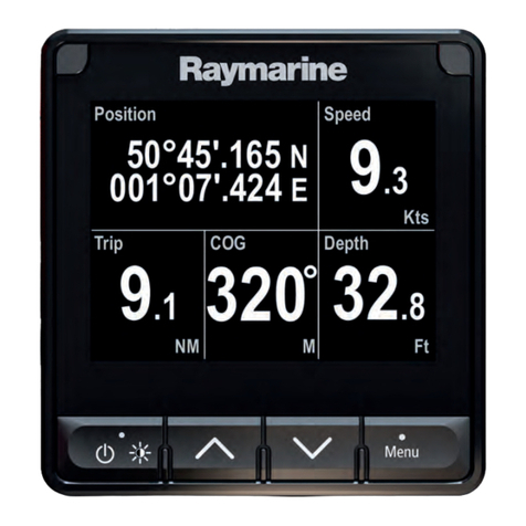
digital display UDA 100
version 2.1.1

2
promesstec GmbH I Niedersachsenstraße 4 I D- 48465 Schüttorf I Tel.:+49 (0)5923/ 90 229 0 I Fax:+49 (0)5923/ 90 229 29
E-Mail: office@promesstec.com I Internet: www.promesstec.com
Content
1. General ............................................................................................................... 3
1.1 For information .............................................................................................. 3
1.2 Signs and abbreviations................................................................................ 3
2. transport, packaging and storage......................................................................... 5
2.1 transport........................................................................................................ 5
2.2 packaging...................................................................................................... 5
2.3 storage .......................................................................................................... 5
3. Safety rules......................................................................................................... 6
3.1 Intended use of the product........................................................................... 6
3.2Personnel qualification .................................................................................. 7
3.3 Special hazards............................................................................................. 7
4. Commissioning and operation............................................................................. 8
4.1 Before mounting............................................................................................ 8
4.2 Calibration and adjustment / operation in normal mode ................................ 8
5. front- and back layout........................................................................................... 9
6. Programmable LED indicator UDA 100.............................................................. 10
7. Applications........................................................................................................ 11
8. Electrical specifications...................................................................................... 12
9. Connections....................................................................................................... 18
10. Block diagram .................................................................................................... 19
11. Routing diagram................................................................................................. 21
12. Scrolling help text............................................................................................... 22
13. configuration / operating the function keys......................................................... 25
13.1 documentation for routing diagram........................................................... 25
13.2 further explanations.................................................................................. 25
13.3 Graphic depiction of the relay function setpoint........................................ 26
14. Maintenance, Dismounting, Return, Liability, Cleaning and Disposal ............... 27
14.1 Maintenance, Dismounting....................................................................... 27
14.2 Return ...................................................................................................... 27
14.3 Liability..................................................................................................... 27
14.4 Cleaning................................................................................................... 27
14.5 Disposal ................................................................................................... 28
15. Installation.......................................................................................................... 28
16. order code.......................................................................................................... 29

3
promesstec GmbH I Niedersachsenstraße 4 I D- 48465 Schüttorf I Tel.:+49 (0)5923/ 90 229 0 I Fax:+49 (0)5923/ 90 229 29
E-Mail: office@promesstec.com I Internet: www.promesstec.com
1. General
1.1 For information
-These operating manual provides important information on handling the
measuring element. A prerequisite for safe working is compliance with all
specified safety notes and instructions for action.
-The qualified personnel must have read and understood these operating manual
before mounting and starting up the sensor.
-These operating manual is a component part of the product. Therefore, keep
them in a place that is accessible to all users at all times, close to the place of
use.
-The local regulations and safety rules applicable to the area of application of the
sensor must be observed.
-If the serial number on the type label is no longer readable (e.g. due to
mechanical damage), traceability is no longer ensured.
-The sensors described in the user manual are developed and manufactured
according to the newest findings. All components are subject strict quality and
environmental criteria during production.
-The manufacturer shall not be liable if damage is caused by improper use,
non-observance of these operating instructions, use of insufficiently qualified
personnel and unauthorized modifications to the sensor.
1.2 Signs and abbreviations
Warning!
Non-observance can lead to injuries to persons and/or destruction of
the device. There may be danger to life.
Attention!
Non-observance can lead to incorrect operation of the device or
damage to property.
Information!
Non-observance can influence the operation of the device or cause
undesired device reactions.
Danger!
If the safety instructions are not observed, there is a risk of serious or
fatal injury from electric current.
UDA 100

4
promesstec GmbH I Niedersachsenstraße 4 I D- 48465 Schüttorf I Tel.:+49 (0)5923/ 90 229 0 I Fax:+49 (0)5923/ 90 229 29
E-Mail: office@promesstec.com I Internet: www.promesstec.com
Warning!
A dangerous situation may possibly occur, which can lead to burns
due to hot surfaces or liquids if they are not avoided.
Warning!
This device is designed for connection to hazardous electric
voltages. Ignoring this warning can result in severe personal injury or
mechanical damage. To avoid the risk of electric shock and fire, the
safety instructions of this manual must be observed and the
guidelines followed. The specifications must not be exceeded, and
the device must only be applied as described in the following. Prior to
the commissioning of the device, this manual must be examined
carefully. Only qualified personnel (technicians) should install this
device. If the equipment is used in manner not specified by the
manufacturer, the protection provided by the equipment may be
impaired.
Warning!
Until the device is fixed, do not connect hazardous voltages to the
device. The following operations should only be carried out on a dis-
connected device and under ESD-safe conditions:
Troubleshooting the device.

5
promesstec GmbH I Niedersachsenstraße 4 I D- 48465 Schüttorf I Tel.:+49 (0)5923/ 90 229 0 I Fax:+49 (0)5923/ 90 229 29
E-Mail: office@promesstec.com I Internet: www.promesstec.com
Triangle with exclamation mark: Read the manual before installation
and commissioning of the device in order to avoid incidents that could
lead to personal injury or mechanical damage. Warning / demand.
Potentially lethal situations.
The CE-Mark proves the compliance of the device with the essential
requirements of the directives.
The double insulation symbol shows that the device is protected by
double or reinforced insulation.
2. transport, packaging and storage
2.1 transport
Inspect the device for any damage that may have occurred during transport. Report
obvious damage immediately.
2.2 packaging
Do not remove the packaging until immediately before assembly. Keep the packa-
ging, because it provides optimal protection during transport (e. g. changeable in-
stallation location, return).
2.3 storage
Avoid the following influences during longer storage:
-Direct sunlight or close to hot objects
-Mechanical vibration, mechanical shock (hard set up)
-Soot, steam, dust and corrosive gases
If possible, store the device in the original packaging or appropriate packaging.

6
promesstec GmbH I Niedersachsenstraße 4 I D- 48465 Schüttorf I Tel.:+49 (0)5923/ 90 229 0 I Fax:+49 (0)5923/ 90 229 29
E-Mail: office@promesstec.com I Internet: www.promesstec.com
3. Safety rules
Further important safety instructions can be found in the individual
chapters.
Definitions:
Hazardous voltages have been defined as the ranges: 75 to 1500 Volt DC, and
50 to 1000 Volt AC.
Technicians are qualified persons educated or trained to mount, operate, and also
trouble-shoot technically correct and in accordance with safety regulations.
Operators, being familiar with the contents of this manual, adjust and operate the
knobs or potentiometers during normal operation.
Receipt and unpacking:
Unpack the device without damaging it and check whether the device type
corresponds to the one ordered. The packaging should always follow with the
device until this has been permanently mounted.
3.1 Intended use of the product
Environment:
Avoid direct sun light, dust, high temperatures, mechanical vibrations and shock, rain
and heavy moisture. If necessary, heating is excess of the stated limits for ambint
tempertures should be avoided by way of ventilation. All devices fall under installation
categor II, pollution degree 2, and insulation class II.

7
promesstec GmbH I Niedersachsenstraße 4 I D- 48465 Schüttorf I Tel.:+49 (0)5923/ 90 229 0 I Fax:+49 (0)5923/ 90 229 29
E-Mail: office@promesstec.com I Internet: www.promesstec.com
3.2 Personnel qualification
Risk of injury due to insufficient qualification. Improper handling can
lead to considerable personal injury and property damage.
The activities described in these operating instructions may only be
performed by qualified personnel with the following qualifications
carry out.
Keep unqualified personnel away from the hazardous areas.
For mounting and commissioning of the sensor, these persons must be familiar with
the applicable country-specific directives and standards, and have the appropriate
qualification. You must have knowledge of measurement and control technology, be
familiar with electrical circuits and be able to carry out the work described and
recognize possible hazards independently. Depending on the operating conditions,
other knowledge may also be required, e.g. about aggressive media.
3.3 Special hazards
Observe the country-specific regulations (e.g. standards) and, in the
case of special applications, observe the applicable standards and
directives (e.g. for hazardous media such as Acetylene, flammable
or toxic substances as well as refrigeration plants and compres-
sors).
If the relevant regulations are not observed, serious personal
injury and damage to property may result!
Electrostatic discharge (ESD) protection is required. Proper use of
grounded work surfaces and personal wrist straps is required when
working with open circuits (printed circuit boards) to prevent damage
to sensitive electronic components from electrostatic discharge.
There is danger to life from electric current. There is an immediate
risk of death if live parts are touched. Installation and mounting of
electrical equipment may only be carried out by qualified electricians.
When operating with a defective power supply unit (e.g. short-circuit
from mains voltage to output voltage), life-threatening voltages can
result at the device.
Residual media in devices that have been removed can be
hazardous to persons, the environment and equipment. Sufficient
safety precautions are to be taken. This device must not be used in
safety or emergency stop devices. Incorrect applications of the de-
vice can lead to injuries. In the case of a fault, aggressive media at
extreme temperatures and under high pressure or vacuum may be
present at the device.

8
promesstec GmbH I Niedersachsenstraße 4 I D- 48465 Schüttorf I Tel.:+49 (0)5923/ 90 229 0 I Fax:+49 (0)5923/ 90 229 29
E-Mail: office@promesstec.com I Internet: www.promesstec.com
4. Commissioning and operation
4.1 Before mounting
Check whether a complete digital display has been supplied.
Inspect the device for any transport damage that may have
occurred. If such damage is present, notify the carrier and supplier
immediately. Keep the packaging, as it provides optimum protection
during transport. Make sure that the housing and the connection
contacts are not damaged.
4.2 Calibration and adjustment / operation in normal mode
Calibration and adjustment
During calibration and adjustment, the measuring and connection of external
voltages must be carried out according to the specifications of this manual. The
technician must use tools and instruments that are safe to use.
Normal operation
Operators are only allowed to adjust and operate devices that are safely fixed in pa-
nels injury and damage. This means there is no electrical shock hazard, and the de-
vice is easily accessible.

9
promesstec GmbH I Niedersachsenstraße 4 I D- 48465 Schüttorf I Tel.:+49 (0)5923/ 90 229 0 I Fax:+49 (0)5923/ 90 229 29
E-Mail: office@promesstec.com I Internet: www.promesstec.com
5. front- and back layout
front UDA 100:
back UDA 100:

10
promesstec GmbH I Niedersachsenstraße 4 I D- 48465 Schüttorf I Tel.:+49 (0)5923/ 90 229 0 I Fax:+49 (0)5923/ 90 229 29
E-Mail: office@promesstec.com I Internet: www.promesstec.com
6. Programmable LED indicator UDA 100
• 4-digit 14-segment LED indicator
• input for mA, V, potentiometer, Ohm, RTD and TC
• 2 relays and analog output
• universal voltage supply
• front key programmable
Application
•Display of digital readout of current, voltage, resistance, temperature or
potentiometer signals.
•Process control with 2 pairs of potential-free relays and / or analog output.
•For local readout in extremely wet atmospheres with a specially designed
splash-proof cover.
Technical characteristics
•4-digit LED indicator with 13,8 mm 14-segment characters. Max. display readout
-1999…9999 with programmable decimal point, relay ON / OFF indication.
•All operational parameters can be adjusted to any application by use of the front
keys.
•the UDA100 is available fully-configured acc. to specifications ready for process
control and visualisation.
•Help texts in eight languages can be selected via a menu item.
•Inputs, outputs, and supply are floating and galvanically separated.
•In versions with relay outputs the user can minimise the installation test time by
activating / deactivating each relay independently of the input signal.
Mounting
•To be mounted in front panel. The included rubber packing must be mounted
between the panel cutout hole and the display front to obtain a protection degree
of IP65. For extra protection in extreme environments, the UDA 100 can be
delivered with a speially designed splash-proof cover as accessory.

11
promesstec GmbH I Niedersachsenstraße 4 I D- 48465 Schüttorf I Tel.:+49 (0)5923/ 90 229 0 I Fax:+49 (0)5923/ 90 229 29
E-Mail: office@promesstec.com I Internet: www.promesstec.com
7. Applications
Input signals:
Output signals:
Supply:

12
promesstec GmbH I Niedersachsenstraße 4 I D- 48465 Schüttorf I Tel.:+49 (0)5923/ 90 229 0 I Fax:+49 (0)5923/ 90 229 29
E-Mail: office@promesstec.com I Internet: www.promesstec.com
Order details
UDA 100-B-A = 2 relays
UDA 100-B-B = analog output and 2 relays
NB! Please order the splash-proof cover seperately.
8. Electrical specifications
Environmental conditions
Ambient operating temperature range. . . . . . . . . . . . -20°C to +60°C
Calibration temperature . . . . . . . . . . . . . . . . . . . . . . . 20°C…28°C
Humidity . . . . . . . . . . . . . . . . . . . . . . . . . . . . . . . . . . .< 95% RF (non-cond.)
Protection degree (mounted in panel) . . . . . . . . . . . .IP65
Mechanical specifications
Dimensions (HxWxD) . . . . . . . . . . . . . . . . . . . . . . . . .48 x 96 x 120 mm
Cutout dimensions . . . . . . . . . . . . . . . . . . . . . . . . . . .44,5 x 91,5 mm
Weight . . . . . . . . . . . . . . . . . . . . . . . . . . . . . . . . . . . . 230 g
Wire size, pin 41...46 max. . . . . . . . . . . . . . . . . . . . . 0,05...1,31 mm2/ AWG
30...16 stranded wire
Wire size, other max. . . . . . . . . . . . . . . . . . . . . . . . . .0,05...3,31 mm2/ AWG
30...12 stranded wire
Vibration . . . . . . . . . . . . . . . . . . . . . . . . . . . . . . . . . . .IEC 60068-2-6
2...13,2 Hz . . . . . . . . . . . . . . . . . . . . . . . . . . . . . . . . .±1 mm
13,2...100 Hz. . . . . . . . . . . . . . . . . . . . . . . . . . . . . . . .±0,7 g
Common specifications
Supply voltage, universal. . . . . . . . . . . . . . . . . . . . . . .21,6...253 VAC, 50...60 Hz
or 19,2...300 VDC
Type
International power dissipation
Max. required power
UDA 100-B-A
2,7 W
3,0 W
UDA 100-B-B
3,2 W
3,5 W
Isolation voltage, test /operation . . . . . . . . . . . . . . . . .2,3 kVAC / 250 VAC
Signal / noise ratio . . . . . . . . . . . . . . . . . . . . . . . . . . Min. 60 dB (0...100 kHz)
Response time (0...90%, 100...10%), programmable:
Temperature input . . . . . . . . . . . . . . . . . . . . . . . . . . . 1…60 s
Current / voltage input . . . . . . . . . . . . . . . . . . . . . . . . 0,4…60 s
Accuracy, the greater of the general and basic values:
General values
Input type
Absolute accuracy
Temperature coefficient
All
≤±0,1% of reading
≤±0,1% of reading / °C

13
promesstec GmbH I Niedersachsenstraße 4 I D- 48465 Schüttorf I Tel.:+49 (0)5923/ 90 229 0 I Fax:+49 (0)5923/ 90 229 29
E-Mail: office@promesstec.com I Internet: www.promesstec.com
Basic values
Input type
Basic accuracy
Temperature coefficient
mA
≤ ±4 µA
≤± 0,4 µA / °C
Volt
≤ ±20 µV
≤± 2 µV / °C
Pt100
≤ ±0,2°C
≤ ± 0,01°C / °C
Linear resistance
≤ ± 0,1°Ω
≤ ± 0,01°Ω / °C
Potentiometer
≤ ± 0,1°Ω
≤ ± 0,01°Ω / °C
TC type:
E, J, K, L, N, T, U
≤± 1°C
≤ ± 0,05°C / °C
TC type: R, S,
W3, W5, LR
≤± 2°C
≤ ± 0,2°C / °C
TC type: B
85…200°C
≤ ± 4°C
≤ ± 0,4°C / °C
TC type: B
200…1820°C
≤± 2°C
≤ ± 0,2°C / °C
EMC - Immunity influence. . . . . . . . . . . . . . . . ≤ ± 0,5% of readout
Auxiliary supply:
2-wire supply, pin 46...45 . . . . . . . . . . . . . . . . . . . . . . . . . . . . 25...15 VDC / 0...20 mA
TC input
Type
Min. value
Max. value
Standard
B
E
J
K
L
N
R
S
T
U
W3
W5
LR
0°C
-100°C
-100°C
-180°C
-200°C
-180°C
-50°C
-50°C
-200°C
-200°C
0°C
0°C
-200°C
+1820°C
+1000°C
+1200°C
+1372°C
+900°C
+1300°C
+1760°C
+1760°C
+400°C
+600°C
+2300°C
+2300°C
+800°C
IEC 60584-1
IEC 60584-1
IEC 60584-1
IEC 60584-1
DIN 43710
IEC 60584-1
IEC 60584-1
IEC 60584-1
IEC 60584-1
DIN 43710
ASTM E988-90
ASTM E988-90
GOST 3044-84
Cold Junction compensation (CJC) via internal sensor. . . . . . . ±(2,0°C + 0,4°C * Δt)
Δt = Internal temperature –ambient temperature

14
promesstec GmbH I Niedersachsenstraße 4 I D- 48465 Schüttorf I Tel.:+49 (0)5923/ 90 229 0 I Fax:+49 (0)5923/ 90 229 29
E-Mail: office@promesstec.com I Internet: www.promesstec.com
Sensor error detection, all TC types . . . . . . . . . . . . . . . . . . . . . Yes < ±1,0 °C
Sensor error current:
when detecting. . . . . . . . . . . . . . . . . . . . . . . . . . . . . . . . . . . . . . Nom. 2 μA
else. . . . . . . . . . . . . . . . . . . . . . . . . . . . . . . . . . . . . . . . . . . . . . . 0 μA
RTD, linear resistance and potentiometer input
Input type
Min. value
Max. value
Standard
PT10…PT1000
Ni50…Ni1000
Cu10…Cu100
Lin. R
Potentiometer
-200°C
-60°C
-200°C
0 Ω
10 Ω
+850°C
+250°C
+260°C
10000 Ω
100 kΩ
IEC 60751
DIN 43760
= 0,00427
-
-
input for RTD types:
Pt10, Pt20, Pt50, Pt100, Pt200, PT250, Pt300, Pt400, Pt500, Pt1000
Ni50, Ni100, Ni120, Ni1000, Cu10, Cu20, Cu50, Cu100
Cable resistance pr. wire, RTD (max.) . . . . . . . . . . . . . . . .50 Ω
Sensor current, RTD . . . . . . . . . . . . . . . . . . . . . . . . . . . . . Nom. 0,2 mA
Effect of sensor cable resistance (3- / 4-wire), RTD . . . . . < 0,002 Ω / Ω
Sensor error detection, RTD . . . . . . . . . . . . . . . . . . . . . . . Ja
Short curcuit detection, RTD. . . . . . . . . . . . . . . . . . . . . . . < 15 Ω
Current input
Measurment range. . . . . . . . . . . . . . . . . . . . . . . . . . . . . . . 0...23 mA
Programmable measurment ranges. . . . . . . . . . . . . . . . . . 0...20 and 4...20 mA
Input resistance . . . . . . . . . . . . . . . . . . . . . . . . . . . . . . . . Nom. 20 Ω + PTC 25 Ω
Sensor error detection:
loop break 4...20 mA . . . . . . . . . . . . . . . . . . . . . . . . . . . . Yes
Voltage input:
Measurment range. . . . . . . . . . . . . . . . . . . . . . . . . . . . . . .0...12 VDC
Programmable measurment ranges. . . . . . . . . . . . . . . . . .0...1 / 0,2...1 / 0...10 /
2...10 VDC
Input resistance . . . . . . . . . . . . . . . . . . . . . . . . . . . . . . . . Nom. 10 MΩ
Outputs
Display
Display readout . . . . . . . . . . . . . . . . . . . . . . . . . . . . . . . . -1999...9999 (4 digits)
Decimal point. . . . . . . . . . . . . . . . . . . . . . . . . . . . . . . . . . Programmable
Digit height . . . . . . . . . . . . . . . . . . . . . . . . . . . . . . . . . . . . 13,8 mm
Display updating . . . . . . . . . . . . . . . . . . . . . . . . . . . . . . . . 2,2 times / s
Input outside input range is indicated by . . . . . . . . . . . . . .Explanatory text

15
promesstec GmbH I Niedersachsenstraße 4 I D- 48465 Schüttorf I Tel.:+49 (0)5923/ 90 229 0 I Fax:+49 (0)5923/ 90 229 29
E-Mail: office@promesstec.com I Internet: www.promesstec.com
Current output
Signal range (span). . . . . . . . . . . . . . . . . . . . . . . . 0...23 mA
Programmable signal ranges . . . . . . . . . . . . . . . . 0...20 / 4...20 / 20...0 /20...4 mA
Load (max.) . . . . . . . . . . . . . . . . . . . . . . . . . . . . . ≤ 800 Ω
Load stability . . . . . . . . . . . . . . . . . . . . . . . . . . . . ≤ 0,01% of span / 100 Ω
Sensor error detection . . . . . . . . . . . . . . . . . . . . . 0 / 3,5 / 23 mA / none
NAMUR NE 43 up / downscale . . . . . . . . . . . . . . 23 mA / 3,5 mA
Output limitation:
On 4…20 and 20…4mA signals. . . . . . . . . . . . . . 3,8…20,5mA
On 0…20 and 20…0mA signals. . . . . . . . . . . . . . 0…20,5mA
Current limit. . . . . . . . . . . . . . . . . . . . . . . . . . . . . .≤ 28 mA
Relay outputs
Relay function. . . . . . . . . . . . . . . . . . . . . . . . . . . . Setpoint
Hysteresis . . . . . . . . . . . . . . . . . . . . . . . . . . . . . . .0...100%
On and Off delay. . . . . . . . . . . . . . . . . . . . . . . . . . 0...3600 s
Sensor error detection. . . . . . . . . . . . . . . . . . . . . .Make / Break / Hold
Max. voltage . . . . . . . . . . . . . . . . . . . . . . . . . . . . .250 VAC / VDC
Max. AC current. . . . . . . . . . . . . . . . . . . . . . . . . . 2 A
Max. AC power. . . . . . . . . . . . . . . . . . . . . . . . . . . 500 VA
Max. DC current, resistive load:
@ URelay ≤ 30 VDC . . . . . . . . . . . . . . . . . . . . . . . . 2 ADC
@ URelay > 30 VDC . . . . . . . . . . . . . . . . . . . . . . . .[1380 x U-2Relay x 1,0085URelay] ADC
Graphic depiction of [1380 x U-2Relay x 1,0085URelay]:

16
promesstec GmbH I Niedersachsenstraße 4 I D- 48465 Schüttorf I Tel.:+49 (0)5923/ 90 229 0 I Fax:+49 (0)5923/ 90 229 29
E-Mail: office@promesstec.com I Internet: www.promesstec.com
Sensor error detection / Sensor error detection outside range
Sensor error check in UDA 100 variants
Variant
Configuration
Sensor error detection
UDA 100-B-A
ERR1=NONE, ERR2=NONE:
OFF
else:
ON
UDA 100-B-B
ERR1=NONE, ERR2=NONE,
O.ERR=NONE:
OFF
else:
ON
Outside range readout (IN.LO, IN.HI):
If the valid range of the A/D converter or the polynomial is exceeded.
Input
Range
Readout
Limit
VOLT
0...1 V / 0,2...1 V
IN.LO
< -25 mV
IN.HI
> 1,2 V
0...10 V / 2...10 V
IN.LO
< -25 mV
IN.HI
> 12 V
CURR
0...20 mA / 4...20 mA
IN.LO
< -1,05 mA
IN.HI
> 25,05 mA
POTM
-
IN.LO
< -0,5%
IN.HI
> 100,5%
TEMP
TC / RTD
IN.LO
< temperature range -2°C
IN.HI
> temperature range +2°C
LIN. R
0...800 ohm
IN.LO
< 0 ohm
IN.HI
> 1 kohm
0...10 kohm
IN.LO
< 0 ohm
IN.HI
> 15 kohm
Sensor error detection (SE.BR, SE.SH)
Input
Range
Readout
Limit
CURR
Loop break (4...20 mA)
SE.BR
<= 3,6 mA; > = 21 mA
TEMP
TC
SE.BR
> ca. 750 kohm / (1,25 V)
RTD, 2-, 3- & 4-wire, No SE.SH for
Cuxx, Pt10, Pt20 and Pt50
SE.BR
> 12 kohm
SE.SH
< 15 ohm
LIN. R
0...800 ohm
SE.BR
> 875 ohm
0...10 kohm
SE.BR
> 12 kohm

17
promesstec GmbH I Niedersachsenstraße 4 I D- 48465 Schüttorf I Tel.:+49 (0)5923/ 90 229 0 I Fax:+49 (0)5923/ 90 229 29
E-Mail: office@promesstec.com I Internet: www.promesstec.com
Display readout below min. / above max. (-1.9.9.9, 9.9.9.9)
Input
Range
Readout
Limit
CURR
VOLT
All
-1.9.9.9
Display readout <-1999
9.9.9.9
Display readout > 9999
LIN. R
All
-1.9.9.9
Display readout <-1999
9.9.9.9
Display readout > 9999
POTM
-
-1.9.9.9
Display readout <-1999
9.9.9.9
Display readout > 9999
Readout at hardware error
Error search
Readout
Cause
Text of Internal communication µC / ADC
HW.ER
Permanent error in ADC
Test of internal CJC sensor
CJ.ER
CJC sensor defect
Checksum test of the configuration in RAM
RA.ER
Error in RAM
Checksum test of the configuration in the EEPROM
EE.ER
Error in EEPROM
! Error Indications in the display blink once a second. The help text explains the error.

18
promesstec GmbH I Niedersachsenstraße 4 I D- 48465 Schüttorf I Tel.:+49 (0)5923/ 90 229 0 I Fax:+49 (0)5923/ 90 229 29
E-Mail: office@promesstec.com I Internet: www.promesstec.com
9. Connections
Inputs:
outputs:
Supply:

19
promesstec GmbH I Niedersachsenstraße 4 I D- 48465 Schüttorf I Tel.:+49 (0)5923/ 90 229 0 I Fax:+49 (0)5923/ 90 229 29
E-Mail: office@promesstec.com I Internet: www.promesstec.com
10. Block diagram

20
promesstec GmbH I Niedersachsenstraße 4 I D- 48465 Schüttorf I Tel.:+49 (0)5923/ 90 229 0 I Fax:+49 (0)5923/ 90 229 29
E-Mail: office@promesstec.com I Internet: www.promesstec.com
Table of contents
Other promesstec Monitor manuals


