manuals.online logo
Brands
  1. Home
  2. •
  3. Brands
  4. •
  5. Parker
  6. •
  7. Monitor
  8. •
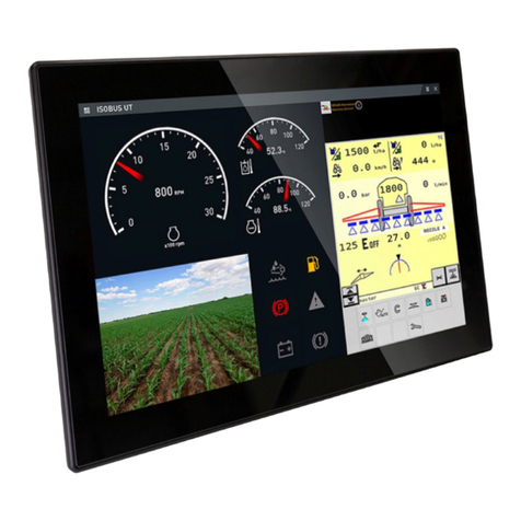
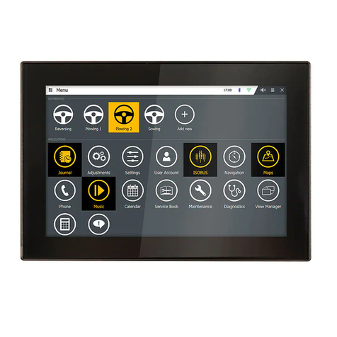
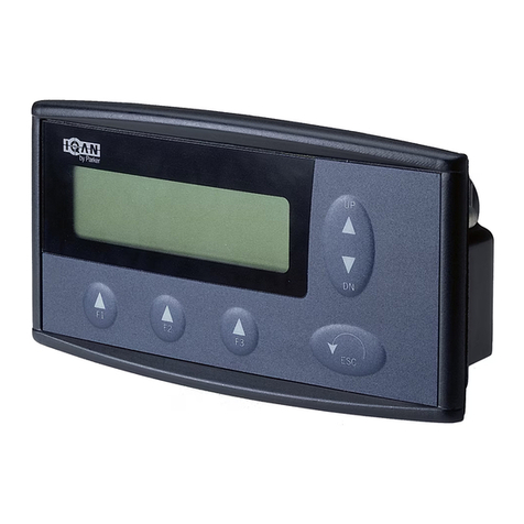
  9. Parker Pro Display 10 User manual

Parker Pro Display 10 User manual

FAILURE OR IMPROPER SELECTION OR IMPROPER USE OF THE PRODUCTS AND/OR
SYSTEMS DESCRIBED HEREIN OR RELATED ITEMS CAN CAUSE DEATH, PERSONAL
INJURY AND PROPERTY DAMAGE.
This document and other information from Parker Hannifin Corporation, its subsidiaries and authorized distributors
provide product and/or system options for further investigation by users having technical expertise. It is important that
you analyze all aspects of your application, including consequences of any failure, and review the information concerning
the product or system in the current product catalogue. Due to the variety of operating conditions and applications
for these products or systems, the user, through its own analysis and testing, is solely responsible for making the final
selection of the products and systems and assuring that all performance, safety and warning requirements of the
application are met.
The products described herein, including without limitation, product features, specifications, designs, availability and
pricing, are subject to change by Parker Hannifin Corporation and its subsidiaries at any time without notice.
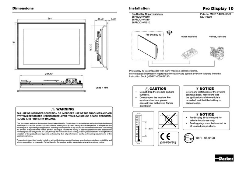
Pro Display 10
Dimensions
valves, sensors
Pro Display 10
Publ.no: HY33-4020-IS/UK
Ed. 10/2016
(2014/30/EU)
60
80
100
125
20
0
-20
-40
-40 - +85°C
40
WARNING
Eng.no:
units = mm
NOTICE
• Pro Display 10 is intended for
vehicle in-cab use only.
• Sealing plugs must be inserted in
all unused pin positions.
other modules
264
181
5,3046,20
163,20
244,40
CAUTION
• Do not drop the module on hard
surfaces.
• Do not open the module. For
repair and service, please
contact your authorized Parker
distributor.
Installation
Pro Display 10 is compatible with many machine control systems.
More detailed information regarding connectivity and system overview is found from the
Instruction Book (HY33-4020-IB/UK).
E17 10-R-040108
NOTICE
Before any installation of the system
can take place, make sure that
the ignition lock of the vehicle is
turned off and that the battery is
disconnected.
Pro Display 10
Panel Mounting
Installation
246,4 ±0,5
165 ±0,5
R2 ±0,5 (4x)
Panel cutout dimensions
Ordering Part numbers:
Panel Mounting Kit with Bracket, Pro Display 10 88PMK2PROD10
RAM 1” Mount Kit (incl. 2 bases, a double socket arm, screws and washers) 65RAM1KIT
Mounting with a bracket / Rear mounting
The device can be mounted in a panel cutout using a
bracket, which is designed for a panel thickness of 2
to 4 mm including an optional gasket (compressed). The
enclosure has blind holes with a maximum thread depth of
7.5 mm. If the spacer is not used the screw length should
be 6 mm. Longer screws may damage the device when
tightened.
Torque 2,7 Nm
The panel mounting kits include a gasket. Gasket is not provided with the device. Attach gasket
on to device ange to provide sealing towards the panel. Mount the device on to a smooth and at
surface. Device fastening to an uneven surface will stress the plastic housing. Stress may loosen
the glass from ange or damage the outer ange. Fastening on rough or uneven surface affect the
sealing performance.
4 pcs:
Screw M4x6 DIN7985
Step 1 Place the device to panel cutout and push
the device lightly.
Step 2 Fasten the bracket with screws from the
backside.
CAUTION
The torque recommendation need
to be followed.
Mounting Options
I
Mounting with RAM Mount
Mounting with RAM ball allows adjustment of the
display’s position and angle. The enclosure has
blind holes with a maximum thread depth of 7,5
mm. Longer screws may damage the device when
tightened.
Torque 2,7 Nm
4 pcs:
Screw M4x10 DIN7985
Washer M4 DIN125A
1” RAM ball base
(RAM-B-202)
1” RAM double socket
arm (RAM-B-201)
1” RAM ball base
(RAM-B-202)
Pin Signal/Function Pin Signal/Function
1 GND 7 WAKE-UP
2 CAN1_L 8 CAN4_H
3 CAN2_L 9 CAN3_H
4 CAN3_L 10 CAN2_H
5 CAN4_L 11 CAN1_H
6IGNITION_INPUT 12 +VBATT (SUPPLY)
C2
C1
C3
C4
C5
C6
ANT
C1
1
2
3
4
5
67
8
9
10
11
12
C2
12
11
10
9
8
7
6
5
4
3
2
1
C3
C4
C5
C6
Pin Signal/Function Pin Signal/Function
1 RS232_RXD_2 7 HSIDE_OUT
2 RS232_TXD_2 8 AUDIO_LINE_IN_R
3 GND 9 AUDIO_LINE_IN_L
4 AUDIO_LINE_OUT_L 10 MIC_N
5 AUDIO_LINE_OUT_R 11 MIC_P
6GND 12 MIC_BIAS
Mating connector: Housing, Deutsch DTM06-12SA;
Terminals, Deutsch 1062-20-0222;
Sealing plugs, Deutsch 0413-204-2005
Recommended cable: 0,75 - 1,0 mm2 (AWG 18)
Mating connector: Housing, Deutsch DTM06-12SB;
Terminals, Deutsch 1062-20-0222;
Sealing plugs, Deutsch 0413-204-2005
Recommended cable: 0,75 - 1,0 mm2 (AWG 18)
Pin Signal/Function
1 5V_USB1
2 USB1-
3 USB1+
4 GND
5 SHIELD
Mating connector:
M12-4pin male, D-coded (available
from several manufacturers).
Pin Signal/Function
1 5V_USB0
2 USB0-
3 USB0+
4 GND
5 SHIELD
Mating connector:
M12-4pin male, D-coded (available
from several manufacturers).
Pin Signal/Function
1 CVBS_IN1
2 12V_CAM
3 GND
4 CVBS_IN2
5 GND
6 SHIELD
Mating connector:
M12-5pin male, A-coded (available
from several manufacturers).
Pin Signal/Function
1 TX+
2 RX+
3 TX-
4 RX-
5 SHIELD
Mating connector:
M12-4pin male, D-coded (available
from several manufacturers).
Pro Display 10Wiring diagram Installation
Pin Signal/Function
1 GND
2 AERIAL
Mating connector:
SMA male (available from several
manufacturers).
Radio Antenna Connection (available in part# 88PROD10AD10 /
88PROD10AS10):
AN
T
Pro Display 10InstallationPrototype installation cables
Description Parker ordering number
C1 Cable 2,5 meters, grey, key A 50301251
C2 Cable 2,5 meters, black, key B 50301261
Connector Kit C1 & C2, grey & black, A + B 200730811
1 These IQAN accessories are compatible with Pro Display 10. Check the latest order
information from IQAN Accessories catalogue (HY33-8319/UK) always before placing
an order.
Communication cables
Description Parker ordering number
FAKRA to SMA
antenna
Adapter cable 0,2 meters 50301841
Ethernet Cable 1,5 meters 200777801
Ethernet Adapter cable, panel mount, 1,5 meters 200777851
USB Cable M12 - USB, 1,5 meters 88CABPRODUSB
NOTICE
Micro SD card slot must be always
protected with a cover plug.
Micro SD Card Installation
Installation of Micro SD card to Pro Display:
Step 1 Remove the cover plug. You may need a small coin or preferably a screwdriver with a
size 3 standard head for opening the cover.
Step 2 Place Micro SD card into a slot as presented in the drawing above (the contacts are
towards the product label).
Step 3 Push the Micro SD card evenly into the slot bottom.
Step 4 Secure the Micro SD card slot with cover plug. Tighten the plug lightly with small coin
or screwdriver to prevent it loosening during operation, and maintain IP rating of the
device.

Other manuals for Pro Display 10

2

This manual suits for next models

2

Other Parker Monitor manuals

Parker Pro Display 10 User manual

Parker

Parker Pro Display 10 User manual

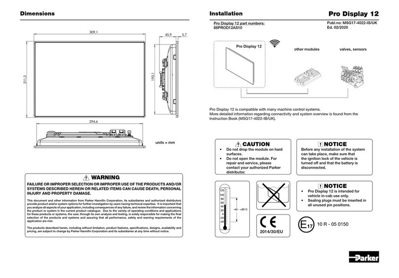
Parker PRO DISPLAY 12 User manual

Parker

Parker PRO DISPLAY 12 User manual

Parker 71-313 Series User manual

Parker

Parker 71-313 Series User manual

Parker IQAN MDM User manual

Parker

Parker IQAN MDM User manual

Parker 71-113 Series User manual

Parker

Parker 71-113 Series User manual

Parker IQAN-MD4 User manual

Parker

Parker IQAN-MD4 User manual

Parker SciCon II Assembly instructions

Parker

Parker SciCon II Assembly instructions

Parker PHM 17" TFT User manual

Parker

Parker PHM 17" TFT User manual

Parker Airtek DB1000 Owner's manual

Parker

Parker Airtek DB1000 Owner's manual

Parker PHD Series User manual

Parker

Parker PHD Series User manual

Parker Pro Display 10 User manual

Parker

Parker Pro Display 10 User manual

Parker PHD28 User manual

Parker

Parker PHD28 User manual

Parker 71-213 Series User manual

Parker

Parker 71-213 Series User manual

Parker IQAN-MD3 User manual

Parker

Parker IQAN-MD3 User manual

Parker PRO DISPLAY 12 User manual

Parker

Parker PRO DISPLAY 12 User manual

Popular Monitor manuals by other brands

ViewSonic VE510s-4 Service manual

ViewSonic

ViewSonic VE510s-4 Service manual

Toshiba 65H84 brochure

Toshiba

Toshiba 65H84 brochure

Philips 247E6 user manual

Philips

Philips 247E6 user manual

Samsung SyncMaster 323T user manual

Samsung

Samsung SyncMaster 323T user manual

Panasonic TH-47LFT30W brochure

Panasonic

Panasonic TH-47LFT30W brochure

Acer V206HQL Guide

Acer

Acer V206HQL Guide

Itek ITMF40I141WQHD user manual

Itek

Itek ITMF40I141WQHD user manual

AOC 712Swa-1 user manual

AOC

AOC 712Swa-1 user manual

Watchman 9-90 owner's manual

Watchman

Watchman 9-90 owner's manual

Sony SDM-HS74 Service manual

Sony

Sony SDM-HS74 Service manual

Asus VX279Q user guide

Asus

Asus VX279Q user guide

Philips BDL5530EL user manual

Philips

Philips BDL5530EL user manual

Iiyama ProLite E1706S-1 user manual

Iiyama

Iiyama ProLite E1706S-1 user manual

GVision K19BH-F Specifications

GVision

GVision K19BH-F Specifications

Sony PVM-L2300 Operation manual

Sony

Sony PVM-L2300 Operation manual

MicroTouch OF-100P-A1 user manual

MicroTouch

MicroTouch OF-100P-A1 user manual

Samsung SyncMaster 400UXN-3 user manual

Samsung

Samsung SyncMaster 400UXN-3 user manual

Zenith MU-50PZ41V owner's manual

Zenith

Zenith MU-50PZ41V owner's manual

manuals.online logo
manuals.online logoBrands
  • About & Mission
  • Contact us
  • Privacy Policy
  • Terms and Conditions

Copyright 2025 Manuals.Online. All Rights Reserved.