PROMIX RDS.01 User manual

16-07-2019
1
OPERATING MANUAL
Technical description. Installation manual. Certificate.
ПШБА.464415.101 РЭ
Check the completeness of the product upon purchase! The manufacturer will
not accept any further claims for completeness.
1.
PURPOSE
Remote control system Promix-RDS is designed for radio remote control of various actuators
(electromagnetic, electromechanical locks, latches; turnstiles, etc.).
The system includes: actuator, power supply unit, receiver, controller unit, remote controls. The
power supply unit, receiver, and controller unit are designed as a single unit (controller
Promix-
CR.RX.03, hereinafter – the controller). The receiver of the controller receives control signals of
remote controls
Promix-CR.TX.01. The power supply unit of the controller is used to control the
connected actuators.
2.
DELIVERY SET
Controller Promix-CR.RX.03 1 pc.
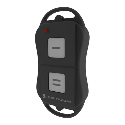
Remote control Promix-CR.TX.01 with a battery 2 pcs.
Operating manual 1 pc.
3.
CLIMATIC OPERATING CONDITIONS OF THE
CONTROLLER
•
resistance to climatic factors according to GOST15150-69:УХЛ4;
•
ambient air temperature: from -30 to +50 °С;
•
relative air humidity not more than 80% at +25 °С and lower temperatures without
condensation and frost formation.
REMOTE CONTROL SYSTEM
Promix-RDS.01

Promix-RDS.01
2
4.
TECHNICAL DATA
4.1 TECHNICAL DATA OF THE POWER SUPPLY UNIT
The power supply unit of the controller powers the receiver, controller unit, and actuator. The
power supply unit is a pulse type, with galvanic isolation of primary and secondary circuits. The
power supply unit has a built-in overcurrent and short-circuit protection for the load circuit.
Supply voltage (50 Hz), V 180-230
Output voltage (direct current), V 12
Rated output current, A
1.0
Maximum output current during 1 minute, А, not more than
1.5
Maximum load current (tripping current), A, not more than
2.0
4.2 TECHNICAL DATA OF THE CONTROLLER UNIT
The controller unit is designed on the same board as the receiver. The controller unit performs
the following functions:
•
programming of remote controls and control time of the actuator;
•
applying or removing supply voltage to/from the actuator for a specified time on the signals
of the programmed remote controls;
•
disconnecting the actuator from the power supply unit (protection) when the current
consumption by the actuator exceeds the preset level;
•
audible signaling of the controller current operations.
Supply voltage (direct current), V 12
Current consumption, mA 5
Protection tripping current (disconnection of the actuator), A
2.0
Memory capacity of the remote controls, pcs.
7
Range of programmed open lock time, s
1-15
4.3 TECHNICAL DATA OF THE RECEIVER
Supply voltage (direct current), V 12
Current consumption, mA 2
Operating frequency, MHz
433.92
Sensitivity, µV
7
Reception range of signals from the remote control Promix-CR.TX.01 (in
direct visibility and absence of interference), m, not less than
30

Promix-RDS.01
3
Since the controller can stay in this mode for an indefinite time, make sure that
actuator connected to the controller can be supplied with power for a long
time.
4.4 TECHNICAL DATA OF THE REMOTE CONTROL
PROMIX-CR.TX.01
Output power, мW, not more than 10
The length of the code, byte 4
Number of code combinations
16777216
Battery supply voltage (type 23А), V
12
Current consumption with pressed button, мА, not more than
5
5.
DESIGN AND PRINCIPLE OF OPERATION
The controller Promix-CR.RX.03 contains: a connector for connection of the actuator, a mode
jumper J1, a power cord for connection to 220V power grid (1.4 m long), an antenna wire. The
overall dimensions of the controller Promix-CR.RX.03: 111x58x50 mm (LxWxH).
When pressing the control button on the remote control Promix-CR.TX.01, it sends a unique
code via a radio channel. The controller Promix-CR.RX.03 receives the sent code and, if this code
is recorded in the controller memory (see Section 7), activates its output contact for the
programmed time (the supply voltage is applied to or removed from the actuator), what is
accompanied by a continuous beep signal.
If the current in the circuit of the actuator exceeds the value of the tripping current, the power
supply will switch off. It can be restored by reconnecting the controller to the power grid. The state
of the controller after the current protection trips is indicated by short intermittent sound signals.
When holding down the remote control button for more than 7 seconds, the controller switches
into the permanently open actuator mode. The controller emits a short trill and then produces
single beeps. To close the actuator, press the remote control button. The controller will close the
actuator and emit a beep signal.

Promix-RDS.01
4
Avoid applying excessive supply voltage. Ensure reliable electrical contact.
Insulate connections to prevent short circuits.
6.
CONNECTION
Connect the actuator to the controller terminals, observing the polarity of the supply voltage: the
left terminal is positive, and the right one is negative. To do so, press the orange lever of the
terminal block with a screwdriver and, holding it pressed, insert the wire into the hole. To
disconnect the wire, perform the same procedure.
Connect the controller to 220V power grid.
Jumper J1 (see Fig. 1 in Section 5) on the side wall of the controller is to change its operating
modes:
Position 1 or 2
– control of normally open or normally closed actuator;
A normally open actuator is in the open state when there is no supply voltage and in the closed
state when the supply voltage is applied.
A normally closed actuator is in the closed state when there is no supply voltage and in the
open state when supply voltage is applied.
Position 3
– programming of the controller.
7.
PROGRAMMING THE CONTROLLER
The supplied remote controls are already recorded in the controller memory. The factory
setting of the controller parameters: control time is 5 seconds, control of the normally closed
actuator.
There are two ways of programming the controller: remote - carried out with the master remote
control Promix-CR.TX.01 M (supplied separately), non-remote - carried out by placing the jumper
J1 to position
3
.
Non-remote programming:
1. Place the jumper J1 to position
3
(see the figure in Section 5).
2. Connect the power cord to the power grid.
3. After a trill and then single beeps, proceed to programming
Fig.1. Diagramof the controller connection

Promix-RDS.01
5
After entering the programming mode all the previously recorded remote
controls will be deleted from the controller memory. The programmed time of
the open lock time remains saved.
While the controller is in the programming mode, the lock is turned off.
To avoid accidental reprogramming of the controller and deleting of the
database of programmed remote controls, make sure you move the jumper J1
from position 3 to position 1 or 2 after programming is complete.
4. Press the remote control button, wait for a sound signal, confirming recording of the remote
control number into the controller memory.
5. Program next remote control by repeating step 4. When 7 remote controls are recorded you
will hear a trill. If fewer remote controls are to be programmed, wait until the end of single
beeps and confirmation of the end of remote controls programming.
6. Wait for 5 seconds. In 5 seconds the controller switches into the actuator control time
programming mode what is confirmed by two beeps. Then the controller emits double short
beeps, during which the programming is carried out.
7. Pressing the button of the programmed remote control increases the open lock time by 1
second. The set time (in seconds) corresponds to the number of beeps.
8. If no action is performed during 5 seconds, the controller switches from the programming
mode into the operating mode, confirming it with three beeps.
9. Determine the type of the connected actuator (normally open or normally closed) (see
Section 6).
Remote programming:
1. Connect the power cord to the power grid.
2. Press the button of the master remote control Promix-CR.TX.01 M (supplied separately)
within 5 seconds.
3. After a trill and then single beep sounds, proceed to programming according to the
aforementioned algorithm, starting from step 4.
8.
FUNCTIONAL CHECK USING THE EXAMPLE
OF ELECTRICALLY-CONTROLLED LOCK
Connect the controller to 220V power grid and close the door with an installed electrically-
controlled lock.
1. Try to open the door. It should not open.
2. Press the button of the remote control Promix-CR.TX.01 programmed in the controller, after
a beep sound the lock will be open for the programmed time. The door should open. After
the beep ends, the lock will be closed again.

Promix-RDS.01
6
9.
MAINTENANCE
The controller: special maintenance is not required.
The remote control: if the LED does not light up or glows dimly it is necessary to replace the
battery of the remote control. To replace the battery, unscrew the screw on the back of the remote
control and disassemble the body.
10.
REQUIREMENTS OF SAFETY AND
ENVIRONMENTAL ENGINEERING
Promix-RDS set meets the safety requirements as per GOST R IEC 60065-2009.
Installation and operation of the controller Promix-CR.RX.03 must meet the safety
requirements as per GOST 12.2.003-91.
The controller Promix-CR.RX.02 meets the fire safety requirements as per GOST 12.1.004-91.
Promix-RDS.01 set is not hazardous for life and health of people and for environment. After the
expiration of the service life, the set can be disposed of without any special environmental
protection measures.
10.1 ELECTRICAL SAFETY REQUIREMENTS
Due to low supply voltage the remote control Promix-CR.TX.01 is electrically safe.
Electrical safety requirements for the controllers Promix-CR.RX.02 meet the requirements of
protection against electric shock according to class II as per GOST R IEC 60065-2009.
The insulation strength between the current-carrying circuits of the mains supply and the
secondary circuits with a low-voltage complete device must withstand an AC voltage of 3750V of
practically sinusoidal form with a frequency of 50±1 Hz. The electrical insulation resistance
between the current-carrying circuits of the mains supply and the secondary circuits, depending on
the climatic operating conditions, must be at least of the following values:
- with a low-voltage complete device - 10 MOhm;
- at the highest value of temperature - 4 MOhm;
- at the highest value of relative humidity (98% at 25°С) - 1 MOhm.
The residual voltage between the pole contacts of the power cord must not exceed 31V one
second after disconnecting from the power grid.
In the controller Promix-CR.RX.02 there are no circuits that lead to leakage currents.
11.
STORAGE AND TRANSPORTATION
Prior to putting into operation, the products must be stored in the manufacturer’s packing, in
rooms with ambient air temperature of -30 to +50 °С and relative humidity not higher than 98% at
25 °С according to the storage conditions as per GOST 15150-69.
The products transportation conditions must comply with group C under GOST 23216-78 in
terms of exposure to mechanical factors, and Ж2 under GOST 15150-69 in terms of exposure to
climatic factors.

Promix-RDS.01
7
The warranted operation period of the products is 12 months from the date of
sale but not longer than 18 months from the day of acceptance by the
manufacturer’s QCD.
The warranty does not cover the batteries included in the set.
Faulty products are accepted for repair only complete, with the compulsory
preservation of the factory labels on the body of the products.
To improve the quality of the product, the manufacturer reserves the right to
make changes in the design of products without prior notice.
12.
WARRANTY LIABILITIES
The manufacturer, ETC PROMIX LLC, warrants conformity of the products to requirements of
current technical specifications provided that the transportation, storage, installation and operation
rules established in this Manual are followed.
Within the period of warranty, ETC PROMIX LLC undertakes to eliminate defects of the system
components, caused by the Manufacturer's fault, or to replace defective components and units
free of charge. Costs of delivery to and from the place of repair shall be borne by the Buyer.
Warranty liabilities do not cover any defects and damages caused by:
•
Improper maintenance by the Buyer;
•
Use of the products under conditions that do not comply with the operation requirements;
•
Mechanical damages or disassembly of the products by the Buyer;
•
Non-observance of the transportation and storage rules.
After the expiration of the warranty service period, the manufacturer provides post-warranty
service of the product on a contractual basis.
13.
ACCEPTANCE AND PACKING CERTIFICATE
The remote control system
PROMIX-RDS.01
in quantity of ___ pieces (1 peace by default) bearing the
manufacturing date and QCD mark on the body is manufactured and accepted according to
ПШБА.464415.101 ТУ, meets the obligatory requirements of state standards and current technical
documentation, is recognized fit for operation and packed by ETC PROMIX LLC.
Engineering and Technical Center PROMIX LLC
Russia, 214030, Smolensk, Krasninskoye shosse, 35, letter A
Tel. (4812) 619-330
www.promix-center.com
www.facebook.com/Promixcenter
mail@promix-center.com
This manual suits for next models
2
Table of contents
