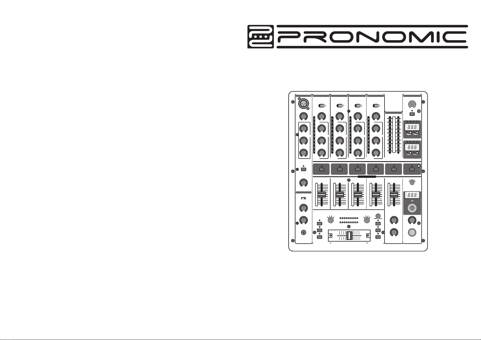
Pronomic DJM500 User manual
P lea s e r ea d t his m a n u a l c a r ef u lly a nd p ro per t a k e c a r e o f t his m a nua l
MI C C H A NN E L 1
L INE / C D P HONO/ C D P HONO/ L IN E P HONO/ L IN E
MA ST E R L E V E L
S U R R OU N D
MIN MAX
-12dB
+ 12dB
T R IM
HI G H
-12dB + 12dB
-12dB + 12dB
MI D
L OW
E Q
MIN MAX
-32dB + 12dB
T R IM
HI G H
-32dB + 12dB
-32dB + 12dB
MI D
L OW
E Q
MIN MAX
-32dB + 12dB
T R IM
HI G H
-32dB + 12dB
-32dB + 12dB
MI D
L OW
E Q
MIN MAX
-32dB + 12dB
T R IM
HI G H
-32dB + 12dB
-32dB + 12dB
MI D
L OW
E Q
MIN MAX
-32dB + 12dB
T R IM
HI G H
-32dB + 12dB
-32dB + 12dB
MI D
L OW
E Q
MIN MAX
ON
+ 7
+ 4
+ 2
0
-2
-4
-7
-10
-20
-30
L R
A1 2 3 4
SY NC
L OC K
B E A T
AS S I ST
B1 2 3 4
SY NC
L OC K
B E A T
AS S I ST
C H- 1 C H- 2 C H - 3 C H - 4 MA ST E R E F F E CT S
10
9
8
7
6
5
4
3
2
1
0
10
9
8
7
6
5
4
3
2
1
0
10
9
8
7
6
5
4
3
2
1
0
10
9
8
7
6
5
4
3
2
1
0
10
9
8
7
6
5
4
3
2
1
0
C F C U R V E
1
23
4
T E M P O D IF F E R EN CE
T IM E O F FS ET
HI
MI D
L O
K I L L A
HI
MI D
L O
K I L L B
1
23MIC
MASTER
4
S OU R CE
MI C O N
OFF MAX
T A L K
CUE MASTER
MI X
MIN MAX
L E V E L
P H ONE S
MO D E
STEREO SPLIT
P R OG R A M
S C R O L L P US H
S E L E CT
MIN MAX
L E V E L
LEFT RIGHT
B O OT H L E V E L
MIN MAX
MA ST E R B A L A N C E
E F F E CT S O N
A S S IG N A A S S IG N B
1
23
4
MONIT O R
+7
+4
+2
0
-2
-4
-7
-10
-20
-30
+7
+4
+2
0
-2
-4
-7
-10
-20
-30
+7
+4
+2
0
-2
-4
-7
-10
-20
-30
+7
+4
+2
0
-2
-4
-7
-10
-20
-30
A V C A C ON T R OL L E D C R OS S F A D E R B
C HA N NE L 2 C HA N NE L 3 C HA N NE L 4
M ON IT O R C U E
DJM500 5 Channel DJ-Mixer

EQUALIZER
DIGITAL EFFECTS PROCESSOR
SYSTEM SPECIFICATIONS
POWER SUPPLY
DIMENSIONS/WEIGHT
Stereo Low +12 dB/-32 dB @ 50 Hz
Stereo Mid +12 dB/-32 dB @ 1.2 kHz
Stereo High +12 dB/-32 dB @ 10 kHz
Mic Low +15 dB/-15 dB @ 80 Hz
Mic Mid +15 dB/-15 dB @ 2.5 kHz
Mic High +15 dB/-15 dB @ 12 kHz
Kill Low -54 dB @ 80 Hz
Kill Mid +44 dB @ 1 kHz
Kill High +26 dB @ 10 kHz
DSP 24-bit
A/D-D/A converter 24-bit Sigma-Delta,
64/128-times oversampling
Sampling rate 46.875 kHz
Mains voltages USA/Canada
120 V~, 60 Hz
Europe/u.k./Australia
230 V~, 50 Hz
Japan
100V~, 50-60 Hz
General export model
120/230 V~, 50-60 Hz
Power consumption 32W
Fuse 100-120 V~: T 1A H
200-240 V~: T 500 mA H
Mains connection Standard IEC receptacle
Dimensions (WxDxH) 390mmx340mmx115mm
15.354″x 13.386 x 4.528″ ″
Weight 5.5kg
(9)
Signal-to-noise ratio > 80 dB (Line)
Crosstalk > 70 dB (Line)
Distortion (THD) < 0.03%
Frequency response 10 Hz - 55 kHz, +0/3 dB
(8)
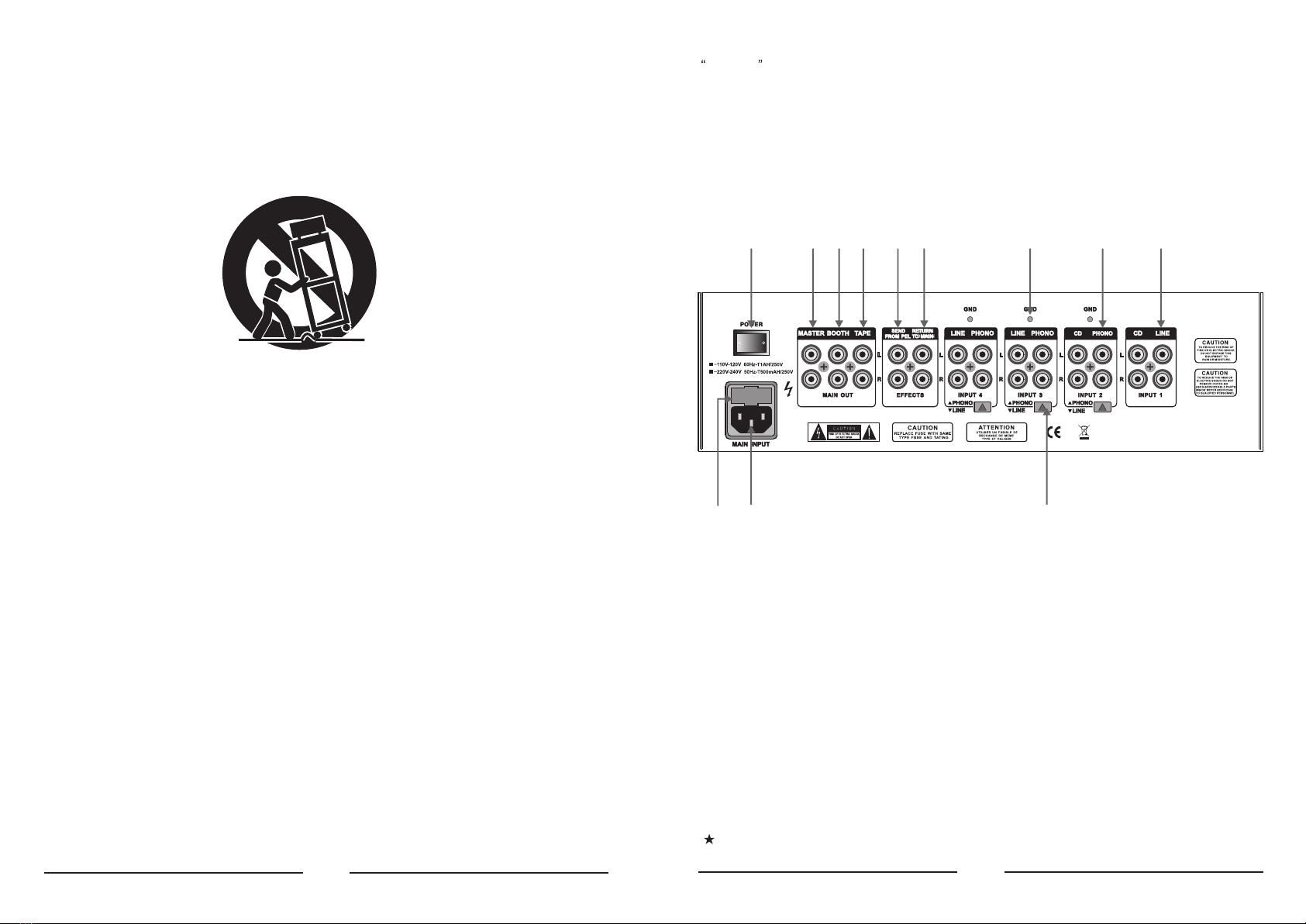
is no signal at the mixer before turning on the power amps. To be sure, slide all the faders
to the bottom and switch all controls to the zero position.
(45) The BOOTH output gives you an additional option of connecting an amplifier in order to, for
example, feed the signal into your monitors or to bring sound to an extra area. The BOOTH
output level is regulated by using the BOOTH LEVEL control (20) of the MASTER section.
(46) Using the TAPE output you can record your music by connecting devices such as tape decks,
DAT recorders etc. Unlike the MASTER output, the output volume is fixed, making it necessary
for you to adjust the input level on the recording device.
(47) The POWER switch power the mixer on. You should always make sure that the POWER switch
is in the Off position when initially connecting the unit to the mains.
(48) This is the connector for the power cable. This is where the advantage of a sophisticated int-
ernal power supply can be seen: the pulse behaviour of each amplifying circuit is mainly det-
ermined by the voltage reserves available. Each mixing console is equipped with numerous
operational amplifier (op amps) to process line level signals. Due to limited output of their p-
ower supplies, many mixing consoles show signs of stress when subjected to heavy loads.
But not your mixer: the sound is always clear and transparent.
(49) FUSE HOLDER / VOLTAGE SETTING. Before connecting the unit to the mains, ensure that
the voltage setting matches your local voltage. Blown fuses should only be replaced by a fuse
of the same type and rating. On some units, the fuses holder can be switched to on of two p-
ositions, i.e. 230 V and 120 V. Please note: should you desire to operate the unit outside Eu-
rope at 120 V, a higher fuse rating is required.
Please take note: Merely switching the unit off does not mean that it is fully disconne-
cted from the mains. When not using the unit for prolonged periods of time, please u-
nplug the unit s power cord from the power outlet.
To disconnect power from main, pull out the main cord plug. When installing the prod-
uct, ensure that the plug is easily accessible. If mounting in a rack, ensure that the ma-
ins can be easily disconnected by a plug or by an all-pole disconnect switch on or near
the rack.
3. SPECIFICATIONS
AUDIO INPUTS
Mic 40 dB Gain, XLR,
electronically balanced input stage
Phono in 40 dB Gain, unbalanced input
Line in 0 dB Gain, unbalanced inputs
CD in 0 dB Gain, unbalanced inpts
Return 0 dB Gain, unbalanced input
AUDIO OUTPUTS
Master max.+21 dBu
Booth max.+21 dBu
Tape typ. 0 dBu
Send typ. 0 dBu
Phones Out max. 180 mW @ 75Ω/1% THD
(1) Read these instructions.
(2) Keep these instructions.
(4) Follow all instructions.
(5) Do not use this device near water.
(6) Clean only with a dry cloth.
(7) Do not block any ventilation openings. Install in accordance with the manufacturer s instructions.
(8) Do not install near any heat sources such as radiators, heat registers, stoves, or other app-
aratus (including amplifiers) that produce heat.
(9) Do not defeat the safety purpose of the polarized or grounding-type plug. A polarized plug
has two blades with one wider than the other. A grounding type plug has two blades and a
third grounding prong. The wide blade or the third prong are provided for your safety. If the
provided plug does not fit into your outlet, consult an electrician for replacement of the ob-
solete outlet.
(3) Heed all warnings.
1. IMPORTANT SAFETY INSTRUCTIONS
CAUTION: To reduce the risk of electric shock, do not remove
No user serviceable parts inside; refer servicing to qualified personnel.
the top cover (or the rear section).
WARNING: To reduce the risk of fire or electric shock, do not expose this appliance to rain and
moisture.
This symbol, wherever it appears, alerts you to the presence of uninsulated dangerous
voltage inside the enclosure-voltage that may be sufficient to constitute a risk of shock.
This symbol, wherever it appears, alerts you to
instructions in the accompanying literature. Please read the manual.
important operating and maintenance
2. DETAILED SAFETY INSTRUCTIONS:
(1)
(7)
The built-in digital effects processor of your mixer can process the MASTER signal, the input
channels signal or the microphone signal. Use the SOURCE selector (33) to select the signal
on which you want to run the effects. The PROGRAM display (34) located below shows the effect
presets that can be recalled by turning and then pressing the effect presets that can be (35). The
LEVEL control (36) is used to determine the volume of the effects signal. Use the EFFECTS ON
switch (37) to turn the effects on and off.
Various effects are segmented into seven different groups, offering such standard effects as
reverb, delay, echo etc. As well as additional filter and combination effects.
2. CONNECTIONS
(38) These are the LINE i.e. CD inputs to connect a tape deck, CD or MD player etc. Unlike other
channels, channel 1 features two line inputs.
(39) The PHONO input for channels 2 to 4 are for connecting a turntable.
(40) The GND connectors ground the turntables.
(41) With the PHONO/LINE switch it is possible to switch the input sensitivity of the PHONO inputs
2 to 4 to line level. This allows you to connect a tape deck or a CD player to the PHONO inputs.
(42) The 5 channel mixer features an integrated effects loop for the connection of an external eff-
ects device. The MONITOR signal is taken at the SEND output and routed, fox example, to a
reverb processor. Thus, the signal at the SEND connector is identical to the headphones sig-
nal and is selected with the MONITOR CUE buttons (16).
(43) The externally processed signal is added to the MASTER output signal via the RETURN co-
nnectors. The effect signal volume may only be adjusted at the output control of the effects
device itself.
(44) The MASTER output is for connecting to an amplifier and can be adjusted with the MASTER
fader (18).
Always turn the power amps on last to avoid inrush currents that can easily damage your
speakers. And, to avoid sudden and unpleasant surprises for your ears, make sure there
(38)(39)(40)(43)(42)(46)(45)
(48) (41)
(44)(47)
(49)
(10) Protect the power cord from being walked on or pinched particularly at plugs, extension
cords, and the point at which they exit the unit.
(11) Only use attachments/accessories specified by the manufacturer.
(13) Unplug this device during lightning storms or when not used for long periods of time.
(14) Refer all servicing to qualified service personnel. Servicing is required when the unit has
been damaged in any way, such as power supply cord or plug is damaged, liquid has b-
een spilled or objects have fallen into the device, the unit has been exposed to rain or
moisture, does not operate normally, or has been dropped.
(12) Use only with the cart, stand, tripod, bracket, or table specified by the manufacturer, or
sold with the device. When a cart is used, use caution when moving the cart/ device
combination to avoid injury from stumbling over it.
(2)
MI C CH ANNE L 1
LI N E/CD PH O NO/C D P HONO/ LINE PH O NO/L I NE
MA ST E R LEVE L
SU R ROUN D
MIN M AX
-12 dB
+12dB
TR I M
HI G H
-12 dB +12dB
-12 dB +12dB
MI D
LO W
EQ
MIN M AX
-32 dB +12dB
TR I M
HI G H
-32 dB +12dB
-32 dB +12dB
MI D
LO W
EQ
MIN M AX
-32 dB +12dB
TR I M
HI G H
-32 dB +12dB
-32 dB +12dB
MI D
LO W
EQ
MIN M AX
-32 dB +12dB
TR I M
HI G H
-32 dB +12dB
-32 dB +12dB
MI D
LO W
EQ
MIN M AX
-32 dB +12dB
TR I M
HI G H
-32 dB +12dB
-32 dB +12dB
MI D
LO W
EQ
MIN M AX
ON
+7
+4
+2
0
-2
-4
-7
-10
-20
-30
L R
A1 2 3 4
SYN C
LO C K
BE AT
AS SI ST
B1 2 3 4
SYN C
LO C K
BE AT
AS SI ST
CH - 1 CH - 2 CH - 3 CH- 4 MA ST E R EFFE CT S
10
9
8
7
6
5
4
3
2
1
0
10
9
8
7
6
5
4
3
2
1
0
10
9
8
7
6
5
4
3
2
1
0
10
9
8
7
6
5
4
3
2
1
0
10
9
8
7
6
5
4
3
2
1
0
CF CURVE
1
23
4
TE MP O DI FF ER E NCE
TI ME O FFS ET
HI
MI D
LO
KI L L A
HI
MI D
LO
KI L L B
1
23MIC
MAS TER
4
SO U RCE
MI C O N
OFF M AX
TA LK
CUE M ASTER
MI X
MIN M AX
LE V EL
PH O NES
MO DE
STE REO SPL IT
PR O GRAM
SC RO L L PU SH
SE LECT
MIN M AX
LE V EL
LEF T RIGHT
BO OTH LEVE L
MIN M AX
MA ST E R BA L ANCE
EF F ECTS ON
AS S IGN A AS S IGN B
1
23
4
MO N IT O R
+7
+4
+2
0
-2
-4
-7
-10
-20
-30
+7
+4
+2
0
-2
-4
-7
-10
-20
-30
+7
+4
+2
0
-2
-4
-7
-10
-20
-30
+7
+4
+2
0
-2
-4
-7
-10
-20
-30
A VC A C ONTR O LLED CRO S SFAD E R B
CH A NNEL 2 CH A NNEL 3 CHANN E L 4
MONITO R CUE
(6)
BEAT ASSIST buttons, the difference in tempo from both channels is illustrated in the form of
a ninecharacter message on the TEMPO DIFFERENCE-LED (24). The extent of the difference
in tempo is indicated by a corresponding swing to the right (signal A is slower) or to the Left
(signal B is slower). When the middle LED lights up, the tempi are the same. The TIME OFF-
SET LED (23) below that displays the signal A and B synchronisation. Should the middle LED
light up, the tracks are synchronised. Should the display move to the left or right, the channels
are not synchronised. The TEMPO DIFFERENCE and TIME OFFSET displays are only active
if the tempi of both channels have been fixed in one of the ways described.
When no signal is present (or when the signal level is too low), the BPM display shows
only dashes. When the signal is present but can not be identified, the display shows 160
BPM and the shows the said dashes. The beat counter then attempts to get another re-
adout. Therefore, 160 BPM is no usable value; rather, it is simply an error message whten
the signal can not be analyzed.
To exit the SYNC LOCK or BEAT ASSIST modes, simply push the SYNC LOCK button once
more on both channels.
1.8 Internal effects processor
EFF
10
11
12
13
14
15
20
21
22
23
24
25
26
27
28
29
A
B
30
31
32
33
34
Reverb Big Plate
Reverb Small Chamber
Reverb Bright Room
Reverb Voice Widener
Reverb Phil s Drums
Reverb Short Delay
Delay 1/2 95 BPM
Delay 3/4 95 BPM
Delay 1/1 95 BPM
Delay 1/2 110 BPM
Delay 3/4 110 BPM
Delay 1/1 110 BPM
Delay 1/2 124 BPM
Delay 3/4 124 BPM
Delay 1/1 124 BPM
Delay 1/2 131 BPM
Delay 3/4 131 BPM
Delay 1/1 131 BPM
Echo 1/2 95 BPM
Echo 3/4 95 BPM
Echo 1/1 95 BPM
Echo 1/2 110 BPM
Echo 3/4 110 BPM
EFF
35
36
37
38
39
A
B
40
41
42
43
44
50
51
60
61
62
70
71
72
73
74
75
Echo 1/1 110 BPM
Echo 1/2 124 BPM
Echo 3/4 124 BPM
Echo 1/1 124 BPM
Echo 1/2 131 BPM
Echo 3/4 131 BPM
Echo 1/1 131 BPM
Flanger Stereo Flanger
Flanger Vintage Flanger
Flanger Dual Phaser
Flanger Rotary Speaker
Flanger Stereo Chorus
Panning Panning
Panning Tremolo
Filter Auto Filter
Filter LFO Filter
Filter Vinylizer
Sim/Dyn Ultrabass
Sim/Dyn Ultrafex
Sim/Dyn Voice Changer
Sim/Dyn Tube Amp
Sim/Dyn Blues
Sim/Dyn Radio Speaker
(3)
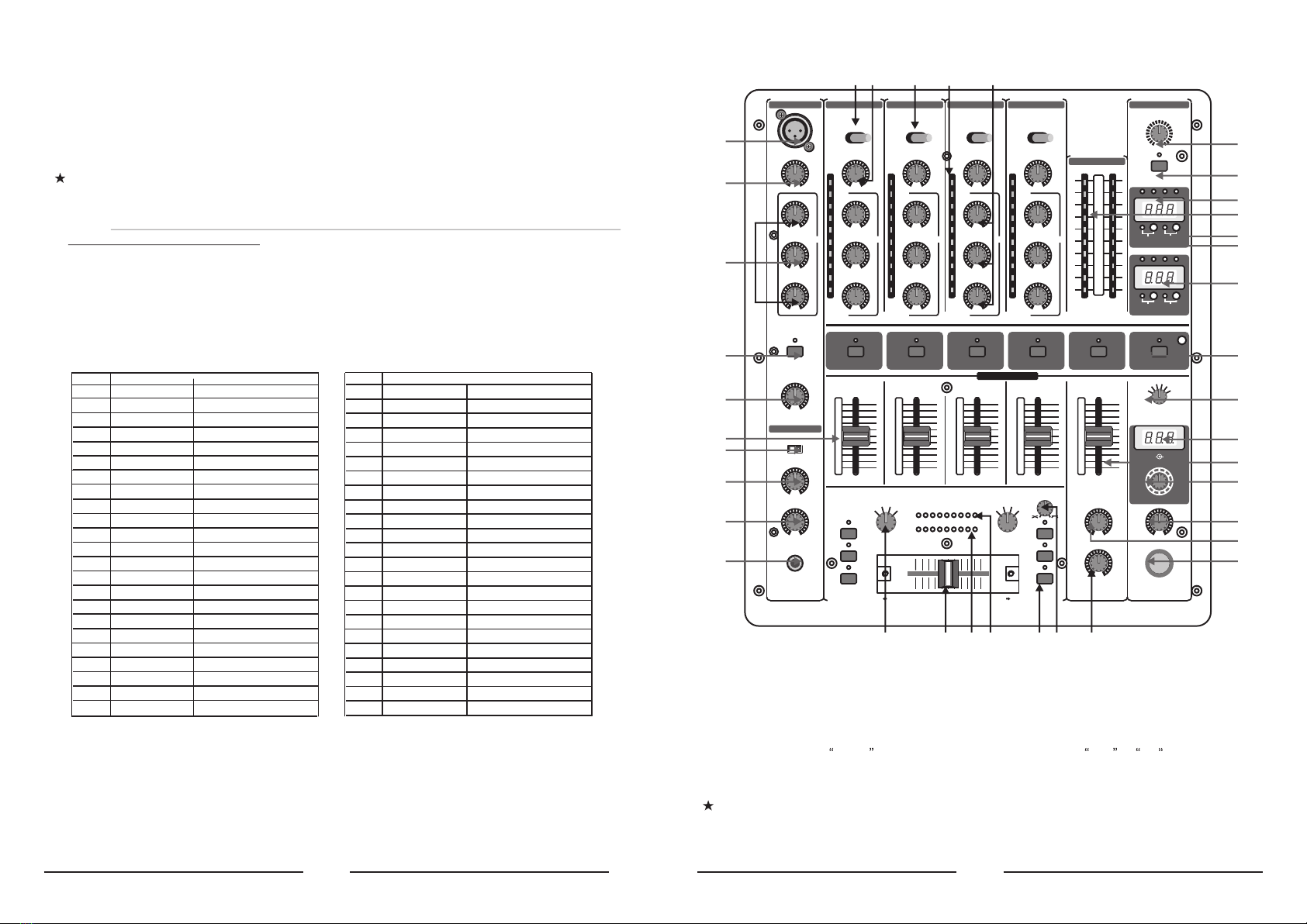
1. CONTROL ELEMENTS
(1) (3) (2) (5) (4)
(6)
(7)(7)
(8)
(9)
(10)
(11)
(16)
(17)
(18)
(37)
(36)
(35)
(33)
(30)
(34)
(32)
(27)
(28)
(29)
(31)
(19)
(12)
(13)
(14)
(15)
(20)(21) (22) (23) (24) (26)(25)
1.1 Stereo channels 1 to 4
(1) Use the LINE/CD switch to select the input signal for channel 1. Unlike other channels, channel 1
features two line inputs.
(2) You determine the input signals for the channels 2 to 4 with the PHONO/CD i.e. PHONO/LINE switch
(channels 3 and 4). Phono is intended for connecting a turntable. Line i.e CD must be selected
for all other signal sources (e.g. CD or MD players). The input sensitivity of the phono input can be
switched to line level, allowing utmost flexibility (see(41)).
Never connect devices with line level to the highly sensitive phono inputs! The output
level of phono pick-up systems is measured in millivolts, whereas CD players and tape
decks have levels measured in volts, i.e.the level from line signals is up to 100 times
higher than that of the phono inputs.

(5)
(18) The MASTER fader allows you to adjust the output volume at the MASTER output (see (44)).
(19) The MASTER BALANCE control for the MASTER output is for setting the stereo image.
(20) The BOOTH LEVEL control adjusts the output level of the BOOTH output (see (45)).
1.5 CROSSFADER section
(21) ASSIGN A and ASS/GN B selectors let you determine which input signals are routed to
CROSSFADER sides A and B You can also alternate between these two signals by using the
CROSSFADER (see below).
(22) The VCA CONTROLLED CROSSFADER is used to fade between the channels you have selec-
ted (see (21). Like the channel faders, the crossfader section is equipped with a professional 45-
mm fader.
(23) The TIME OFFSET LED indicates the synchronisation of tracks (see chapter 2.7)
(24) The TEMPO DIFFERENCE LED displays tempo differences between the tracks (see chapter
2.7).
(25) A 3-band kill switch is available for use with both the left and the right side of the crossfader
(KILL A and KILL B respectively). Kill switches are used to lower three separate frequency
ranges (LOW, MID and HIGH) up to -32 dB. When using the kill switch, the equalizer of ordi-
nary DJ mixers usually loses its functionality. Not the case with the 5 channel mixer: the EQS
can be used to achieve an even more pronounced lowering of a particular frequency range.
(26) The CF CURVE control lets you alter the control characteristic of the crossfader between
linear and logarithmic in an infite number of steps. When set to linear, the crossfader enga-
ges directly proportionally to the fader s incremental movement. When set to logarithmic, the
fader s movement yields higher volume increases as the fader moves farther along its range
of motion.
1.6 3D surround effect
The 3D surround function is a built-in effect that puts the finishing touch to your music and
turns every gig into a real experience. The widening of the stereo base makes for a livelier,
more transparent sound. You can determine the intensity of the effect by using the SURROUND
control (27), while the ON switch (28) turns the effect on (the respective LED is lit).
1.7 Auto BPM counter
The integrated auto BPM counter is an extremely useful feature. It ensures smooth transition
from one track to the next, taking a lot of the guesswork out. It can calculate the various temp-
os of tracks in BPM(beats per minute). Both BPM counter sections are identical and both show
the BPM value of the two signals routed to the crossfader. The LEDs located above the DISPL-
AYs 1-4 (29) indicate which of the four input channels are routed to the respective BPM counter.
The tempo of the track assigned by using the ASSIGN A or ASSIGN B keys is shown in the
respective DISPLAY (30) Several tempo changes in one track would produce a constant displ-
ay of various BPM values and thus lead to unnecessary confusion. That s why the beat count-
er sections each have a SYNC LOCK button (31) that can be used during the song to limit the
range of possible tempo values. This makes sense if the counter has already calculated a rea-
listic value. You can do the same thing manually with the BEAT ASS/ST button (32). Pushing
this button at least three times in sync with the song s tempo results in the calculated tempo
appearing in the DISPLAY. The BEAT ASSIST and SYNC LOCK buttons are each equipped
with a LED.
When you have limited the tempo of the tracks on both channels with the SYNC LOCK or
(4)
(3) The TRIM control in the CHANNEL section is used to adjust the level of the input signal. The
level meter (5) reads the input level.
(4) Each of the input channels features a 3-band equalizer (HI, MID and LOW) with kill characte-
ristic. Thus, the signal can be attenuated to a much greater extent (-32 dB) than it can be rai-
sed (+12 dB). This function can be very useful when, for example, fading a frequency range
out of a music track.
The overall level also depends on the EQ setting. Thus, you should adjust the equalizer
before setting the input gain with the TRIM control.
(5) The 10-digit LED chains display the signal level of the input signals.
(6) Adjust the channel volume using the CHANNEL fader.
1.2 Microphone channel
(7) The MIC IN connector is the balanced XLR input for your dynamic microphone.
(8) Set the volume of the microphone signal with the TRIM control in the MIC section.
(9) There is a 3-band equalizer (HI, MID and LOW, no kill characteristic) in the microphone
section. This allows you to fine-tune your voice to adapt perfectly to your sound.
(10) Activate the microphone channel using the MIC ON switch. The channel is active when the
corresponding LED is lit.
(11) The PRO MIXER is equipped with a talkover function, which works very simply: if you speak
into the microphone while a track is running, the volume of the music is automatically reduced,
so that your voice is always in front . The TALK control allows you to determine how much
the music volume is lowered (max. -24 dB). This function can come in handy when your own
voice needs to be prominently heard, as in when making an announcement etc.
1.3 MONITOR section
The MONITOR signal is your headphones signal, allowing you to listen to music without
affecting the MASTER output signal.
(12) When the MODE switch is in the Split position, channel PFL is located on the left side of
the stereo image, while the Master signal is on the right. In this case, the MIX control (see
below) serves no function. While in Stereo mode, you can use the MIX control to alternate
between MASTER signal and PFL.
(13) When in Stereo mode, the MIX control lets you determine which signal can be heard via the
headphones. When the control is turned to its left-most position (CUE), you hear the headp-
hone signal only; when the control is turned to its right-most position, you hear the MASTER
signal only. Alternating the MIX control between the two end positions lets you dermine the
relative ratio between the two signals in your headphones.
(14) The LEVEL control determines the volume of the headphones signal.
(15) Connect you headphones using the unbalanced PHONES OUT connector. Your headphones
should have a minimum impedance of 32 Ohms.
(16) To select the PFL signal for the headphones, use the MONITOR CUE keys (CH-1 to CH-4,
MASTER, EFFECTS). You can also select multiple signal sources and listen to them simulta-
neously. LEDs on corresponding keys are lit when a channel is routed to the headphones.
1.4 MASTER section
(17) The LEVEL METER displays the level of the MASTER signal.
Table of contents
Other Pronomic Music Mixer manuals


