Propox ISPcable II User manual

ISPcable II Programer for AVR, AT89S and AT90S
Atmel microcontrollers with serial interface.
User’s Guaid
REV Beta 1.1
rter Kits Embedded Web Serve
PI microcontrollers Sta-
s for ‘51, AVR, ST
,
ation Board
Evalu
rs Prototyping Boards Minimod-
Microprocesor systems, PB
AVR, PI, ST microcontrollers
ed In System programmers for
net controllers, RFID High Spe-
ules for microcontrollers, ether-
designing Evaluation Boards for
ethernet controllers, RFID High
nimodules for microcontrollers,
Servers Prototyping Boards mi-
lers Starter Kits Embedded Web
‘51, AVR, ST, PI microcontrol-
Speed In Systems programme-
rocontrollers Starter Kits Embe-
ards for `51, AVR, ST
, PI mic-
PB designing Evaluation Bo-
ollers Microprocesor systems,
rs for AVR, PI, ST microcontrl-
dded Web Serwers Prototyping
mers for AVR, PI, ST microco-
High Speed In System program-
controllers, ethernet controllers,
Boards Minimodules for micro-
controllers Microprocesor
Boards
ning Evaluation
Systems, PB Desig-
R
Many ideas one solution

Introduction
Thank you for buying our ISPcable II programmer. We hope that the great power it
offers will allow you to appreciate fully the virtues of programming in the system provided
by Atmel microcontrollers.
ISPcable II is advanced, high-speed development/production programmer supporting
most In-System Programmable microcontrollers from Atmel. ISPcable II gives the
designer a compact and realiable programming tool to program most In-system
Programmble Atmel microcontrollers through a 6- or 10-pin ISP connector. The
programmer connects to a P through a standard RS232 serial interface and draws the
necessary power from the target board eliminating the need for an additional power
supply. Maximum speed of RS232 and SPI interfaces are chooses automaticly for
programming with maximum accessible for programmed mikrocontroller speed.
ISPcable II can co-operate with microcontrollers supplied with voltages from 1.5 to 6 V.
Such a broad range of supply voltages was achieved through buffering of signals on the
ISP line, additionally enhancing the immunity of the circuit to interference. ISPcable II is
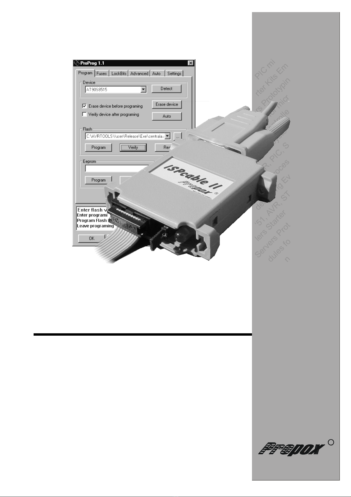
provided with ProProgRS software working in the Windows system, it co-operate with
AVRStudio (AVR Prog -not all microcontorllers) software from Atmel as well. Moreover,
functions offered by ProProgRS are available, such as: programming and read-out of
Flash memories, EEPROM, fuse-and-lock bits, RESET signal configuration, SPI
frequency.
Due to the small size, it is also an excellent tool for field upgrades of existing applications
Let us wish ou nothing but success and a lot of satisfaction in
designing and putting new microprocessor devices to work.
Features
•onnects to standard P comm port
•Fast programming with auto-adapting or manual RS232 clock
•auto-adapting or manual SPI clock
•Programming software can be easily upgraded to support future devices, if necessary.
Support will be added as soon as new devices become available.
•Operates with target voltages in the range of 1.8 - 6 V
•Buffering of the ISP bus, allowing proper operation with systems powered from a broad
range of supply voltages and enhancing immunity to external interference
•Operation of the programmmer signalized by built-in LED indicator
•Standard 10-pin connector to the target circuit in the Atmel standard
•Draws power from target, or external power
•Small size
•Supports R Oscillator alibration
•Programs both Flash and EEPROM
•Security and Fuse Bit programming supported
•EEPROM and all Fuse and Lock Bit options ISPProgrammable can be programmmed
individually or with the sequential automatic programming option
2

Features of ProProg
•Application runs under Win-95/Win-98, NT, Windows 2000, XP,Windows 2003
•High usability
•Programs both Flash and EEPROM
•Security and Fuse Bit programming supported
•Fast programming with auto-adapting or manual RS232 and SPI clock
•Automatic or manual configuration of polarization of RESET signal and S K frequency
•Support for serial production
•3 any size serial number supported
•Free software upgrade
•Extensive embedded help
Supported devices
Below is a list of devices supported by the programmer. As new devices appear, the list is going to
be modified.
AT89S tinyAVR AVR megaAVR
AT89S8252
AT89S8253
AT89S51
AT89S52
AT89S53
ATtiny12
ATtiny13
ATtiny15
ATtiny22
ATtiny26
ATtiny2313
AT90S1200
AT90S2313
AT90S2323
AT90S2333
AT90S2343
AT90S4414
AT90S4433
AT90S4434
AT90S8515
AT90S8534
AT90S8535
ATmega8
ATmega16
ATmega32
ATmega48
ATmega64
ATmega88
ATmega103
ATmega128
ATmega161
ATmega162
ATmega163
ATmega165
ATmega168
ATmega169
ATmega323
ATmega603
ATmega8515
ATmega8535
AT90CAN128
3

Times of programming
Microcontrollers Fosc
(MHz)
Flash Write (s) EEPROM Write (s)
3.3V 5V 6V 3.3V 5V 6V
AT89S8252 24 TBD TBD TBD TBD TBD TBD
AT89S8252 12 TBD TBD TBD TBD TBD TBD
AT89S8252 4 TBD TBD TBD TBD TBD TBD
AT89S53 24 TBD TBD TBD TBD TBD TBD
AT89S53 12 TBD TBD TBD TBD TBD TBD
AT89S53 4 TBD TBD TBD TBD TBD TBD
AT90S1200 12 TBD TBD TBD TBD TBD TBD
AT90S1200 1 TBD TBD TBD TBD TBD TBD
AT90S2313 12 TBD TBD TBD TBD TBD TBD
AT90S2313 1 TBD TBD TBD TBD TBD TBD
AT90S8515/8535 8 TBD TBD TBD TBD TBD TBD
AT90S8515/8535 1 TBD TBD TBD TBD TBD TBD
ATmega103 6 TBD TBD TBD TBD TBD TBD
ATmega103 1 TBD TBD TBD TBD TBD TBD
ATmega323 8 TBD TBD TBD TBD TBD TBD
ATmega323 1 TBD TBD TBD TBD TBD TBD
ATmega128 16 TBD TBD TBD TBD TBD TBD
ATmega128 1 TBD TBD TBD TBD TBD TBD
Note: The only minimum times of programming in schedule were passe for some devices
TBD – the times be become passed in next version of this users’ guaid.
Description of the programmer
Power - External power supply the programmer
RS232 - 9 D-Sub female connector for connection with the serial port of the PC
LED - Signalling of mode of programmer unit work
blinking - readiness
continuous shining - programming
Jumper - Jumper closed when supplying target from programmer
ISP - 10-pin connector to the target circuit in the Atmel standard
4
Power
RS232
LED
Jumper
ISP

VCC
GND
GND
GND
GND
MOSI
LED
RST
SCK
MISO
2
1
Programmer ISP connector
Standard 10-pin connector to the target circuit in the Atmel standard
5
OPIS WYPROWADZEŃ
MOSI SPI - sygnał danych Master wy / Slave we
LED LED diode and multiplexer signal
RST arget RESE control pin
SCK SPI - serial clock signal
MISO SPI - data signal Master in / Slave out
VCC Power supply from target circuit 1.5 - 6V
GND Programmer ground

Connection with the target circuit
The connection to the target circuit should be realized through the attached 10-lead ribbon cable,
terminated with standard IDC plugs with 2.54 mm raster. In case of using another cable it should be
kept in mind that it should not be longer than 30 cm (~12 inches). The target device should be
equipped with a ISP connector with lead-out identical to that of the programmer ISP connector. We
connect the ISP bus lines with their corresponding ISP bus lines of the microcontroller as shown
in the figure below.
Connection with the AT90S8515 microcontroller
The LED signal can also serve to switching multiplexer the separating the signals MOSI, MISO,
S K from the rest of system on time the programming. Solution such should be use in systems in
which to SPI BUS be connected different arrangements like Flash memory or RT . It eliminates the
possibility of accidental record to these arrangements in time the programming the microcontroller.
Signal LED in programming moment switch to low level. The connection using multiplexer is shown
in the figure below.
Connection with theAT90S8515 microcontroller with multiplexer
6
123456
A
B
C
D
654321
D
C
B
A
itle
N umb er R ev isio nSiz e
B
Date: 4-Ju l-200 2 Sheet o f
File: C:\Mo je dokumenty \us er\Ev b _at90.d d bDrawn By:
R ESE
9
X AL2
18
X AL1
19
GND
20
OC 1B 2 9
ALE 3 0
ICP 3 1
VC C 4 0
PC0 /A8 2 1
PC1 /A9 2 2
PC 2 /A1 0 2 3
PC 3 /A1 1 2 4
PC 4 /A1 2 2 5
PC 5 /A1 3 2 6
PC 6 /A1 4 2 7
PC 7 /A1 5 2 8
PD0/RX D
10
PD1/ X D
11
PD2/IN 0
12
PD3/IN 1
13
PD4
14
PD5 /OC 1 A
15
PD6/W R
16
PD7/R D
17
PB0/ 0
1
PB1/ 1
2
PB 2/AIN0
3
PB 3/AIN1
4
PB4/SS
5
PB5/MOSI
6
PB6/MISO
7
PB 7/SC K
8
PA0 /A D0 3 9
PA1 /A D1 3 8
PA2 /A D2 3 7
PA3 /A D3 3 6
PA4 /A D4 3 5
PA5 /A D5 3 4
PA6 /A D6 3 3
PA7 /A D7 3 2
A 9 0 S85 1 5
X0
1 2
X1
1 3
Y0
2
Y1
1
Z0
5
Z1
3
INH
6
A
1 1
B
1 0
C
9
X1 4
Y1 5
Z4
4 0 53 /7 4 HC 40 5 3
PB6
PB7
PB512
34
56
78
91 0
JP2
ISP Head er
RS
ISP A TIVE
47 0 R - 1 k
V G
V G
V G
MOSI
LED
C LK
MISO
Reset circuit
ISP m ultiplexer
123456
A
B
C
D
654321
D
C
B
A
itle
N umb er R ev isio nSi ze
B
Date: 4-Ju l-200 2 Sh eet o f
File: C:\Moje d ok u menty \us er\Ev b_at9 0.dd bDrawn By :
R ESE
9
X AL2
1 8
X AL1
1 9
GND
2 0
OC 1 B 29
ALE 30
ICP 31
VC C 4 0
PC 0 /A8 2 1
PC 1 /A9 2 2
PC2 /A1 0 2 3
PC3 /A1 1 2 4
PC4 /A1 2 2 5
PC5 /A1 3 2 6
PC6 /A1 4 2 7
PC7 /A1 5 2 8
PD0 /R XD
1 0
PD1 / X D
1 1
PD2 /IN 0
1 2
PD3 /IN 1
1 3
PD4
1 4
PD5 /OC 1 A
1 5
PD6/W R
1 6
PD7/R D
1 7
PB0 / 0
1
PB1 / 1
2
PB 2 /AIN0
3
PB 3 /AIN1
4
PB4 /S S
5
PB5 /MOS I
6
PB6 /MIS O
7
PB 7 /S C K
8
PA 0 /A D0 39
PA 1 /A D1 38
PA 2 /A D2 37
PA 3 /A D3 36
PA 4 /A D4 35
PA 5 /A D5 34
PA 6 /A D6 33
PA 7 /A D7 32
A 9 0 S 85 1 5
12
34
56
78
91 0
JP2
ISP Head er
RS
ISP A TIVE
47 0 R - 1 k
V G V G
V G
MOSI
LED
C LK
MISO
Reset circuit

Level converter of ISP signals
In order to assure proper operation of the programmer when the supply voltages of the target circuit
differ from the programmer’s supply voltage, level converters of ISP signals come into use. The
conversion circuits have been designed for operation with a target circuit supplied from a voltage
between 1.8 and 6 V.
The ISPcable II can be supplied from an external source or directly from the target circuit. In the
last case, the supply voltage should have a value between 4.5 and 5.5 V.
Signals between the programmer and the target circuit can be divided into two groups: input
signals (MISO), output (MOSI, SCK, RST, LED). Besides regenerating ISP bus signals, the signal
level converter buffers limit the input and output currents. Buffering has been applied on all signal
lines of the programmer. The implementation of a signal level converter for output
lines has been shown in the figure below.
Voltage level converter (outputs)
The implementation of a signal level converter in the input line of the MISO programmer is shown
below.
Voltage level converter (input)
7
123456
A
B
C
D
654321
D
C
B
A
itle
Number RevisionSize
B
Date: 7-Jul-2002 Sheet of
File: C:\Moje dokumenty\user\Evb_at90.ddbDrawn By:
1 2
33R
ZENER
From uC
VCC V G
To Target
ISP HEADER
V G
123456
A
B
C
D
654321
D
C
B
A
itle
Number RevisionSize
B
Date: 7-Jul-2002 Sheet of
File: C:\Moje dokumenty\user\Evb_at90.ddbDrawn By:
1 2
ZENER
o uC
VCCV G
From Target
ISP HEADER
V G
10k
33R
V G

Suppl ing the programmer
Programmer unit can be powered on two ways:
•By the ISP connector from target circuit. In this case the power voltage VTG system should
be since 4.5 to 5.5 V, Power jumper must be close.
•Bye external power supply connected to POWER of programmer. In this case power voltage
VTG system should be since 1.8 to 6V, after closing power jumper, power to the target circuit
can be supplied, the maximum current is 50 mA. However power supply programmer unit
should be done across connector about diameter of pin 2.5 mm. The Voltage should be
since 9 to 15V for D and since 7 to 13 for A .
The implementation of arrangement of the power supply inside the programmer unit ISPcable II was
showed on following drawing.
Arrangement of the power supply of programmer unit
8
1 2 3 4 5 6
A
B
C
D
654321
D
C
B
A
itle
Number RevisionSize
B
Date: 7-Jul-2002 Sheet of
File: C:\Moje dokumenty\user\Evb_at90.ddbDrawn By:
1
2
3
POWER
JUMPER
POWER
ISP HEADER
VCC V G
7805
Level conventer

Technical data
Dimensions : 55 x 53 x 16 mm
Weight : about 0,1 kg
Connection to the PC : Serial port 9-pin D-SUB female
Transmission speed : max. 115200 bit/s - negotiation speed
Programming cable : lenght 50cm
Programming connector : 10-pin connector ID 0.1’’ in Atmel standard
ISP clock frequenc : max 250kHz min 10kHz
Target circuit suppl voltage : VTG 1.8 – 6.0V
Power suppl : requires power supply from target circuit or external
form target circuit
VTG 4.5 – 5.5V Is max 50mA.
from external power suppl
Vpower 7-12 D 6-15 A Ip max 50mA
VTG 1.8 – 6.0V Is max 5mA
Contents of deliver package
I Pcable II programmer
RS232 cable for connection of the emulator with a PC
Cable terminated with IDC 10 plugs for connection of the programmer with the target circuit
CD with documentation and software
Technical assistance
Please provide the following data:
Version of programmer and ProProg software
Clock frequency and type of processor in the PC
Version of the operating system
Processor type (complete number of the device) and oscillator’s frequency
Detailed description of the problem
9
Table of contents
Other Propox Motherboard manuals