Prostage PurpleLine User manual

Prostage S.L.
•
Apdo 57
•
ES-07560 Cala Millor
•
Mallorca
info@prostage.eu
•
www.prostage.eu
PurpleLine Users Manual
Firmware Version 1.30
Stand: 18. February 2010

Page
1
Table of Contents
1.Introduction
2. Terminology
3. Connecting your System
3.1 The XTMpro
3.1.1 Power Supply
3.1.2 StageWire
3.1.3 USB
3.1.4 MIDI
3.1.5 Tap Relay
3.1.6 The Switching Relays Option (XTMpro-R only)
3.2 Setting up the XDS Drawer
3.2.1 Fitting the XDS System in your Rack
3.2.2 Fitting the Stompboxes (Pedal Effects) in the XDS
3.2.3 Connecting External Units to the XDS
3.2.4 The Power Supplies of the XDS
3.2.5 Two-Button Stompbox
3.3 The Audio Connections of XLS and XDS Loop Systems
3.3.1 Connecting the Loops
3.3.2 Tuner / Mute Function
3.3.3 Stereo
3.4 Foot Controller
3.4.1 Connecting an Expression Pedal to the Foot Controller
3.4.2 Calibration of the Expression Pedal
4. Hum
5.0 Using Your System
5.1 The Foot Controllers
5.2 The XTMpro
(with Relay Option)
5.3 The XDS and XLS Loop System
6. The Prostage System Manager Software
6.1 Installing the System Manager Software
(Mac & PC)
6.1.1 Installing the USB Driver on Mac OSX
6.1.2 Installing the USB driver on Windows
6.1.3 Running the System Manager
6.1.4 The File Menu
6.2 The “XTMpro Basic Settings” Tab
6.2.1 General Settings / Foot Controller
6.2.2 MIDI In
6.2.3 MIDI Thru Filter
6.2.4 Tap Function
6.2.5 Relay Option
6.3 The “Program Mapping” Tab
6.3.1 Basic Settings of the “Program Mapping” Table
6.3.2 De ning Mappings
6.3.3 Mapping Mode “Program Number”
6.3.4 Mapping Mode “Control Change”
6.3.5 Mapping Mode “Convert incoming CC”
6.4 The “Relays” Tab
6.5 The “Switch Assignment” Tab
6.6 The “Foot Controller Settings” Tab
6.6.1 Foot Controller List
6.6.2 Operating Modes
6.6.3 Tap Switch
6.6.4 Sidekick (X05 and X10)
6.6.5 Foot Controller Basic Settings
6.6.6 Display Settings (X05 and X10)
6.6.7 Using Default Settings
6.6.8 Rename Foot Controller
6.7 The “Remote WahWah” Tab
7. Firmware Upgrade
7.1 How to Upgrade the Firmware of the XTMpro
7.2 How to Upgrade the Firmware of a Foot Controller
8. Appendix: Signal Flow Charts of the XTMpro
9
. Warranty / Support

Page
2
1. Introduction
Dear Customer
Thank you for buying the Prostage System. You have chosed the most advanced loop and switch system available
in the world. As Prostage PurpleLine is a coherent system, this manual covers all PurpleLine units. There are no
separate manuals for a single foot controller or a loop system.
If you have any questions, or if something does not work as you expect, please do not hesitate to contact us:
info@prostage.eu. Your questions will also help us to improve this users manual.
We are also looking forward to your suggestions concerning new features. We are still working to improve the
functionality of the system. You can easily upgrade the units’ software yourself. For more information about this
topic, see chapter 7 “Firmware Upgrade”.
The philosophy on the Prostage PurpleLine system is “control without limits”. We want you to be able to setup
your system exactly as you want it to work while keeping it as simple to use as possible. Therefore, there are lots
of things inside the system you can con gure. You will note that the chapters “Connecting your System” and “The
Prostage System Manager Software” cover most pages of this manual, while the chapter “Using Your System” is
less than one page. This means, once you have con gured the system properly, you will be able control your entire
equipment with a single footstep, except of the coffee machine ;-)
2. Terminology
PurpleLine:
PurpleLine are all Prostage units which are equipped with the innovative StageWire technology (see the sections
below). The units’ color is purple. The XLR connectors are labeled “StageWire”.
BlackLine:
This are the “old” Prostage products which send a standard MIDI signal via XLR. The units are colored black.
The XLR connectors are labeled “IN” / “OUT”. BlackLine and PurpleLine foot controllers are not compatible with
each other.
StageWire:
StageWire is a technology developed by Prostage especially
to be used
on stage. StageWire is a connection that
enables several devices to communicate with each other via a standard microphone cable.
It
is four times faster
than MIDI. Using only one microphone cable from one device to another device, they can communicate with each
other in both directions (bi-directional). Furthermore, the microphone cable supplies the foot controllers with
power.
MIDI:
See www.midi.org (http://www.midi.org/aboutmidi/intromidi.pdf)
Program Change | PC:
Program Change messages are used to recall presets or switch sounds on connected devices. We use the short
form “PC” in the System Manager software for MIDI “Program Change” message. A Program Change consists of
a MIDI channel (1-16), and the program number 0-127 (most units display them as 1-128).
Control Change | CC:
Control Change messages let you call and automate parameters and functions in real time. A Control Change
message can, for example, vary the volume. The short form “CC” stands for MIDI “Control Change”; it is often
also called “Continuous Controller”. A CC message consists of a MIDI channel (1-16), a controller number and a
value 0-127.
On/Off Switches:
Besides the standard MIDI commands, StageWire also allows you to send instant access messages. They are used
for example to switch the Relays of the XTMpro. On/Off Switches work in a similar way like an analog foot switch
connected directly to your ampli er, e.g to switch channels. An On/Off Switch message consists of a MIDI channel
(1-16), a switch number (1-8) and the On/Off state.
Relay:
A remotely controlled switch.

Amp
Guitar
Tap Relay of XTMpro
Page
3
3. Connecting your System
3. Connecting your System
The Prostage System always consists of one master unit (XTMpro, XDS. XLS) and up to 14 foot controllers. In other
words, you can connect up to 15 PurpleLine units in a row. The master unit supplies the entire system with power.
The XTMpro is the “heart” of the system. XDS and XLS use the same electronics like XTMpro. This means, the
chapter “XTMpro” also applies to XDS and XLS.
IMPORTANT =>
You can connect a BlackLine foot controller to a PurpleLine master unit (XDS, XLS,XTMpro), but
you cannot connect a PurpleLine foot controller to the black XTM adaptor. Do NOT mix PurpleLine and BlackLine
foot controllers! All foot controllers must be the same color.
3.1 The XTMpro
=>
The instructions concerning “XTMpro” also apply to XDS and XLS Loop Systems!
3.1.1 Power Supply
T
he XTMpro is powered by a 9V or 12V, AC or DC power supply.
XDS and XLS loop systems are powered with 220-240VAC or 110-120VAC (see marking beside power cable).
The red LED of the XTMpro indicates that the system is on:
Blinking LED => the XTMpro is working, but no foot controller has been detected.
Solid LED => The System is working and the communication with the foot controller works properly.
LED ickers => The XTMpro receives data on StageWire input.
3.1.2 StageWire
Use a standard microphone cable
to
connect the StageWire connector of your XTMpro with the “Main” connector
of your foot controller. If you have more than one foot controller, use the “Link” connector of your rst foot
controller to connect it with the “Main” of your next foot controller. And so on .....
The cable must not be longer than 200 meters. You can also send via a single-shielded audio-multicore.
IMPORTANT =>
StageWire does not work with phase reversed cables (microphones still work like this). Make sure
that the cables are soldered properly.
3.1.3 USB
Th
e XTMpro needs the USB connection to communicate with the System Manager software (see chapter 6).
3.1.4 MIDI
T
here are one MIDI In and two MIDI Outs to connect all your MIDI gear. If you are not familiar with MIDI, please
see the user’s manual of your MIDI unit (Multi Effect, Ampli er, ...) or get the basic knowledge from www.midi.org
(http://www.midi.org/aboutmidi/intromidi.pdf).
There are lots of possibilities to map, distribute and modify the MIDI data inside the XTMpro. This will be con gured
using the System Manager software. (see chapter 6).
3.1.5 Tap Relay
T
he Tap relay connector is an isolated switch contact. You can use it to tap tempo based parameters of your effect
unit such as delay time, provided that this unit has a connector for a Tap foot-switch. You simply connect the Tap
relay connector of your XTMpro using a Jack-Jack cable to the Tap switch connector of your effects unit. The Tap
relay is a toggle switch:
Tip => normally open
Ring => normally closed
Shield => Common
NOTE =>
The Tap relay can also be used as a Mute function if you wire a special cable:
3
.1.6 The Switching Relays Option
(XTMpro-R only)
Th
e four relays can be used, for example, to switch amp channels or boost functions.
You simply have to connect the sockets 1 to 4 with the foot-switch sockets (Jack) of your ampli er, or whatever
you like to control, using Jack-Jack cables. If your controlled unit has a stereo Jack, or a multi-pin socket, we can
provide a custom cable. The relays’ are hard-wired like the Tap relay (see scheme above).

PSU
3.2 Setting up the XDS Drawer
3.2.1 Fitting the XDS System in your Rack
T
he XDS is made of aluminum to save weight. To keep stability, please consider the following when installing it
into a 19” Rack:
- Install the drawer at the very bottom of the rack and make sure that the rear part of the drawer is supported. If
you want to install the drawer somewhere else than at the very bottom of your rack, we highly recommend you
to prop up the rear part of the drawer. Keep in mind that your stompboxes may be more comfortable to handle
if the drawer is at the very bottom of the rack. Further, you can leave the drawer open during the show without
blocking the access to the other units in your rack.
- The XDS ships with four big washers. Use them under the M6 screws with which the drawer is installed into the
Rack. The washers protect the ears/lugs and will make the construction sturdier.
- Make sure the drawer is completely closed before you tighten the screws. Tighten the two lower screws rst.
Before you tighten the upper screws, adjust the mounting ears so that they are parallel with the drawer. This way,
you make sure that the drawer will close perfectly.
3.2.2 Fitting the Stompboxes (Pedal Effects) in the XDS
T
o set-up the drawer, you can remove it completely from the outer frame: Pull out the drawer as far as possible.
To set-up the drawer, you can remove it completely from the outer frame: Pull out the drawer as far as possible. T
There is a little black lever on both sliders. Push and hold the left one upwards and push the middle part of the
slider backwards. Push and hold the right one down and push the middle part of the slider backwards. Now, you
can remove the drawer completely.
In order to connect the stompboxes with the Send/Returns of the XDS, you will need cables with a straight Jack on
one end, and a 90-degree Jack on the other end (in most cases). We recommend to place all stompboxes in the
XDS rst, before you start wiring. The order in which they are distributed in the XDS doesn’t have to be the same
as in the signal path. But keep in mind that it will be more comfortable to use if they are placed in a logical order.
Plug the 90-degree Jacks into the in/out of the stompboxes and arrange the stompboxes inside the drawer as you
want them to be positioned. Make sure that the plugs neither touch each other nor the chassis. Otherwise, you
must isolate them using isolation tape when you are done with cabling.
After you have arranged the stompboxes correctly, t each one to the XDS drawer using the supplied Velcro. If you
arrange them as in the following example, the XDS has enough space for eight stompboxes (“Boss”-size).
HINT =>
If you plan to transport the rack in a tilt position
(and, thus, the XDS upright)
, the Velcro can loosen over
the time. Solution:
Get a piece of 6mm case wood, 426 x 375mm. Cut out the area of the power supply and the three big holes. Fit
your stompboxes onto the wood plate using screws, or make holes into the plate in order to t the stompboxes
with cable ties. Finally, t the pedal board into the XDS.
Page 4

Page
5
When all stompboxes are tted you can start wiring. Connect the stompboxes one by one with the Send/Returns
of the XDS. See Chapter 3.3 for more information about the audio loops. We recommend to cut the cables to the
required length in order to wire the system tidily. There are three big holes in the bottom where you can pass the
cables. You can x them with cable ties. You can also pass the cables on the back of the drawer. There is a bar on
the back where you can attach the cables.
3.2.3 Connecting External Units to the XDS
O
f course, you can also connect 19”effect units to the XDS as well as very big stompboxes which are located in
a separate drawer or panel. Further, there are some cables that come out of the back such as the Output to the
ampli er or the USB cable.
First, plug the cables for external units into the XDS and attach them to the bar at the back of the drawer using
cable ties. Before you connect the other end or shorten the cables, make sure that they are long enough, even if
the drawer is pulled out completely.
You can simply let the Output cable to the ampli er and the USB hang out on the back (we recommend to plug
the USB cable permanently into the XDS and t it to the bar at the back).
If you prefer it 100% professionally, you need a separate patch panel on the back or front of your rack. Hard-wire
the cables to the plugs of the patch panel and t them to the panel. Make sure that the cables are neither to long
nor to short to pull out the drawer. Lay them in a arc in order to open and close the drawer easily.
3.2.4 The Power Supplies of the XDS
T
he XDS is equipped with six completely isolated power supplies. The DC power supplies are protected against
short-circuit and overload.
12
VAC
250mA
9VAC
250mA
1
8VDC
250mA
12VDC
500mA
9VDC
500mA
4-9VDC
500mA
adjustable.
The SAG control “simulates” a dying battery. It can be used to affect the sound
of transistor-based fuzz, octavia, and distortion circuits.
T
he XDS ships with different adaptor cables. Depending on the connector of your stompbox, you will need the one
or the other adaptor. The red plug is a polarity inverter. More adaptor cables are available from Prostage.
If you have several stompboxes running the same voltage, you can connect them to the same power supply using
the 5-plugs distribution-cable. All effects together must not consume more current (mA) than speci ed in the list
above. If you do not use all ve plugs, isolate those you do not use with isolation tape!
IMPORTANT =>
Only if you have connected the “Out” of group A directly to the “In” of group B (using a short
Jack cable),
you can use the same power supply for the stompboxes in group A as for those in group B
. Otherwise,
DO NOT use the same power supply. In this case, the stompboxes in group A and group B must be powered
independently. See Chapter 4 “Hum” for more Information.
Effects that need a special power supply or consume a lot of power, such as Electro Harmonix, must be powered
by the original power supply. We recommend you to t the power supply on the back of the rack, outside the
XDS. Run the power cable for the effect into the drawer. The cable can be attached to the bar on the back of the
XDS.
3.2.5 Two-Button Stompbox
If
you have a stompbox with two or more switches, you can also control it with the XDS loop system. If this is the
case, please contact Prostage for a custom solution.

Page
6
3.3 The Audio Connections of XLS and XDS Loop Systems
NOTE =>
If one group of your XDS/XLS is equipped with only four plugs instead of ten, then this group is equipped
with switching relays instead of loops. See chapter 3.1.6 in this case.
IM
PORTANT =>
Please read also chapter 4 “Hum” before you start to connect all your gear.
3.3.1 Connecting the Loops
T
here are many ways to use the loops of your XDS/XLS:
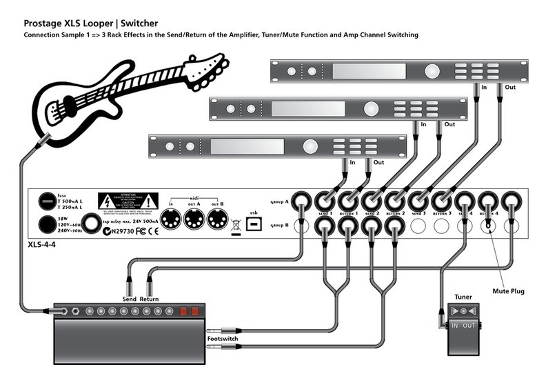
For example, you can use group A before the ampli er and group B in the Send/Return of your ampli er. Group
A and B are completely independent. This means that there is no ground connection between group A and
group B.
Basically, your guitar is connected to the “In”, and the “Out” is connected to the ampli er. The “Send” of the XDS
is connected to your effect Input, the related “Return” is connected to your effect Out.
If you like to use all eight loops in series, connect “Out A” with “In B” using a short Jack-Jack cable.
3.3.2 Tuner / Mute Function
Y
ou can use one loop as a Mute / Tuner function:
You can use one loop as a Mute / Tuner function:Y
- Connect the Input of your tuner to the “Send” (the Output of the tuner will not be connected).
- Plug a short-circuited Jack-plug into the “Return” (Tip connected with shield).
M
ute plug
3.3.3 Stereo
If
you own a XLS-8 or XDS-8, you can use it as a four-loops stereo system. Group A is your left channel, group B
the right channel. In order to link the two groups, you have to assign the same “Foot Controller Switch” to relay 1
of Group A as to relay 1 of group B, and so on... (see chapter 6.4).
If you like to use up to six loops in mono and only the last effect in stereo, there is a custom solution. Please
contact Prostage for more information.

3.4 Foot Controller
The foot controller(s) do not need a power adaptor. They are powered via the StageWire connection.
3.4.1 Connecting an Expression Pedal to the Foot Controller
Y
ou can connect one or two expression pedals to the jack socket of the foot controller. If you like to use two
You can connect one or two expression pedals to the jack socket of the foot controller. If you like to use two Y
expression pedals, you will need a Y-cable. The potentiometer of expression pedal no. 1 is located between tip and
shield. The Potentiometer of expression pedal no. 2 lies between ring and shield. Customized cables are available
at Prostage. You can also connect a switch, to use it as “Tap” for example, instead of an expression pedal.
Also a volume pedal can be used as an expression pedal. In this case, you have to connect the output of the
volume pedal to the foot controller. You will get the best resolution if you use a pedal with a 10k ohm or a 20k
ohm potentiometer.
One Expression Pedal:
Two Expression Pedals (Y-Cable):
Pedal 1
Pedal 2
Pedal 1
Expression Pedal with Switch (e.g. to control the Remote WahWah):
Switch
Pedal
=> The switch is connected as “Expression Pedal 2”. Hence, the Control Change assignment for the switch is set
under “CC No. Exp. Pedal 2” (See chapter 6.6.5).
IMPORTANT =>
In order to use the expression pedal(s), you have to calibrate them rst. You have to repeat the
following process each time you connect a different expression pedal:
3.4.2 Calibration of the Expression Pedal
Calibration of Expression Pedal No.1
(connected to Tip):
-
Pr
ess the two outer switches in the upper row (X05 => up & 4/9; X07 => 4 & 7; X10 => up & 9) for approx. three
seconds, until the three lower LEDs light up (X07) or a “0” is blinking (X05/X10). You are now in the calibration
mode.
-
Move the expression pedal to the position (dead stop) where you like to have the MIDI value 0.
-
Press the left switch in the lower row (X05 / X10 => down; X07 => 1). Pressing any other switch will abort the
calibration process.
-
Now the four upper LEDs light up (X07) or “127” is blinking (X05/X10) .
-
Move the expression pedal to the other dead stop, which is the position where you like to have the MIDI value 127.
-
Press the left switch in the lower row again.
If
you run a Firmware version below 1.20, the calibration is nished now. The foot controller returns to the normal
operation mode automatically.
If you run Firmware version 1.20 or later, the display will now show “63” (X05 / X10) or LED 2,5,6 lights up (X07).
This means, you can now calibrate the center position of your expression pedal. This way, you can generate a
logarithmic feel of the pedal:
-
Move the expression pedal to the position where you like to have MIDI value 63.
-
Press the left switch in the lower row again. The calibration is now nished.
=>
If you do not want to calibrate a center position, just abort calibrating by pressing any other switch. In this case,
the expression pedal will be calibrated linear.
The center position must differ at least 10” from 0 and 10” from 127 position. Otherwise, the center calibration
will be ignored and the expression pedal will be linear.
Calibration of Expression Pedal No.2
(connected to Ring):
B
asically, this works like the calibration of pedal No. 1, but you have to press the following switches for approx.
three seconds to enter the calibration mode:
-
Press the left and the second switch from the right in the upper row (X05 => up & 3/8; X07 => 4 & 6; X10 =>
up & 8)
Page
7

IN
OUT
LOOP 1
LOOP 2
LOOP 3
LOOP 4
Group A
IN
OUT
LOOP 1
LOOP 2
LOOP 3
LOOP 4
Group B
PSU
Page
8
4. Hum
Hum is a very broad issue. We will add more information on it as soon as possible. If you are having hum problems,
please contact us. We will be glad to help you.
The XDS is equipped with a ground lift switch. Try the position in which the noise is weakest.
Preventing Ground-Loops
Through
the Power Supply
Only if you have connected the “Out” of group A directly to the “In” of group B (using a short Jack cable),
you can
use the same power supply for the stompboxes in group A as for those in group B
. Otherwise, DO NOT use the
same power supply. In this case, the stompboxes in group A and group B must be powered independently.

IN
OUT
LOOP 1
LOOP 2
LOOP 3
LOOP 4
Group A
IN
OUT
LOOP 1
LOOP 2
LOOP 3
LOOP 4
Group B
PSU
send | returnsend | return
IN
OUT
LOOP 1
LOOP 2
LOOP 3
LOOP 4
Group A
IN
OUT
LOOP 1
LOOP 2
LOOP 3
LOOP 4
Group B
PSU
send | return
send | return
Page
9

Page
10
5.0 Using Your System
5.0 Using Your System
This chapter covers how to operate the unit. However, there is a lot more you can con gure with the Prostage
System Manager software (see chapter 6).
5.1 The Foot Controllers
D
epending on it’s settings, the foot controller sends “Program Change” and/or “On/Off Switches” commands to
the XTMpro and all MIDI units connected to the XTMpro. Please see chapter 6.6 for more information about the
settings and the possibilities of your foot controller.
IMPORTANT =>
Unlike conventional MIDI foot controllers, the PurpleLine foot controllers also receive MIDI
commands via the StageWire connection. For example: If you have connected two foot controllers and have set
them to the same MIDI channel or to Omni, they will stay synchronous all the time.
If you are using a X07 in operation mode “On/Off Switches”, then the LEDs on the X07 will stay synchronous with
the switches of your XTMpro all the time even if you switch it directly on the XTMpro. Therefore, the MIDI channel
of the foot controller has to be set to the same channel as “Relays => Receive on MIDI CH” (see chapter 6.4).
5.2 The XTMpro
(with Relay Option)
Y
ou can switch the relays by simply pushing the buttons on the front panel.
You can switch the relays by simply pushing the buttons on the front panel.Y
You can store up to 128 presets in your XTMpro. To do so, select a preset number on your foot controller. Then
enable/disable the switches at the XTMpro as you wish them to be for this preset. Press the “Store” button twice.
The red power LED will turn off for a short moment to indicate that the new preset is stored. All other programming
is made by the Prostage System Manager software (see chapter 6).
5.3 The XDS and XLS Loop System
X
DS and XLS are true-bypass loop systems. This means that the signal is going directly from the In to the Out if no
loop is on. The effects connected to the Send/Returns of the XDS/XLS are only in the signal path if the loop is on.
Therefore, the stompboxes have to remain switched on all the time.
The loop systems are equipped with a Soft X-Fade feature. This feature suppresses the audible click, which relays
can cause, and it makes preset changes sound more natural. You can turn off this feature if you wish (see Chapter
6.2.5). Due to this feature, there will be a resistance between Input and Output if your unit is not powered. It can
be bypassed with a simple hardware modi cation (jumpers). Ask Prostage (info@prostage.eu) for details.

Page
11
6. The Prostage System Manager Software
6. The Prostage System Manager Software
On the XTMpro itself, you can only store presets for the relays. All other settings are made with the Prostage
System Manager software (formerly known as “XTMpro Con guration Software”). It is available for Mac and PC.
Please download the latest version as well as the USB driver from our website:
www.prostage.eu => Downloads => Software & Driver
M
ake sure that the System Manager and the Firmware of the XTMpro / foot controller have the same version num-
ber. Otherwise, there may be features in the System Manager which are not supported by the unit itself (or vice-
versa). The last digit can be ignored: E.g. XTMpro Firmware Version 1.22 is compatible with the System Manager
1.20, but not with System Manager 1.30.
NO
TE => Remember that the XDS and XLS use same brain as the XTMpro. Thus, if we are talking about
XTMpro in the System Manager, this includes XDS or XLS
.
6.1 Installing the System Manager Software
(Mac & PC)
-
U
nzip the downloaded le.
-
Move the folder “Prostage System Manager xxx” into your local application folder. (DO NOT move any les inside
the folder to other locations).
6.1.1 Installing the USB Driver on Mac OSX
-
D
ouble click the downloaded le (.dmg) and follow the on-screen instructions.
6.1.2 Installing the USB driver on Windows
-
U
nzip the downloaded le.
-
When you connect the XTMpro for the rst time, the assistant will ask you for a driver =>
Here, you have to select the path where you unzipped/stored the folder with the USB Driver before.
NOTE =>
The USB Driver may install and appear as “FTDI Driver”.
6.1.3 Running the System Manager
M
ake sure that the XTMpro is properly connected with your computer via USB.
IMPORTANT => The System Manager is an of ine tool. This means that you have to read out the
XTMpro after launching the System Manager in order that it shows the current settings in your
XTMpro.
This happens automatically when you launch the software given that the XTMpro is properly connected
with the computer. Otherwise, you have to read out the XTMpro manually: “File” => “Read XTMpro”.
If you are working with two or more XTMpro’s, you have to read out the settings each time you plug the USB cable
into a different device. Otherwise, you will mix the settings of the different devices.
IMPORTANT => Changes made in the System Manager have to be con rmed with “Update XTMpro”.
This will send all settings of the “Program Mapping”, “Relay”, “Switch Assignment” and “XTMpro Basic Settings”
tab to the XTMpro. “Foot Controller Settings” and “Remote WahWah” are not stored in the XTMpro but in the
foot controller or the Remote WahWah respectively. If you make any changes in one of the two tabs, you have to
con rm them with the button “Update Foot Controller” or “Update Wah Wah” / “Store Preset” respectively.
You can also save and open presets to / from your local hard disk (“File” Menu).
NOTE =>
The preset-names, as well as the description of the eight Program Mapping banks and the eight Relays
are only saved to your hard disk; they are not stored in the XTMpro. Thus, we recommend to save your settings to
the hard disk as well.
6.1.4 The File Menu
Open
Con guration
loads a previously saved setup into the System Manager (Filename extension: .pcf)
Save
Con guration (as)
saves the XTMpro con guration to your local hard disk. This includes all the settings
from the “Program Mapping”, “Relays”, “Switch Assignment” and “XTMpro Basic Settings” tabs, as well as the
“Foot Controller” default settings.
Read XTMpro
loads the settings stored in the connected XTMpro into the System Manager.
Update XTMpro
sends the current settings from the System Manager to the XTMpro.
Reset
restores the factory defaults for different sections inside the System Manager.
Open WahWah Presets
loads the presets for the Remote WahWah (see the Remote Wah’s users manual)
Save WahWah Presets (as)
saves the presets for the Remote WahWah (see the Remote Wah’s users manual)
Page Setup
allows you to adjust the paper size for printing the patch list
Print Patch List
prints the entire “Program Mapping” table.
Quit
closes the Software.

MIDI In
Page
12
6.2 The “XTMpro Basic Settings” Tab
6.2.1
General Settings / Foot Controller
This setting only concerns the inscription within the System Manager. For example, if you select X07, the Switches
will be labeled 1,2,3,4,5,6,7. If you select X01, the switches will be labeled A,B,C,D. This setting does not affect the
functionality of your system. However, inside the software only the switches will be available which also exist on
the foot controller. If you want to make all the switches available, you have to set it to “other”.
6.2.2 MIDI In
Fo
rward to
Here
you choose which Out’s the data from MIDI In is routed to.
Process Data
Yo
u can select if Program Changes and/or Control Change messages received at the MIDI In shall be processed by
the “Program Mapping” tab and if they should be used to switch the relays.
NOTE =>
Data received at the StageWire will always be processed by the Program Mapping and will be used to
switch relays. Data received on MIDI In will only be processed by Program Mapping and will be used to switch
relays if the corresponding check box is enabled. If the “Program Mapping” tab is disabled or the MIDI channel
does not match, Program Changes will be sent to MIDI Out A/B based on the “Forward to” and “MIDI Thru Filter”
settings.

Page
13
MIDI In
(e.g. CC No. 22)

Page
14
6.2.3 MIDI Thru Filter
You can lter the different types of MIDI data at the MIDI Out A and B. For example, you can set Out A to send
Program Change only. This can make sense if you connect a tube ampli er with a MIDI interface which only
accepts Program Changes.
IMPORTANT =>
The MIDI Thru lter only affects data sent directly from the StageWire or MIDI In to the MIDI
Out(s). MIDI data mapped or generated in the “Program Mapping” and “Switches Assignment” tab will always be
sent to the MIDI Out(s) assigned in the tab, regardless of the MIDI Thru lter settings.
This means for example, if you setup a “Program Mapping”, which sends Program Change to Out A, but the
check box “MIDI Thru Filter” / “MIDI Out A” / “Send Program Change” is disabled, the Program Changes from this
“Program Mapping” are sent nevertheless.
6.2.4 Tap Function
Tap
allows you to adjust tempo-based parameters like delay time by rhythmic tapping onto the Tap switch of your
foot controller (see 6.6.3). The Tap command is sent to your effect unit either analogously using the Tap relay
connector of the XTMpro or digitally by a MIDI command.
Tap Relay | Receive as MIDI
Yo
u can choose if the tap relays should work as a momentary switch or as a latching switch:
“momentary” =>
When you press the Tap switch on your foot controller, the Tap relays will switch on. When you
release the switch, the relays will switch off (like a a doorbell switch).
“latching” =>
When you press the Tap-switch on your foot controller for the rst time, the relay will switch on.
When you press it a second time, the relay will switch off, and so on (like a light switch).
The correct setting for this depends on how the connected unit works. Try it out!
Fu
rther, the Tap relays can also be switched by a MIDI Control Change command. To do so, select a Control
Change number and MIDI channel next to “Receive as MIDI”. If you do not want the relay to be switched by any
CC command, set “CC No.” to “Disabled”.
Send as MIDI
The Ta
p command from the StageWire input can also be sent as a MIDI-CC command or even be used for System
Realtime messages (start/stop). Select a CC number, a MIDI channel, and enable one or both MIDI Outs. Tap switch
“On” will be sent as value 127, Tap switch “Off” will be sent as value 0. You can also choose to send a momentary
command, or a latching command:
“momentary” =>
When you press the “Tap” switch on your foot controller(s), the chosen CC command with
value 127 will be sent. When you release the switch, the CC command with value 0 will be sent.
“latching” =>
When you press the “Tap” switch on your foot controller for the rst time, the CC command with
value 127 will be sent. When you press it for the second time, the CC command with value 0 will be sent.
6.2.5 Relays Option
N
OTE =>
If you use an XTMpro without relay option, these settings are not available. “Group B” is only available
if you are using an XDS or XLS system with both groups equipped.

Page
15
Group A / Group B
Sel
ect if the relays of the group should work independently, or if you like to make some radio-button groups
(channels). Radio buttons means that within the linked relays only one can be “on” at the same time. For example,
if you choose ”3 channels + 1 independent switch”, it works as follows:
Assumed switch 1 is on at the moment, now press switch 2. This will automatically turn off switch 1. Then you
press switch 3. Switch 2 will be turned off. This makes sense if you want to switch channels of your guitar ampli er.
Switch 4 will work independently from the other switches in this example. This makes sense for a boost function
or a reverb.
If “Allow off” is enabled, the active radio button can be switched off. In that case, none of the buttons in this
group would be on. This could be useful when switching channels in an ampli er which can be muted when no
channel is active.
If you have an eight-channels system, you can also link the radio buttons of relays group 1+2 by enabling “Link
channels of Group A and Group B”.
Soft X-Fade
Th
is feature only affects the audio-loops. It has no effect on switching relays. You can enable or disable the Soft
X-Fade feature for Group A and B independently. Soft X-Fade is a very short fade out / fade in at the Output of the
group which suppresses the click that relays can cause. It also makes the preset change sound softer. If you have
connected eight stompboxes in series, enable the Soft X-Fade feature only on group B.
Send Control Changes to MIDI Out Using CC from Switch Assignment
W
hen Pushing Button at XTMpro
By default, the switches of your XTMpro only control the relays. If you also like to send MIDI commands when
you press this buttons, enable the check box “When Pushing Button at XTMpro”. This will send the CC commands
de ned in the “Switch Assignment” tab. (see 6.5).
When Recalling Presets
If you like to send the new on/off state of the relays after receiving a Program Change, enable the check box
“When Recalling Presets”. Each relay which has changed its on/off state will send a Control Change command
based on the settings in the “Switch Assignment” tab (see 6.5).
IM
PORTANT =>
These CC commands will also be sent if the “Switch Assignment” page is disabled. If you like to
modify some CC settings inside the disabled page, enable it temporarily to make the settings, and disable it when
you are done. See 6.5 for more information.
Program Change on
StageWire or MIDI In
Relays have been
switched by
Preset Recall
Relay is
switched
manually

Page
16
6.3 The “Program Mapping” Tab
“Program Mapping” allows you to make MIDI mappings for up to eight different units. The table can manage up
to 128 MIDI presets. If you disable the complete “Program Mapping” tab or if the MIDI channel of the received
Program Change does not match the setting of “Receive PC on MIDI CH”, then the MIDI command will be sent to
the MIDI Outs based on the settings in the “XTMpro Basic Settings” tab. (see 6.2).
You can print this table: “File” => “Print Patch List”
Controlled Unit | Preset Name
Y
ou can label each controlled unit with a meaningful name. You can also name each of the 128 presets. The names
You can label each controlled unit with a meaningful name. You can also name each of the 128 presets. The names Y
will not be stored in the XTMpro, but they will be stored if you save the settings to the hard disk.
6
.3.1 Basic Settings of the “Program Mapping” Table
Receive PC on MIDI CH
The “Program Mapping” tab only listens to Program Changes with corresponding MIDI channel. All Program
Changes on other channels will be sent to the MIDI Out’s according to the settings in the “XTMpro Basic Settings”
tab. “Omni” means that all 16 MIDI channels are accepted.
P
age
Th
e table shows only ten of the 128 presets. Use the “Page” pull-down menu to ip through all preset numbers.
Sh
ow
Th
ere are MIDI devices that work with preset numbers 0-127. Others work with 1-128. Therefore, there may be
an offset of 1 between different devices. The setting “Show” helps you to avoid this. If the lowest number of your
foot controller is “0”, choose show “0-127”. If the lowest number of your foot controller is “1”, choose “1-128”.
This way, you avoid an offset of 1.
You can also do this for each of the eight banks. Depending on how the controlled unit works, set it to “0-127”
or “1-128”.

5
Page
17
6.3.2 De ning Mappings
Ea
ch of the eight mappings can be disabled or you choose one of three different mapping modes.
Each mapping has its own transmit settings:
Send on MIDI CH
Ch
ooses the MIDI transmit channel for the commands of this mapping. NOTE => If you use several “Program
Change” mappings, they have to use different MIDI channels. You cannot send several Program Changes on the
same MIDI channel simultaneously. Different MIDI devices have to use different MIDI channels in order to control
them independently.
To Out A / Out B
S
elect which MIDI Out(s) the commands should be sent to. If you are in mapping mode “Control Change”, the
MIDI commands can be sent to the foot controller (XLR) as well as to MIDI Out A and B.
0-127 / 1-128
If
the controlled unit’s preset numbering starts with 0, choose “0-127” here. If the unit’s lowest preset number is
1, choose “1-128”. Doing so, you will prevent an offset of 1.
6.3.3 Mapping Mode “Program Number”
Thi
s allows you to make Program Change mappings. This means, that you can recall a different, individual preset
number for each connected device by just pressing one switch on the foot controller.
In the example above, the following happens when you select preset no. 5 on your foot controller:
First, the XTMpro checks if the “Program Mapping” is enabled and if the MIDI channel of the foot controller
matches the “Receive PC on MIDI CH” setting. If one of these conditions is not given, the Program Change is
forwarded to MIDI Out A/B according to the “XTMpro Basic Settings”.

5
5
Page
18
If both conditions are true, the following program changes will be sent:
Preset no. 3 to Amp (e.g. Lead Channel); Preset no. 99 to Axe FX (e.g. Mute); Preset no. 0 to Remote WahWah
(Bypass)
If
you, for example, select preset no. 8 at your foot controller, the following presets will be sent:
Preset no. 2 to Amp (e.g. Rhythm Channel); Preset no. 7 to Axe FX (e.g. Harmonizer); Preset no. 0 to the Remote
WahWah (Bypass)
NOTE =>
If the box is empty, no preset number will be sent at all.
6.3.4 Mapping Mode “Control Change”
Yo
u can also send Control Change messages instead of Program Changes.
For example, you have connected a TC G-Major to the XTMpro, but you like to work with the same preset all the
time and only turn on/off the effects (e.g. Delay, Reverb, Flanger, Compressor), as you would use stompboxes. You
can do so by sending CC commands. Besides the controller number, you also have to send a controller value. Value
0 means “off”, value 127 means “on”. Of course the TC G-Major also has to be programmed properly in order to
work this way.
In the sample above, Control Change 82 with value 127 (= Chorus On) is sent to the G-Major when you recall
preset no. 2. If you recall any other preset, the chorus is turned off (Control Change 82 with value 0).
If you recall preset no. 9 in the example above, the frequency of your Remote WahWah will be set to approximately
1,1kHz (CC 93 = Wah frequency, value 80 = 375-1124 Hz). This will result in a lower WahWah effect than the
standard WahWah. If you recall any other preset, no Control Change will be sent to the Wah because the box
“No.” is empty.

5
Page
19
6.3.5 Mapping Mode “Convert incoming CC”
Be
side Program Change commands, you can also map Control Change (CC) commands. Example:
You have connected an expression pedal to your foot controller which sends CC Nr. 7 (Volume).
In preset no. 9 you like to use the expression pedal to control the Contour Boost frequency of the Remote WahWah
instead of the normal WahWah effect. Therefore, you set the CC no. to 94 (this is the Contour Boost frequency of
the Remote WahWah).
In preset no. 7, you like to control the normal Wah effect of your Remote WahWah. Thus, you send CC no. 7 (this
means that the same command is sent as received).
If you select any other preset than 7 or 9, your expression pedal is inactive because the “No.” eld is empty
(incoming Control Change commands will be ltered / muted).
NOTE =>
Incoming Control Change commands that are not subject to convert in any of the eight banks will be
sent to MIDI Out A/B according to the “XTMpro Basic Settings” (see 6.2). In our sample, this means that only CC
no. 7 on MIDI channel 1 is processed by the “Program Mapping” tab. All other CC commands received by the
XTMpro will be sent via MIDI Out A/B (depending on the basic settings) without any modi cation of the data.
Fu
rther, you can scale and invert the values of the Control Changes. This means that you can invert the direction
of your expression pedal and scale it, for example, to affect only 50% of the effect when moving 100” of the
expression pedal. To access this additional settings, click the “Scale” check box.
In this sample, the resolution of the Control Change value is scaled to 50%. This means that, instead of 128 possible
values, only 64 values will be sent. Because lowest value is set to 31, the values received from the expression pedal
(0-127) will be forwarded to the Remote WahWah as 31 to 95. In this example, the expression pedal only controls
the middle frequencies of the Contour Boost, while not reaching its very low and very high frequencies.
Fu
rther, the direction of the expression pedal is inverted. Instead of “Expression pedal value 0” = “WahWah Value
31” and “Expression pedal value 127” = “WahWah Value 95”, it works like:
“Expression pedal value 0” = “WahWah Value 95” and “Expression pedal value 127” = “WahWah Value 31”
Yo
u can also use this feature if you want to use the same switch on your X07 (or X10 in 5+5 operation mode) for
different things, depending on the selected preset. (In the “Switch Assignment” tab, the output of the switch has
to be set to “use Program Mapping”).
For example, you use switch 5 to turn on/off the Distortion in the Fractal Audio AxeFX. But on one special preset,
you want to start the looper instead. Therefore, convert the incoming CC to send a different command to the
AxeFx in this speci c preset. Of course, you have to program the AxeFx accordingly.
Table of contents
Other Prostage Switch manuals
Popular Switch manuals by other brands
Enterasys
Enterasys Matrix 7G4202-72 Hardware installation guide
StarTech.com
StarTech.com SV231DPU2 instruction manual
TLS Electronics
TLS Electronics 875450 user manual
Eaton
Eaton CUTTLER-HAMMER Arcflash Reduction Maintenance... Application and Installation

Broadcast Pix
Broadcast Pix BPswitch Operator's manual

HP
HP J4091A Installation and reference guide
