PROTEOR 5G50 Instruction sheet

5G5099-05/07 P1/12
FOUR 5G50
NOTICE DE MISE EN SERVICE ET D’UTILISATION (P2-5)
OVEN 5G50
INSTRUCTIONS FOR FIRST START AND USE (P6-9)
Servi e ommer ial / Customers servi e
- téléphone : +33 (0)3 80 78 42 10
- télécopie : +33 (0)3 80 78 42 15
- e-mail : ht.o thopedie@p oteo .com
- ad esse : PROTEOR HANDICAP TECHNOLOGIE
Se vice O thopédie
6, ue de la Redoute
Z.I. Saint-Apollinai e
B.P. 37833 - 21078 DIJON Cedex - F ance
www.p oteo .com

NOTICE DE MISE EN SERVICE ET D’UTILISATION du FOUR 5 G 50
1 - IMPLANTATION
Au moment de son installation, un écart minimum de 10 centimètres est à respecter à
l’arrière du four s’il est positionné contre un mur, pour permettre l’aération.
2 - CARACTERISTIQUES TECHNIQUES
Encombrement : P. 950 H. 1550 L. 1380 mm
Sauf de ande spécifique, tous les fours sont livrés pour une ali entation
400V triphasé.
Deux tensions sont proposées (voir chapitre 1ère mise en route) :
400 Volts triphasé.
230 Volts triphasé.
PUISSANCE : 4.5 KW
Régulateur digital basse tension.
Température d’utilisation : de 0°C (32°F) à 250°C (482°F)
Ce four est destiné à ramollir des matières plastiques pour des opérations de
thermoformage (PP, PE, EVA).
3 INSTALLATION
3-1 Ali entation électrique :
Le four doit être raccordé par un électricien ou par une personne compétente.
ATTENTION :
Deux tensions d’ali entation sont proposées (230V triphasé ou 400V triphasé).
Avant tout branche ent électrique, vérifier que la position du co utateur 230-400V
correspond à la tension disponible au réseau. Une erreur de co utation
endo agerait le four.
Si le commutateur est dans la position 400V et que la ligne électrique de l’utilisateur est
bien en 400V tri : il n’y a rien à modifier.
Si par contre la ligne électrique à disposition délivre 230V tri (s’en assurer en mesurant la
valeur ou en la faisant vérifier par un électricien) : il faut alors commuter le sélecteur de
tension situé en haut à gauche dans le coffret électrique.
Pour réaliser cette commutation, il y a lieu de :
•
Prendre la manette qui se trouve dans le sachet d’accessoires au fond du coffret.
•
Introduire l’a e de la manette dans le commutateur (attention à l’orientation des
cannelures)
•
Tourner la manette vers la gauche (voir l’étiquette située sur le commutateur) sur
230V.
•
Retirer la manette et la replacer dans le sachet au fond du coffret.
•
E traire les 3 cartouches fusibles repérées 8A et les remplacer par 3 cartouches
fusibles 12A.
(Ces cartouches de rechange sont situées dans le sachet au fond du coffret ; y ranger les
cartouches 8A inutilisées.)
Cette commutation étant réalisée, on peut désormais mettre la ligne d’alimentation sous
tension et passer au fonctionnement du four.
5G5099-05/07 P2/12

3-2 Sole : 1er mise en servi e et entretien
La sole est en du alumin enfo cée pa des t ave ses en inox.
Recouv i la sole avec la feuille de Téflon éfé ence FNX070.
Nettoye la feuille éguliè ement avec de l’eau savonneuse et la change si besoin.
4 FONCTIONNEMENT
1. Mettre la ligne d’alimentation sous tension.
2. Tourner le sectionneur général sur « 1 ». Le voyant blanc s’allume.
3. Actionner le bouton « marche-arrêt ». Le voyant « jaune » (chauffage) s’allume.
Les lampes intérieures du four s’allument aussi.
5 REGLAGE DE LA TEMPERATURE DU FOUR ET ETALONNAGE
Pour afficher la température désirée sur le régulateur, procéder de la façon suivante :
1. Simultanément, appuyer sur le bouton rouge et tourner le bouton noir pour afficher la
température désirée.
2. Relâcher le poussoir rouge.
Le matériel est étalonné par des essais après fabrication. Cet étalonnage consiste à faire
coïncider les indications du régulateur avec la température réelle du four.
Ce point peut être vérifié:
Placer un thermomètre à l’intérieur du four.
Mettre en température.
Si les indications données par les deu appareils de mesure sont différentes, agir sur la
vis « digits » (accessible à l’arrière du régulateur) afin de les faire coïncider.
6 ARRET DU FOUR
Couper le bouton « marche-arrêt ». Le voyant jaune s’éteint.
7 MISE HORS TENSION DU FOUR
1. Couper le sectionneur général. Le voyant blanc s’éteint : position 0
2. Débrancher éventuellement.
5G5099-05/07 P3/12

8 FUSIBLES
Un jeu de fusibles de rechange est fourni avec votre four.
9 SECURITE
L’utilisation du four doit être réservée e clusivement au ré-
chauffage des produits pour lesquels il a été initialement
conçu.
Ne JAMAIS échauffe de p oduits à destination alimentai e.
Présence de tension dans l’armoire électrique.
Avant chaque intervention électrique, positionner le
sélecteur sur 0.
Risque de brûlure important ; la vitre de la porte peut
atteindre plus de 200 °C (392°F).
N’utiliser qu’une sole à la fois.
5G5099-05/07 P4/12

DEPANNAGES SUR FOUR 5G50
PANNES
VERIFICATIONS CONSIGNES
D’INTERVENTIONS
Le four reste hors tension.
Aucun voyant n’est allumé, ni
le régulateur.
• Vérifier la fiche d’alimentation.
• S’assurer de la présence de
tension dans la ligne d’alimenta-
tion du four.
• Reprendre point par point le
chapitre «FONCTIONNEMENT»
de la notice.
• Tester les fusibles F1, F2 et F3
de puissance et les fusibles F4,
F5, F6, F7 et F8 de commande.
• Prévenir le SAV PROTEOR
pour diagnostic.
Le régulateur est activé mais
le four ne chauffe pas ou il
est trop long pour atteindre la
température de consigne.
• Tester les fusibles F1, F2, F3.
• Régler le thermostat à tempéra-
ture.
• S’assurer que le thermostat de
sécurité est réglé à 250°C (dans
l’armoire électrique)
• Si le problème persiste, préve-
nir le SAV PROTEOR
La température affichée au
régulateur est inférieure à la
consigne.
• Tester KM1, vérifier la présence
de tension en sortie
• Mettre le four hors tension et
vérifier avec un ohmmètre les
valeurs obtenues en sortie de
KM1.
Elles doivent être identiques.
• Chercher la ou les résistances
et/ou connectiques défaillantes.
Sur le régulateur :
• L’affichage est erroné et
instable.
• Remplacement du régulateur et
de la sonde.
• Prévenir le SAV PROTEOR
pour remplacement du matériel.
• L’affichage indique «EEE»
• Vérifier le bon raccordement des
connectiques de la sonde sur le
régulateur.
• Suivre le chapitre «réglages de
la température et étalonnage»
dans la notice.
• L’affichage indique «- - -»
• Sonde hors service.
• Sonde à remplacer.
ATTENTION :
Ces consignes de dépannages sont à réaliser avec l’accord du Service Après-Ventes
PROTEOR
5G5099-05/07 P5/12

5 G 50 OVEN : INSTRUCTIONS FOR FIRST START AND USE
1 LOCATION
In case of installation near a wall, take care to place the oven at least 10 cm far from this
wall, for aeration purpose.
2 TECHNICAL FEATURES
Overall dimensions : D. 950 H. 1550 W. 1380 mm
Unless otherwise specified, each oven is provided for 400 V three phase supply.
2 voltages are convenient (please see chapter ‘’first start’’) :
either 400 V three phase.
or 230 V three phase.
Power : 4.5 KW
Low voltage digital regulator.
Working temperature : from 0°C (32°F) to 250°C (482°F)
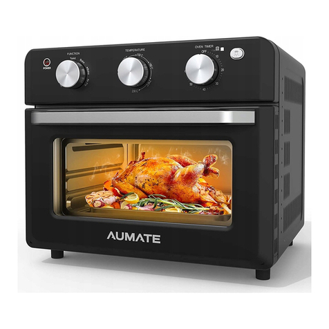
This oven is aimed at softening plastic materials for thermoforming (PP, PE, EVA,…).
3 INSTALLATION
3.1 - Electrical power supply :
The oven must be connected by an electrician or a competent worker.
CAUTION :
Two voltages are convenient (either 230V three phase or 400V three phase).
Before any electrical connection, check that the 230-400 V switch is turned on the
available voltage. A wrong switch position would da age the oven.
If the switch is turned on 400V for a user’s electrical power line of 400 V three phase : do
not modify anything.
In the case of a user’s electrical power line of 230 V three phase (check it by measuring the
voltage or have it checked by an electrician) : change over the voltage selector located
above on the left in the electrical cabinet.
For this change over, proceed as follows :
•
Take the handle that is in the package of accessories at the bottom of the electrical
cabinet.
•
Insert the handle a is into the switch (take care to the flute orientation)
•
Turn the handle on the left on 230V (See the label located on the switch).
•
Remove the handle and put it again in the package of accessories at the bottom of the
electric cabinet.
•
Remove the 3 fuse cartridges marked 8A and replace them by 3 fuse cartridges 12A.
(Take these fuse cartridges out of the package at the bottom of the electrical cabinet and
put there the unused 8A cartridges).
After this change over you can connect the electric power line and start the oven.
5G5099-05/07 P6/12

3-2 Plate : First start and maintenan e
The plate is made of du aluminium and einfo ced with inox c oss ba s.
Cove the plate with a teflon sheet FNX070.
Wash the plate egula ly with soapy wate and eplace it if necessa y.
4 OPERATING
1. Connect the power supply line
2. Turn the disconnecting switch on “1”. A white indicator light glows.
3. Turn on the “ON - OFF” button. The yellow indicator light (heating) glows. The interior
lightings of the oven glow too.
5 OVEN TEMPERATURE ADJUSTMENT AND GAUGING
Proceed as follows to display the required te perature on the regulator :
1. Simultaneously press the red button and turn the black one to display the required
temperature.
2. Release the red push button.
The equipment is gauged during tests after its manufacturing. This gauging makes the
regulator indications match the real oven temperature.
It is possible to check this gauging.
In this case, put a thermometer into the oven.
- Warm up the oven.
- If the two measurement devices do not show the same indications, act on screw
«digits» (at the back of the regulator) to have them match each other.
6 OVEN STOP
Turn off the «ON - OFF» button. The yellow indicator light goes out.
7 DISCONNECTING THE OVEN
1. Turn off the disconnecting switch. The white indicator light goes out : position 0.
2. Unplug if you want.
5G5099-05/07 P7/12

8 FUSES
The oven comes with a set of fuses for replacement.
9 SAFETY
This oven must be used only to heat the products for which it
has been initially designed.
NEVER use it to re-heat food.
Voltage in the electrical cabinet.
Before each action on the electrical system, position the dis-
connecting switch on 0.
Important burn hazard ; the door window can reach more
than 200 °C (392°F).
Use only one plate at the same time.
5G5099-05/07 P8/12

REPAIRS OF THE OVEN 5G50
BREAKDOWNS CHECKS OPERATING INSTRUCTIONS
The oven remains powered off.
The indicator lights and the regu-
lator do not glow.
• Check the supply plug.
• Check the presence of volt-
age in the power supply line
of the oven.
• Read step by step the chapter
‘’OPERATING’’ of the instructions
for use.
• Test the F1, F2 and F3
power fuses and the F4, F5,
F6, F7, F8 control fuses.
• Inform PROTEOR’s after sales
service for diagnosis.
The regulator operates but the
oven does not heat or it takes
too much time to achieve the
recommended temperature.
• Test the F1, F2 and F3
fuses.
• Adjust the temperature
thermostat.
• Be sure that the safety
thermostat is set at 250°C
(in the electrical cabinet).
• If the problem remains after
checking, inform PROTEOR’s
after sales service.
The temperature displayed on
the regulator is lower than the
recommended one.
• Test KM1. Check the pres-
ence of voltage at its end.
• Disconnect the oven and
check with an ohmmeter the
values of KM1outputs. They
must be identical.
• Look for the defective resis-
tance(s) and/or the defective
connections.
On the regulator :
• The display is wrong and unsta-
ble
• Change the regulator and
the probe.
• Inform PROTEOR’s after sales
service for material replacement.
• The display indicates ‘’EEE’’
• Check that the probe
is well connected to the
regulator.
• Read the chapter ‘’oven tem-
perature adjustment and gauging’’
in the instructions for use.
• The display indicates ‘’---‘’
• Inoperative probe.
• The probe must be changed.
CAUTION :
These repair instructions ust be carried out with the consent of PROTEOR’s after
sales service.
5G5099-05/07 P9/12

5G5099-05/07 P10/12

5G5099-05/07 P11/12

5G5099-05/07 P12/12
Table of contents
Languages: