Proware EP-2126-SA3 User manual

EP-2126-SA3
SCSI TO SATA II
RAID SUBSYSTEM
Installation and User Manual
Revision 1.0

2
Preface
About this manual
This manual provides information regarding the quick installation and hardware features
of the EP-2126-SA3 RAID subsystem. This document also describes how to use the
storage management software. Information contained in the manual has been reviewed
for accuracy, but not for product warranty because of the various
environment/OS/settings. Information and specifications will be changed without further
notice.
This manual uses section numbering for every topics being discussed for easy and
convenient way of finding information in accordance with the user’s needs. The following
icons are being used for some details and information to be considered in going through
with this manual:
Copyright
No part of this publication may be reproduced, stored in a retrieval system, or
transmitted in any form or by any means, electronic, mechanical, photocopying,
recording or otherwise, without the prior written consent.
Trademarks
All products and trade names used in this document are trademarks or registered
trademarks of their respective holders.
Changes
The material in this document is for information only and is subject to change without
notice.
IMPORTANT!
These are the important information that the user must remember.
WARNING!
These are the warnings that the user must follow to avoid
unnecessary errors and bodily injury during hardware and software
operation of the subsystem.
CAUTION:
These are the cautions that user must be aware to prevent damage
to the equipment and its components.
NOTES:
These are notes that contain useful information and tips that the
user must give attention to in going through with the subsystem
operation.

3
TABLE OF CONTENTS
Preface...................................................................................................................... 2
Before You Begin...................................................................................................... 5
Safety Guidelines ........................................................................................................5
Controller Configuration...............................................................................................5
Packaging, Shipment and Delivery ................................................................................5
Unpacking the Subsystem ........................................................................................6
1 Product Introduction........................................................................................... 7
1.1 Identifying Parts of the EP-2126-SA3.....................................................................8
1.1.1 Front View....................................................................................................8
1.1.2 Rear View ....................................................................................................8
1.1.3 Top View......................................................................................................8
1.2 Enclosure Chassis ................................................................................................9
1.3 Technical Specifications ...................................................................................9
1.3.1 RAID Features...............................................................................................9
1.3.2 Enclosure.................................................................................................... 10
1.3.3 Environmental............................................................................................. 10
2 Physical Components......................................................................................... 11
2.1 Controller Module .............................................................................................. 11
2.1.1 Controller Module Panel............................................................................... 11
2.1.2 Controller Module Installation....................................................................... 12
2.1.3 Controller Board Replacement...................................................................... 13
2.2 Power Supply / Fan Module ................................................................................ 14
2.2.1 PSFM Panel ................................................................................................ 14
2.2.2 Power Supply Module LED ........................................................................... 15
2.2.3 Power Supply Installation ............................................................................ 15
2.2.4 Fan Replacement ........................................................................................ 17
2.3 Drive Carrier Module.......................................................................................... 18
2.3.1 Disk Drive Status Indicators ......................................................................... 18
2.3.2 Lock Indicator............................................................................................. 19
2.3.3 Disk Drive Installation ................................................................................. 19
2.4 LCD Display Panel.............................................................................................. 21
2.4.1 LCD Display Panel LEDs............................................................................... 21
2.4.2 LCD Front Panel Function Keys ..................................................................... 22
2.5 Rackmount Slide Rail Installation ........................................................................ 23
3 Getting Started with the Subsystem................................................................. 27
3.1 Connecting the RAID Subsystem to the Host.......................................................... 27
4 Introduction ...................................................................................................... 28
4.1 RAID Concepts.................................................................................................. 28
4.2 SCSI Concepts .................................................................................................. 32
4.2.1 Multiple SCSI Format Support ...................................................................... 32
4.2.2 Host SCSI ID Selection ................................................................................ 33
4.2.3 Terminators................................................................................................ 33
4.3 Disk Drive Organization...................................................................................... 33
4.3.1 Physical Drive Groups.................................................................................. 33
4.3.2 Logical Unit Number (LUNs)......................................................................... 33
4.3.3 Hot-Swap Drive Replacement....................................................................... 34
4.3.4 Disk Failure Detection.................................................................................. 34
5 Configuration Utility Options............................................................................. 35
5.1 Configuring through a Terminal .......................................................................... 35
5.2 Configuring the Subsystem Using the LCD Panel .................................................. 38
6 Accessing the proRAID Manager GUI................................................................ 40
6.1 Installation........................................................................................................ 40
6.1.1 Installing on Windows System....................................................................... 40
6.1.2 Installing on Linux ...................................................................................... 43
6.2 Starting ProRAID Manager.................................................................................. 44

4
6.3 Configuration Procedures ................................................................................... 46
6.3.1 Change Password ....................................................................................... 46
6.3.2 Mount RAID Subsystem............................................................................... 46
6.3.3 Detach RAID Subsystem.............................................................................. 47
6.3.4 View proRAIDMgr Log ................................................................................. 47
6.3.5 Event Manager ........................................................................................... 48
7 RAID Management ............................................................................................ 50
7.1 About RAID....................................................................................................... 50
7.1.1 RAID Considerations ................................................................................... 50
7.2 Array Status...................................................................................................... 51
7.2.1 Array Properties.......................................................................................... 52
7.3 Creating a RAID ................................................................................................ 54
7.3.1 Configuring Array Options............................................................................ 54
7.3.2 Rebuilding an Array..................................................................................... 58
7.4 Parity Checking a RAID ...................................................................................... 59
7.5 Modifying RAID Settings..................................................................................... 59
7.5.1 Erase the RAID ........................................................................................... 60
7.5.2 Change Settings.......................................................................................... 60
7.5.3 Delete Volume ............................................................................................ 61
7.6 Selecting/Changing a Sparing disk ...................................................................... 61
8 Channel Management........................................................................................ 62
8.1 Multiple SCSI Format Support............................................................................. 62
8.2 Host SCSI ID Selection....................................................................................... 62
8.3 Configuring Channel Options .............................................................................. 62
9 System Monitoring ............................................................................................ 64
9.1 System Information ........................................................................................... 64
9.2 Slot List (Disk View)........................................................................................... 64
9.3 LUN Mapping Information .................................................................................. 65
9.4 Controller Log ................................................................................................... 65
9.5 Hardware Monitor.............................................................................................. 66
10 Administration Menu....................................................................................... 67
10.1 System Setting ................................................................................................ 67
10.2 NTP setting ..................................................................................................... 69
10.3 Mail Notification............................................................................................... 70
10.4 SNMP Settings................................................................................................. 71
10.5 Restart ........................................................................................................... 71
10.6 Set Faulty ....................................................................................................... 71
10.7 Updating Firmware .......................................................................................... 72
10.7.1 Upgrading Firmware through VT-100 Terminal Emulation ............................. 72
10.7.2 Upgrading Firmware through proRAID Management..................................... 74
APPENDIX............................................................................................................... 75
Menu Diagram .......................................................................................................... 75

5
Before You Begin
Before going through with this manual, you should read and focus to the following safety
guidelines. Notes about the subsystem’s controller configuration and the product
packaging and delivery are also included.
Safety Guidelines
To provide reasonable protection against any harm on the part of the user and to obtain
maximum performance, user is advised to be aware of the following safety guidelines
particularly in handling hardware components:
Upon receiving of the product:
Place the product in its proper location.
To avoid unnecessary dropping out, make sure that somebody is around for
immediate assistance.
It should be handled with care to avoid dropping that may cause damage to the
product. Always use the correct lifting procedures.
Upon installing of the product:
Ambient temperature is very important for the installation site. It must not exceed
30◦C. Due to seasonal climate changes; regulate the installation site temperature
making it not to exceed the allowed ambient temperature.
Before plugging-in any power cords, cables and connectors, make sure that the
power switches are turned off. Disconnect first any power connection if the power
supply module is being removed from the enclosure.
Outlets must be accessible to the equipment.
All external connections should be made using shielded cables and as much as
possible should not be performed by bare hand. Using anti-static hand gloves is
recommended.
In installing each component, secure all the mounting screws and locks. Make sure
that all screws are fully tightened. Follow correctly all the listed procedures in this
manual for reliable performance.
Controller Configuration
This RAID subsystem supports single controller configuration.
Packaging, Shipment and Delivery
Before removing the subsystem from the shipping carton, you should visually inspect
the physical condition of the shipping carton.
Unpack the subsystem and verify that the contents of the shipping carton are all
there and in good condition.
Exterior damage to the shipping carton may indicate that the contents of the carton
are damaged.
If any damage is found, do not remove the components; contact the dealer where
you purchased the subsystem for further instructions.

6
Unpacking the Subsystem
The package contains the following items:
• RAID subsystem unit
• Two power cords
• One external serial cable
• One external UPS cable
• One RJ-45 Ethernet cable
• Two external SCSI cables
• Two Active Terminators
• Installation Reference Guide
• Spare screws, etc.
If any of these items are missing or damaged, please contact your dealer or sales
representative for assistance.

7
1 Product Introduction
The EP-2126-SA3 RAID Subsystem
Features:
Intel 80331 64 bit I/O processor
Supports RAID levels 0, 1, 0+1, 3, 5, 6, 30, 50, NRAID and JBOD
Dual SCSI Ultra320 host channels support clustering technology
Instant availability and background initialization
Supports hot spare and automatic hot rebuild
Local audible event notification alarm
Real time drive activity and status indicators
Java based browser type GUI management utility
Supports password protection and UPS connection
Built-in Ethernet port interface for remote event notification
Transparent data protection for all popular operating systems
Supports multiple array enclosures per host connection

8
1.1 Identifying Parts of the EP-2126-SA3
The illustrations below identify the various parts of the subsystem. Each part will be
discussed in details in the following sections of this manual.
1.1.1 Front View
The front section consists of the Drive Carriers and the Smart LCD Panel.
1.1.2 Rear View
The rear view consists of the two Power Supply / Fan Modules and the Controller.
1.1.3 Top View
The illustration below shows the top view of the subsystem (without top cover)
indicating the controller and the two power supply fan module.

9
1.2 Enclosure Chassis
The EP-2126-SA3 is a redundant system with hot swappable disks, cooling fans and
power supplies. The chassis assembly contains 12 drive bays at the front. These drive
carriers are arranged in 3 rows of 4 drives. Each drive carrier is lockable and has a lock
indicator.
At the rear, the chassis assembly contains two power supply /fan modules and one
controller module. The power supply and cooling system is contained in one module for
efficient cooling.
NOTE: The modules of the enclosure are interchangeable with
other Epica products.
1.3 Technical Specifications
RAID Controller U320 SCSI-to-SATA II
Host Bus Interface Ultra 320 SCSI
Drive Bus Interface SATA II
Data Transfer Rate Up to 320MB/Sec
Cache Memory 256MB ~ 2GB ECC DDR SDRAM
RAID Processor Intel 80331 64 bit RISC
Remote Management R-Link Port
Monitor Port RS232
1.3.1 RAID Features
RAID Level 0, 1, 0+1, 3, 5, 6, 30, 50, NRAID and
JBOD
RAID Roaming Yes
Host Independent Yes
Continuous Rebuild Yes
Online Consistency Check Yes
Failed Drive Auto Rebuild Yes
Password Protection Yes
Bad Block Auto-remapping Yes
Hard Contact Relay Connection Yes
SMTP Manager and SNMP Agent Yes

10
1.3.2 Enclosure
Form Factor 2U 19-inch Rackmount Chassis
Failed Drive Indicators Yes
Backplane Board SATA II
Audible Alarm Yes
Hot-swap Drive Trays Twelve (12) 1-inch trays
Hot-swappable Power Supplies Two (2) 300W Power Supplies with PFC
Cooling Fans 2
UPS Connection Yes
Environment Monitor Monitor Temperature, Fan, Power Supply
and Voltage
Power Requirements AC 90V~264V Full Range
6A ~ 3A, 47Hz ~ 63Hz
1.3.3 Environmental
Relative Humidity 10% ~ 85% Non-condensing
Operating Temperature 10◦C ~ 40◦C (50◦F ~ 104◦F)
Weight 14 kg/30.8Lbs (without drives)
Physical Dimensions 482(W) x 460(D) x 88(H) mm

11
2 Physical Components
2.1 Controller Module
The EP-2126-SA3 includes a U320 SCSI-to-SATA II Controller Module.
2.1.1 Controller Module Panel
The Controller Module has 6 major parts: Host Channel, UPS Port, RS-232 Port,
Ethernet Port, Alarm Mute Button, and a Hard Contact Relay. These parts are described
as follows:
1. Host Channel
The subsystem is equipped with 2 host channels (Host channel A and Host channel
B), with two 68-pin SCSI connectors at the rear of the subsystem, for SCSI in and
out.
2. Uninterrupted Power Supply (UPS) Port
The subsystem may come with an optional UPS port allowing you to connect a UPS
device. Connect the cable from the UPS device to the UPS port located at the rear
of the subsystem. This will automatically allow the subsystem to use the functions
and features of the UPS.
3. RS-232 Port
The subsystem is equipped with a serial monitor port allowing you to connect to a
PC or terminal.
Below are the RS-232 settings.
Settings
Baud Rate 115200
Data Bits 8
Parity None
Stop Bits 1
Flow Control None

12
4. R-Link Port : Remote Link through RJ-45 Ethernet for remote
management
The subsystem is equipped with one RJ-45 10/100 Ethernet port. You can use
Java-based browser to manage the RAID subsystem through Ethernet for remote
configuration and monitoring.
Link LED: Green LED indicates Ethernet is linking.
Access LED: The LED will blink orange when the 100Mbps Ethernet is being
accessed.
5. Alarm Mute Button
When the audible alarm is sounding, press this button to mute the audible alarm.
6. Hard Contact Relay
2.1.2 Controller Module Installation
In this section, you will be shown how to install the Controller Module.
a. Check for damage, especially to the connectors at the rear of the Controller Module.
CAUTION! Handle the module with care and avoid damaging the
connectors. Do not install the module if the connectors are
damaged.
b. With the Controller handle in the open position, carefully insert the module into the
enclosure.
c. Manually close the handle to complete the Controller Module installation.

13
d. Tighten the thumb screws on the handle to secure the Controller Module to the
enclosure.
2.1.3 Controller Board Replacement
NOTE: It is necessary to use ESD anti-static device when handling
sensitive parts of the controller module.
1. Loosen the thumb screws. Raise the controller handle and pull out the controller
module until it moves out of the slot.
2. Release the memory module lock and remove the memory module.
3. Remove four screws at the bottom of the controller module. Note that there are
four hex screws supporting the controller board to the module case.
4. Remove the eight (8) lock nut screws at the front panel.

14
5. Remove the controller board from the module case.
6. Remove the four hex nut screws.
7. Replace the controller board.
2.2 Power Supply / Fan Module
Every EP-2126-SA3 contains two 300W Power Supply / Fan Modules. All PSFMs
are inserted into the rear of the chassis.
2.2.1 PSFM Panel

15
On the back of the Power Supply/Fan Module, there are three distinct features: the
Power On/Off Switch, the AC Inlet Plug, and a Power On/Fail Indicator showing the
Power Status LED, indicating ready or fail.
Each fan within a PSFM is powered independently of the power supply within the same
PSFM. So if the power supply of a PSFM fails, the fan associated with that PSFM will
continue to operate and cool the enclosure.
2.2.2 Power Supply Module LED
When the power cord connected from main power source is inserted to the AC Power
Inlet, the power status LED becomes RED. When the switch of the PSFM is turned on,
the LED will turn GREEN. When the Power On/Fail LED is GREEN, the PSFM is
functioning normally.
2.2.3 Power Supply Installation
In this section, you will be shown how to install the Power Supply.
a. Check for damage, especially to the PCB Golden Fingers at the rear of the Power
Supply.
CAUTION! Handle the module with care and avoid damaging
the Golden Fingers. In addition, make sure there are no
fingerprints on the Golden Fingers. Do not install the module if
the Golden Fingers are damaged.

16
b. With the Power Supply handle in the open position, carefully insert the module into
the enclosure.
CAUTION! When inserting the PSFM, make sure the PSFM
position is correct (the handle is in the lower part when
closed).
c. Manually close the Power Supply handle.
IMPORTANT! To secure the Power Supply to the enclosure,
tighten the thumb screws.
d. Connect the Power Supply cord from the power source to the AC Power Inlet.
IMPORTANT! For safety reasons, make sure the power
switches are turned off when you plug-in the power
cords. When removing the power cords, ensure that the
switch on the back of each power supply fan module are
turned off and the power on/fail LED are red.

17
2.2.4 Fan Replacement
1. Remove the Power Supply Fan Module from the enclosure.
2. Unscrew 6 screws; 2 from left side, 2 from right side and 2 from top cover.
3. Pull up the top cover.
4. Disconnect the fan cable.
5. Unscrew the 4 screws of the power supply fan. Then remove the metal brace.

18
6. Remove the fan and replace.
2.3 Drive Carrier Module
The Drive Carrier Module houses a 3.5 inch hard disk drive. It is designed for maximum
airflow and incorporates a carrier locking mechanism to prevent unauthorized access to
the HDD.
2.3.1 Disk Drive Status Indicators
Every Drive Carrier has 2 status indicator lights. One indicator light is used for Power
On/Error. When this light is GREEN the power is on and everything is functioning
normally. When the Power On/Error light is ORANGE, then an error has occur that
requires the user’s attention.
The other status indicator light is the hard disk drive access light. When the hard disk
drive is being accessed, this light will flash BLUE.
In addition, both indicator lights are viewable within a 170° arc.
Disk Status
Indicator
Disk Activity
Indicator
Status Light
Indicator

19
2.3.2 Lock Indicator
Every Drive Carrier is lockable and is fitted with a lock indicator to indicate whether or
not the carrier is locked into the chassis or not. Each carrier is also fitted with an
ergonomic handle for easy carrier removal.
When the Lock Groove is vertical, then the Drive Carrier is unlocked.
When the Lock Groove is horizontal, this indicates that the Drive Carrier is locked.
2.3.3 Disk Drive Installation
This section describes the physical locations of the hard drives supported by the
subsystem and give instructions on installing a hard drive. The subsystem supports hot-
swapping allowing you to install or replace a hard drive while the subsystem is running.
a. Make sure the Lock Groove is in unlocked position. Press the carrier open button
and the Drive Carrier handle will flip open.
b. Pull out an empty disk tray. Pull the handle outwards to remove the carrier from
the enclosure.
c. Place the hard drive in the disk tray. Make sure the holes of the disk tray align with
the holes of the hard drive.
Carrier
Open
Button
Drive Carrier
is locked
Drive Carrier is
Unlocked

20
d. Install the mounting screws on the bottom part to secure the drive in the disk tray.
e. Slide the tray into a slot until it reaches a full stop. The HDD status LED will turn
green if subsystem is on.
f. Press the lever in until you hear the latch click into place.
Table of contents
Other Proware Storage manuals
Proware
Proware SB-3164E-G1S3 User manual

Proware
Proware EP-4246J-S6S6 User manual
Proware
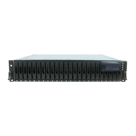
Proware Fibre to SAS/SATA II RAID Subsystem User manual
Proware
Proware DP-503-F4A3 User manual
Proware
Proware EN-2126JS6-SQX User manual
Proware
Proware EP-3164D-GAS3 User manual
Proware
Proware EP-3163J/JD-SCSC User manual
Proware
Proware EP-2126-SS User manual
Proware
Proware SB-1413-UA Manual
Proware
Proware EP-3163S-F8S6 User manual
