Proware SB-1413-UA Manual

USB and eSATA to SATA II
RAID Subsystem
Installation and Configuration
Manual
Revision 1.0
P/N: PW020000000348

USB and eSATA to SATA II RAID Subsystem
Installation and Configuration Manual 2
Table of Contents
Preface ............................................................................................................ 5
Before You Begin.......................................................................................... 6
Safety Guidelines...................................................................................................................................................6
Controller Configuration....................................................................................................................................6
Packaging, Shipment and Delivery ...............................................................................................................6
Unpacking the Subsystem ................................................................................................................................7
Chapter 1 Introduction ............................................................................. 8
1.1 Key Features .................................................................................................................................................9
1.2 Identifying Parts of the RAID Subsystem......................................................................................10
1.2.1 Front View...........................................................................................................................................10
1.2.2 Rear View ............................................................................................................................................13
1.3 Technical Specifications.........................................................................................................................14
1.4 RAID Concepts ..........................................................................................................................................15
1.5 Array Definition.........................................................................................................................................19
1.5.1 Raid Set................................................................................................................................................19
1.5.2 Volume Set.........................................................................................................................................19
1.5.3 Easy to Use Features .....................................................................................................................20
1.5.3.1 Instant Availability/Background Initialization ..............................................................20
1.5.3.2 Array Roaming .........................................................................................................................20
1.5.3.3 Online Capacity Expansion..................................................................................................20
1.3.3.4 Online RAID Level and Stripe Size Migration.............................................................21
1.5.4 High Availability..............................................................................................................................22
1.5.4.1 Creating Hot Spares ...............................................................................................................22
1.5.4.2 Hot-Swap Disk Drive Support............................................................................................22
1.3.4.3 Hot-Swap Disk Rebuild.........................................................................................................22
Chapter 2 Getting Started...................................................................... 23
2.1 Preparing the Subsystem and Powering On ...............................................................................23
2.2 Installing Hard Drives.............................................................................................................................23

USB and eSATA to SATA II RAID Subsystem
3Installation and Configuration Manual
Chapter 3 RAID Configuration .............................................................. 25
3.1 Configuring Through a Terminal........................................................................................................25
3.2 Configuring Using the LCD Panel......................................................................................................30
3.3 Menu Diagram ..........................................................................................................................................32
3.4 Web browser-based Remote RAID management via R-Link Port.....................................38
3.5 Quick Create..............................................................................................................................................40
3.6 Raid Set Functions...................................................................................................................................41
3.6.1 Create Raid Set.................................................................................................................................41
3.6.2 Delete Raid Set .................................................................................................................................42
3.6.3 Expand Raid Set................................................................................................................................42
3.6.4 Offline Raid Set.................................................................................................................................44
3.6.5 Activate Incomplete Raid Set .....................................................................................................45
3.6.6 Create Hot Spare .............................................................................................................................47
3.6.7 Delete Hot Spare .............................................................................................................................47
3.6.8 Rescue Raid Set.................................................................................................................................48
3.7 Volume Set Function .............................................................................................................................49
3.7.1 Create Volume Set ..........................................................................................................................49
3.7.2 Delete Volume Set...........................................................................................................................51
3.7.3 Modify Volume Set .........................................................................................................................52
3.7.3.1 Volume Expansion...................................................................................................................53
3.7.4 Volume Set Migration ................................................................................................................53
3.7.5 Check Volume Set............................................................................................................................54
3.7.6 Stop Volume Set Check.................................................................................................................55
3.8 Physical Drive............................................................................................................................................55
3.8.1 Create Pass-Through Disk ............................................................................................................55
3.8.2 Modify Pass-Through Disk...........................................................................................................56
3.8.3 Delete Pass-Through Disk ............................................................................................................57
3.8.4 Identify Selected Drive ..................................................................................................................57
3.9 System Controls.......................................................................................................................................58
3.9.1 System Configuration.....................................................................................................................58
3.9.2 EtherNet Config................................................................................................................................60
3.9.3 Alert By Mail Config.......................................................................................................................61
3.9.4 SNMP Configuration.......................................................................................................................62
3.9.5 NTP Configuration ...........................................................................................................................63
3.9.6 View Events/Mute Beeper ............................................................................................................64
3.9.7 Generate Test Event ........................................................................................................................65

USB and eSATA to SATA II RAID Subsystem
Installation and Configuration Manual 4
3.9.8 Clear Event Buffer.............................................................................................................................65
3.9.9 Modify Password..............................................................................................................................66
3.9.10 Upgrade Firmware .........................................................................................................................66
3.9.11 Restart Controller..........................................................................................................................66
3.10 Information Menu ................................................................................................................................67
3.10.1 RaidSet Hierarchy ...........................................................................................................................67
3.10.2 System Information........................................................................................................................69
3.10.3 Hardware Monitor .........................................................................................................................70
3.11 Creating New Raid Set or Reconfiguring an Existing Raid Set.........................................71
3.12 Upgrading the Firmware......................................................................................................................72
USB and eSATA to SATA II RAID Subsystem
5Installation and Configuration Manual
Preface
About this manual
This manual provides information regarding the quick installation and hardware features of the
RAID subsystem. This document also describes how to use the storage management software.
Information contained in the manual has been reviewed for accuracy, but not for product warranty
because of the various environment/OS/settings. Information and specifications will be changed
without further notice.
This manual uses section numbering for every topics being discussed for easy and convenient way
of finding information in accordance with the user’s needs. The following icons are being used for
some details and information to be considered in going through with this manual:
Copyright
No part of this publication may be reproduced, stored in a retrieval system, or transmitted in any
form or by any means, electronic, mechanical, photocopying, recording or otherwise, without the
prior written consent.
Trademarks
All products and trade names used in this document are trademarks or registered trademarks of
their respective holders.
Changes
The material in this document is for information only and is subject to change without notice.
IMPORTANT!
These are the important information that the user must remember.
WARNING!
These are the warnings that the user must follow to avoid
unnecessary errors and bodily injury during hardware and software
operation of the subsystem.
CAUTION:
These are the cautions that user must be aware to prevent damage
to the equipment and its components.
NOTES:
These are notes that contain useful information and tips that the
user must give attention to in going through with the subsystem
operation.

USB and eSATA to SATA II RAID Subsystem
Installation and Configuration Manual 6
Before You Begin
Before going through with this manual, you should read and focus to the following safety
guidelines. Notes about the subsystem’s controller configuration and the product packaging and
delivery are also included.
Safety Guidelines
To provide reasonable protection against any harm on the part of the user and to obtain maximum
performance, user is advised to be aware of the following safety guidelines particularly in handling
hardware components:
Upon receiving of the product:
Place the product in its proper location.
To avoid unnecessary dropping out, make sure that somebody is around for immediate
assistance.
It should be handled with care to avoid dropping that may cause damage to the product.
Always use the correct lifting procedures.
Upon installing of the product:
Ambient temperature is very important for the installation site. It must not exceed 30◦C. Due to
seasonal climate changes; regulate the installation site temperature making it not to exceed
the allowed ambient temperature.
Before plugging-in any power cords, cables and connectors, make sure that the power switches
are turned off. Disconnect first any power connection if the power supply module is being
removed from the enclosure.
Outlets must be accessible to the equipment.
All external connections should be made using shielded cables and as much as possible should
not be performed by bare hand. Using anti-static hand gloves is recommended.
In installing each component, secure all the mounting screws and locks. Make sure that all
screws are fully tightened. Follow correctly all the listed procedures in this manual for reliable
performance.
Controller Configuration
This RAID subsystem supports single controller configuration.
Packaging, Shipment and Delivery
Before removing the subsystem from the shipping carton, you should visually inspect the
physical condition of the shipping carton.
Unpack the subsystem and verify that the contents of the shipping carton are all there and in
good condition.
Exterior damage to the shipping carton may indicate that the contents of the carton are
damaged.
If any damage is found, do not remove the components; contact the dealer where you purchased the
subsystem for further instructions.
USB and eSATA to SATA II RAID Subsystem
7Installation and Configuration Manual
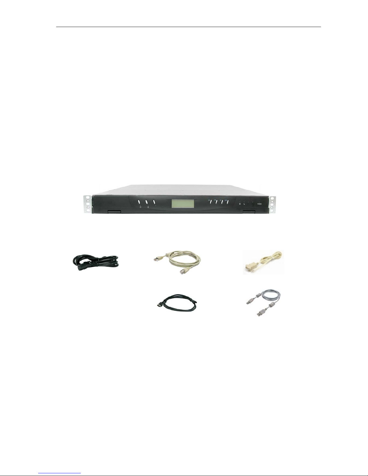
Unpacking the Subsystem
The package contains the following items:
• RAID subsystem unit
• One power cord
• One RJ-45 Ethernet cable
• One external serial cable (RJ-11 to DB9)
• One external SATA cable
• One USB cable
• Installation Reference Guide
• Spare screws, etc.
USB and eSATA to SATA II RAID Subsystem
Installation and Configuration Manual 8
Chapter 1 Introduction
The RAID Subsystem
Unsurpassed Value
Most cost-effective SATA II RAID Subsystem
Application Flexibility
Extends useful life by adapting to future IT requirements
Easy Installation, upgrade & Maintenance
Provide a fast and easy way to install and upgrade the storage. Simplified maintenance reduces
ongoing IT labor costs.
Exceptional Manageability
Graphical User Interface (GUI) provides easy way for users to remotely manage and configure
the storage
Menu-driven LCD front panel makes it convenient for users to locally manage the storage
Green Power Concept
Saves power by adopting the new technology “MAID” (Massive Arrays of Idle Disks).

USB and eSATA to SATA II RAID Subsystem
9Installation and Configuration Manual
1.1 Key Features
Subsystem Features:
eSATA (3Gbps) / USB 2.0 (480Mbps) dual host interface
Multiple Volumes for host access.
Over 2TB support
Supports hot spare and automatic hot rebuild
Allows online capacity expansion within the enclosure
Local audible event notification alarm
Supports password protection
Built-in serial port interface for remote event notification
Tagged command queuing for 256 commands, allows for overlapping data streams
Transparent data protection for all popular operating systems
RAID Management:
Smart-function LCD panel
Environmental monitoring unit
Real time drive activity and status indicators
Web-based GUI management utility
USB and eSATA to SATA II RAID Subsystem
Installation and Configuration Manual 10
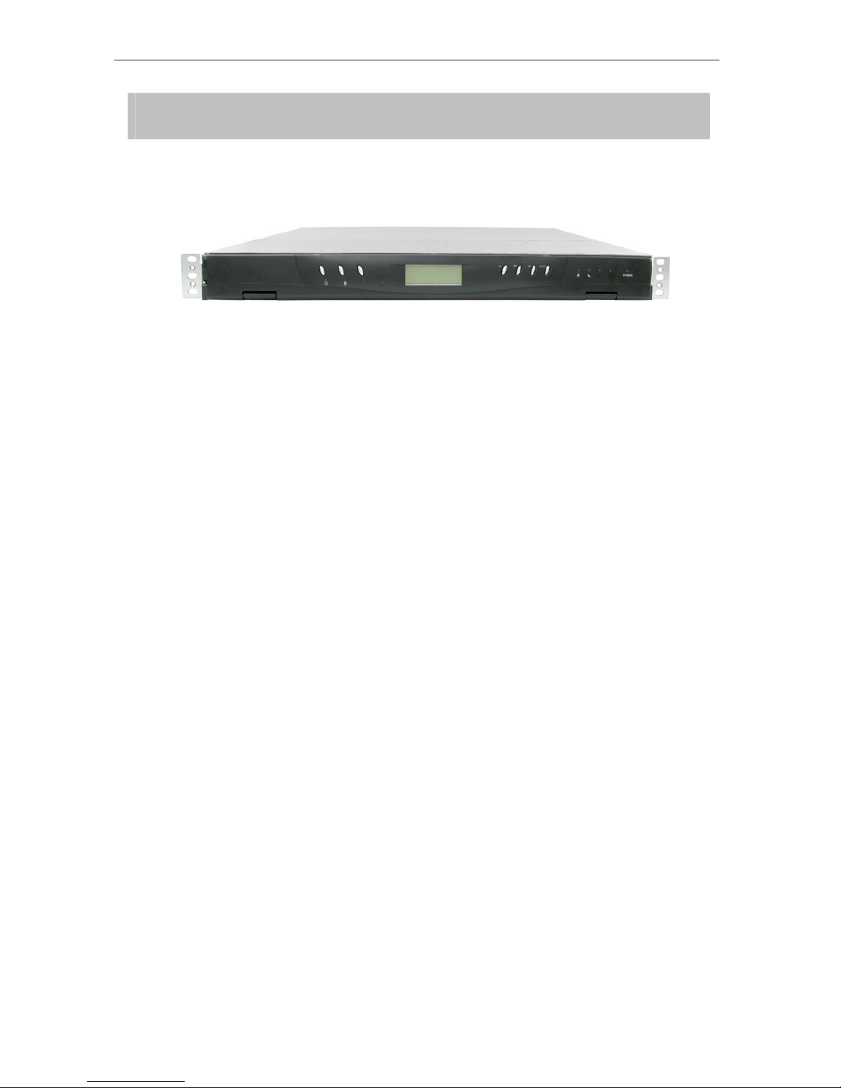
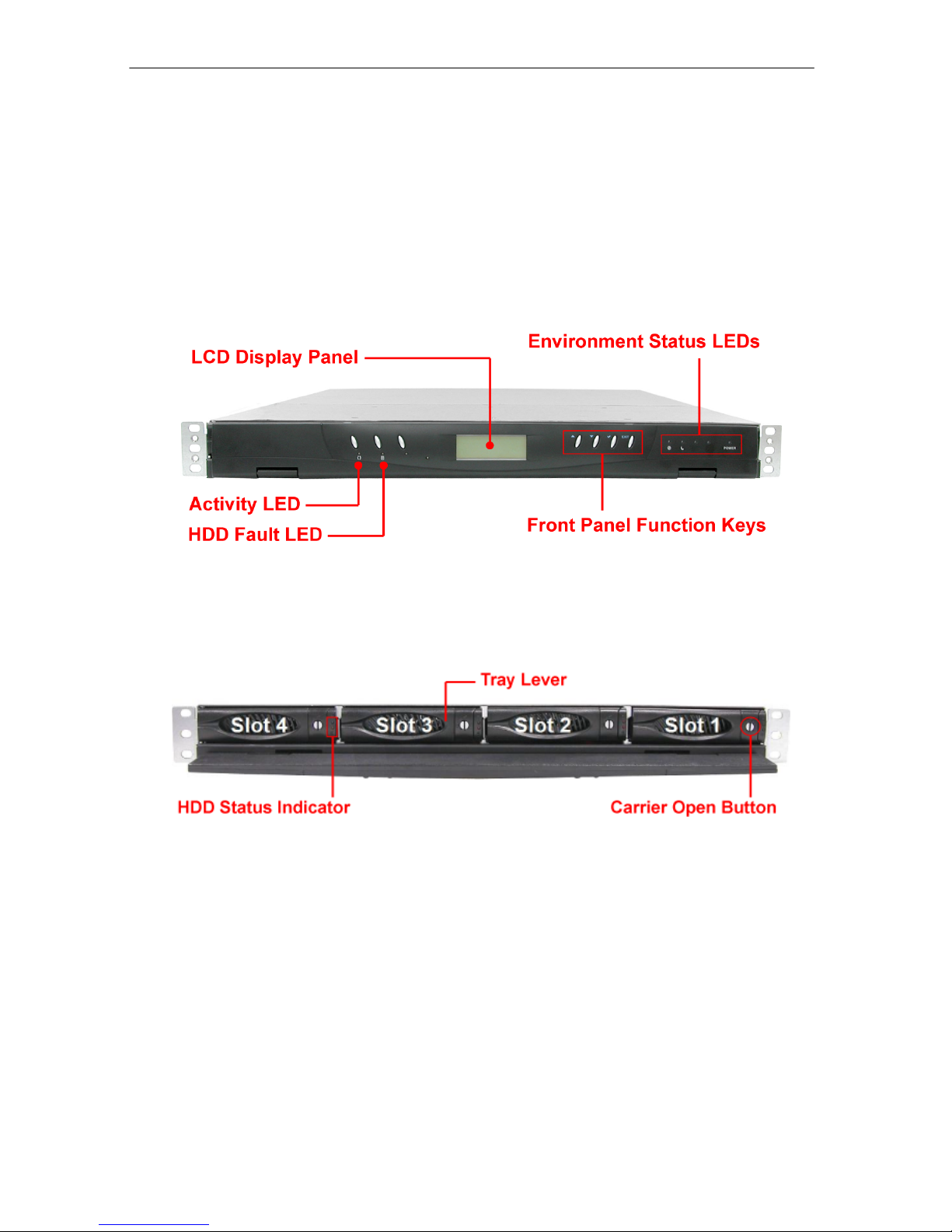
1.2 Identifying Parts of the RAID Subsystem
The illustrations below identify the various parts of the subsystem.
1.2.1 Front View

USB and eSATA to SATA II RAID Subsystem
11 Installation and Configuration Manual
1. HDD Status Indicator
There are two LED indicators for each disk drive.
Part Function
HDD Status LED
No LED light indicates power is on and hard drive status is
good for this slot. Red means no disk drive inserted or disk
drive is Faulty.
HDD Access LED
LED will blink blue when the hard drive is being accessed.
2. Lock Indicator
Every Drive Tray is lockable inside the slots. Open the door lock. When the lock indicator is in
vertical position (arrow points downwards), the drive tray is unlocked. When the lock indicator is in
horizontal position (arrow points to the left), the drive tray is locked. To lock a drive tray, use a
special key and turn the lock indicator.
USB and eSATA to SATA II RAID Subsystem
Installation and Configuration Manual 12
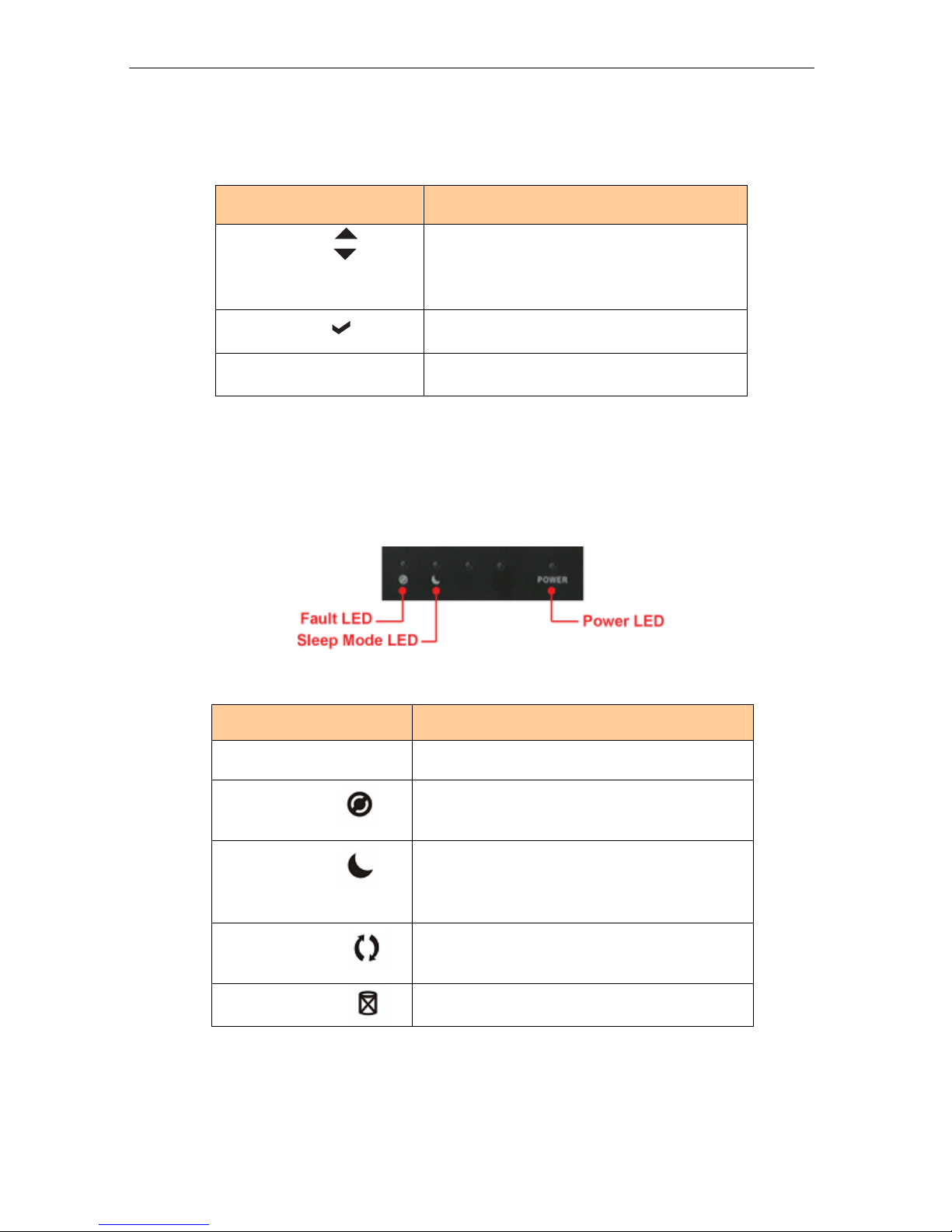
3. Front Panel Function Keys
Use the function keys to navigate through the menu options available.
Parts Function
Up and Down
Arrow buttons
Use the Up or Down arrow keys to go through
the information on the LCD screen. This is also
used to move between each menu when you
configure the subsystem.
Select button This is used to enter the option you have
selected.
Exit button EXIT Press this button to return to the previous
menu.
4. Environment Status LEDs
Parts Function
Power LED POWER Green LED indicates power is ON.
Fault LED Red blinking LED indicates a problem within the
internal subsystem, such as over temperature.
Sleep Mode LED Red LED is normal and subsystem is not in sleep
mode. Red blinking LED means subsystem is in
sleep mode (spin down idle HDD).
Activity LED This LED will blink blue when the RAID controller
is busy / active.
HDD Fault LED This LED will blink red when there is HDD failure.
USB and eSATA to SATA II RAID Subsystem
13 Installation and Configuration Manual
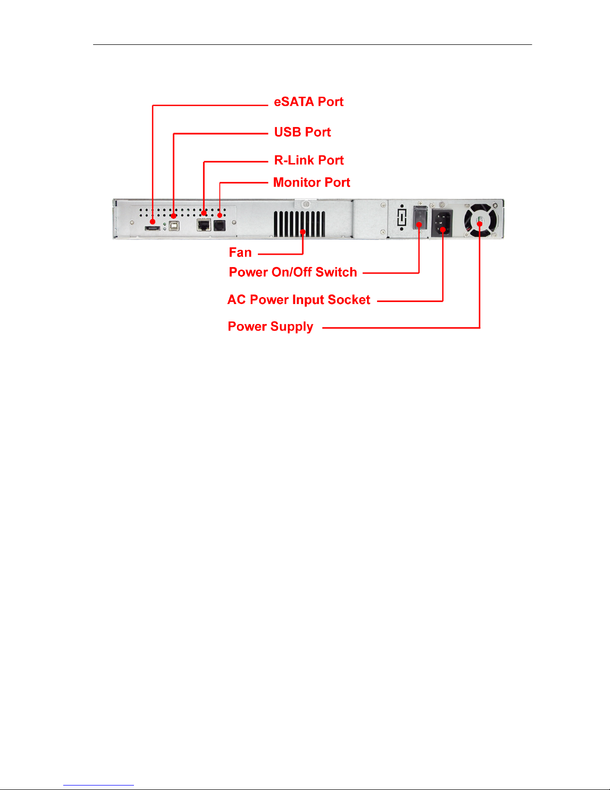
1.2.2 Rear View
1. eSATA Port
The subsystem has one external SATA II port for connecting to the host system or server.
2. USB Port
The subsystem has one USB 2.0 port for connecting to the host system or server.
3. R-Link Port: Remote Link through RJ-45 Ethernet for remote management
The subsystem is equipped with one 10/100 Ethernet RJ45 LAN port. You use a web browser to
manage the RAID subsystem through Ethernet for remote configuration and monitoring.
Link LED: Green LED indicates Ethernet is linking.
Access LED: The LED will blink orange when the 100Mbps Ethernet is being accessed.
4. Monitor Port
The subsystem is equipped with a serial monitor port allowing you to connect a PC or terminal.

USB and eSATA to SATA II RAID Subsystem
Installation and Configuration Manual 14
1.3 Technical Specifications
Feature Specification
Form-factor 1U 19-inch rackmount chassis
RAID processor 400MHz storage I/O processor
RAID level 0, 1, 0+1, 3, 5 and JBOD
Cache memory 128MB
No. of Channels (Host and Drive) 2 and 4
Host bus interface USB 2.0 / eSATA
Drive bus interface SATA II (Up to 3.0Gbps)
Data transfer rate Up to 480Mbits (USB 2.0) / Up to 3.0Gbps
(SATA II)
Back plane board SATA II
Hot-swap drive tray Four (4) 1-inch trays
Power supply 220W power supply w/PFC
Cooling fan 1
Password protection Yes
Audible alarm Yes
Failed drive indicators Yes
Failed drive auto rebuild Yes
Online consistency check Yes
Online expansion Yes
Array Roaming Yes
Online RAID level/ stripe size
migration Yes
Instant availability and background
initialization Yes
Environment monitor Yes
Auto spare support Yes
Bad block auto-remapping Yes
Remote management Yes
MAID support Yes
Power requirements AC 90V ~ 264V full range
6A ~ 3A, 50Hz ~ 60Hz
Relative Humidity: 10% ~ 85% Non-condensing
Operating Temp: 10oC ~ 40oC (50oF ~ 104oF)
Physical Dimensions: 44.4(H) x 486.4(W) x 569(D)mm
Weight 7.6Kg (without drives)
USB and eSATA to SATA II RAID Subsystem
15 Installation and Configuration Manual
1.4 RAID Concepts
RAID Fundamentals
The basic idea of RAID (Redundant Array of Independent Disks) is to combine multiple inexpensive disk
drives into an array of disk drives to obtain performance, capacity and reliability that exceeds that of a
single large drive. The array of drives appears to the host computer as a single logical drive.
Five types of array architectures, RAID 1 through RAID 5, were originally defined; each provides disk
fault-tolerance with different compromises in features and performance. In addition to these five
redundant array architectures, it has become popular to refer to a non-redundant array of disk drives
as a RAID 0 arrays.
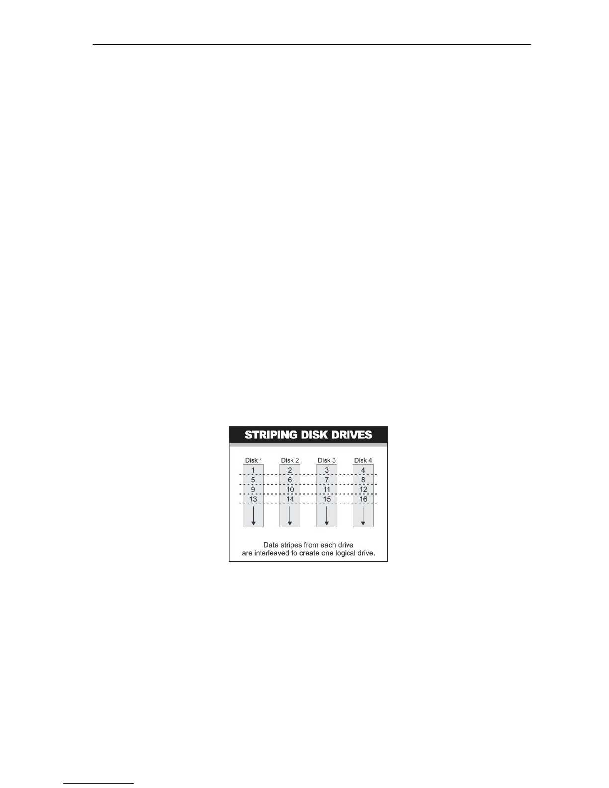
Disk Striping
Fundamental to RAID technology is striping. This is a method of combining multiple drives into one
logical storage unit. Striping partitions the storage space of each drive into stripes, which can be as
small as one sector (512 bytes) or as large as several megabytes. These stripes are then interleaved in
a rotating sequence, so that the combined space is composed alternately of stripes from each drive.
The specific type of operating environment determines whether large or small stripes should be used.
Most operating systems today support concurrent disk I/O operations across multiple drives. However,
in order to maximize throughput for the disk subsystem, the I/O load must be balanced across all the
drives so that each drive can be kept busy as much as possible. In a multiple drive system without
striping, the disk I/O load is never perfectly balanced. Some drives will contain data files that are
frequently accessed and some drives will rarely be accessed.
By striping the drives in the array with stripes large enough so that each record falls entirely within one
stripe, most records can be evenly distributed across all drives. This keeps all drives in the array busy
during heavy load situations. This situation allows all drives to work concurrently on different I/O
operations, and thus maximize the number of simultaneous I/O operations that can be performed by
the array.
USB and eSATA to SATA II RAID Subsystem
Installation and Configuration Manual 16
Definition of RAID Levels
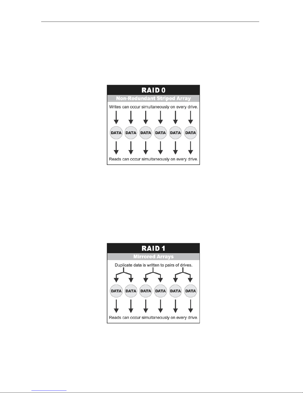
RAID 0 is typically defined as a group of striped disk drives without parity or data redundancy. RAID 0
arrays can be configured with large stripes for multi-user environments or small stripes for single-user
systems that access long sequential records. RAID 0 arrays deliver the best data storage efficiency and
performance of any array type. The disadvantage is that if one drive in a RAID 0 array fails, the entire
array fails.
RAID 1, also known as disk mirroring, is simply a pair of disk drives that store duplicate data but
appear to the computer as a single drive. Although striping is not used within a single mirrored drive
pair, multiple RAID 1 arrays can be striped together to create a single large array consisting of pairs of
mirrored drives. All writes must go to both drives of a mirrored pair so that the information on the
drives is kept identical. However, each individual drive can perform simultaneous, independent read
operations. Mirroring thus doubles the read performance of a single non-mirrored drive and while the
write performance is unchanged. RAID 1 delivers the best performance of any redundant array type. In
addition, there is less performance degradation during drive failure than in RAID 5 arrays.
USB and eSATA to SATA II RAID Subsystem
17 Installation and Configuration Manual
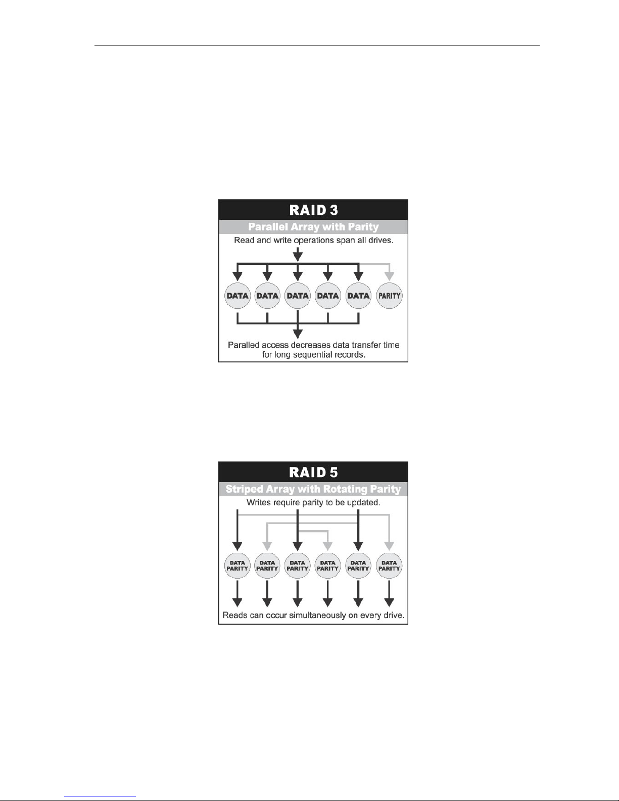
RAID 3 sector-stripes data across groups of drives, but one drive in the group is dedicated to storing
parity information. RAID 3 relies on the embedded ECC in each sector for error detection. In the case
of drive failure, data recovery is accomplished by calculating the exclusive OR (XOR) of the information
recorded on the remaining drives. Records typically span all drives, which optimizes the disk transfer
rate. Because each I/O request accesses every drive in the array, RAID 3 arrays can satisfy only one
I/O request at a time. RAID 3 delivers the best performance for single-user, single-tasking
environments with long records. Synchronized-spindle drives are required for RAID 3 arrays in order to
avoid performance degradation with short records. RAID 5 arrays with small stripes can yield similar
performance to RAID 3 arrays.
Under RAID 5 parity information is distributed across all the drives. Since there is no dedicated parity
drive, all drives contain data and read operations can be overlapped on every drive in the array. Write
operations will typically access one data drive and one parity drive. However, because different records
store their parity on different drives, write operations can usually be overlapped.
Dual-level RAID achieves a balance between the increased data availability inherent in RAID 1 and
the increased read performance inherent in disk striping (RAID 0). These arrays are sometimes referred
to as RAID 0+1 or 1+0.

USB and eSATA to SATA II RAID Subsystem
Installation and Configuration Manual 18
In summary:
RAID 0 is the fastest and most efficient array type but offers no fault-tolerance. RAID 0 requires a
minimum of one drive.
RAID 1 is the best choice for performance-critical, fault-tolerant environments. RAID 1 is the only
choice for fault-tolerance if no more than two drives are used.
RAID 3 can be used to speed up data transfer and provide fault-tolerance in single-user
environments that access long sequential records. However, RAID 3 does not allow overlapping of
multiple I/O operations and requires synchronized-spindle drives to avoid performance degradation
with short records. RAID 5 with a small stripe size offers similar performance.
RAID 5 combines efficient, fault-tolerant data storage with good performance characteristics.
However, write performance and performance during drive failure is slower than with RAID 1.
Rebuild operations also require more time than with RAID 1 because parity information is also
reconstructed. At least three drives are required for RAID 5 arrays.
RAID Management
The subsystem can implement several different levels of RAID technology. RAID levels supported by
the subsystem are shown below.
RAID Level Description Min. Drives
0
Block striping is provide, which yields higher
performance than with individual drives. There is no
redundancy.
1
1 Drives are paired and mirrored. All data is 100%
duplicated on an equivalent drive. Fully redundant. 2
3 Data is striped across several physical drives. Parity
protection is used for data redundancy. 3
5 Data is striped across several physical drives. Parity
protection is used for data redundancy. 3
1 + 0 Combination of RAID levels 0 and 1. This level provides
redundancy through mirroring and striping. 4
USB and eSATA to SATA II RAID Subsystem
19 Installation and Configuration Manual
1.5 Array Definition
1.5.1 Raid Set
A Raid Set is a group of disk drives containing one or more logical volumes called Volume Sets. It is
not possible to have multiple Raid Sets on the same disk drives.
A Volume Set must be created either on an existing Raid Set or on a group of available individual disk
drives (disk drives that are not yet a part of a Raid Set). If there are existing Raid Sets with available
raw capacity, new Volume Set can be created. New Volume Set can also be created on an existing
Raid Set without free raw capacity by expanding the Raid Set using available disk drive(s) which
is/are not yet Raid Set member. If disk drives of different capacity are grouped together in a Raid Set,
then the capacity of the smallest disk will become the effective capacity of all the disks in the Raid
Set.
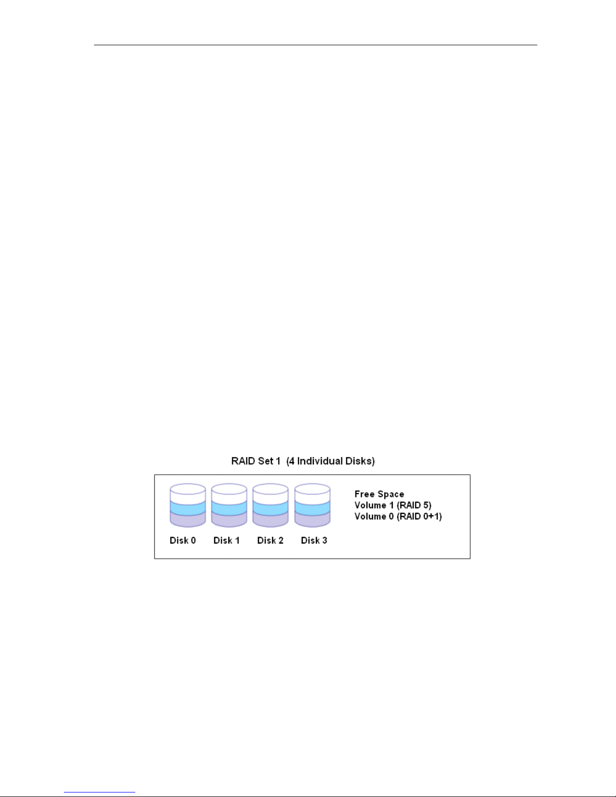
1.5.2 Volume Set
A Volume Set is seen by the host system as a single logical device. It is organized in a RAID level
with one or more physical disks. RAID level refers to the level of data performance and protection of
a Volume Set. A Volume Set capacity can consume all or a portion of the r a w capacity available
in a Raid Set. Multiple Volume Sets can exist on a group of disks in a Raid Set. Additional Volume
Sets created in a specified Raid Set will reside on all the physical disks in the Raid Set. Thus each
Volume Set on the Raid Set will have its data spread evenly across all the disks in the Raid Set.
Volume Sets of different RAID levels may coexist on the same Raid Set.
In the illustration below, Volume 1 can be assigned a RAID 5 level while Volume 0 might be assigned
a RAID 0+1 level.
USB and eSATA to SATA II RAID Subsystem
Installation and Configuration Manual 20
1.5.3 Easy to Use Features
1.5.3.1 InstantAvailability/Background Initialization
RAID 0 and RAID 1 Volume Set can be used immediately after the creation. But the RAID 3, 5 and 6
Volume Sets must be initialized to generate the parity. In the Background Mode initialization, the
initialization proceeds as a background task, the Volume Set is fully accessible for system reads and
writes. The operating system can instantly access to the newly created Volume Sets without waiting for
the initialization to be completed. One disadvantage of this is that the initialization process takes longer
time. In Foreground Mode initialization, the initialization process is faster but must be completed first
before the Volume Set is ready for system access.
1.5.3.2 Array Roaming
The RAID subsystem stores configuration information both in NVRAM and on the disk drives. This
protects the configuration settings in the case of a disk drive or controller failure. Array roaming allows
the administrator the ability to move a complete Raid Set to another system without losing RAID
configuration and data on that Raid Set. If a RAID enclosure fails to work, the Raid Set disk drives can
be moved to another enclosure and inserted in any order.
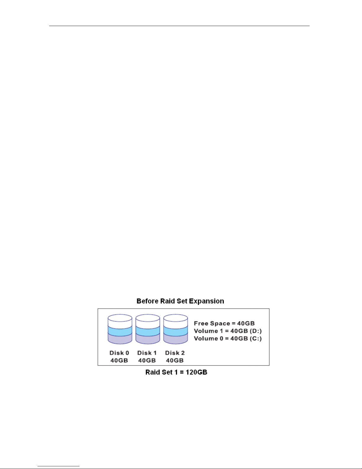
1.5.3.3 Online Capacity Expansion
Online Capacity Expansion makes it possible to add one or more physical drives to a Raid Set, while the
server is in operation, eliminating the need to backup and restore after reconfiguring the Raid Set.
When disks are added to a Raid Set, unused capacity is added at the end of the Raid Set. Data on the
existing Volume Sets residing on that Raid Set is redistributed evenly across all the disks. A contiguous
block of unused capacity is made available on the Raid Set. The unused capacity can be used to create
additional Volume Set. The expansion process is illustrated as follows.
Table of contents
Other Proware Storage manuals

Proware
Proware EN-2126JS6-SQX User manual

Proware
Proware EP-4246J-S6S6 User manual

Proware
Proware EP-3163S-F8S6 User manual

Proware
Proware EP-2126-SA3 User manual

Proware
Proware EP-2126-SS User manual

Proware
Proware EP-3164D-GAS3 User manual

Proware
Proware DP-503-F4A3 User manual

Proware
Proware EN-1400A6B-CM User manual

Proware
Proware Fibre to SAS/SATA II RAID Subsystem User manual

Proware
Proware EP-3163J/JD-SCSC User manual


