PS Motor Manet Korado User manual
·~
·
moped
Owner's
Manual
moped
Owner's
Manual

The moped KORADO is a vehicle used for transport on roads with reinforced sur-
face
to
bring you to work
or
to
spend free time for leisure and sports.
The vehicle is driven with a reliable PUCH motor which is built under licence and
together with easy operation guarantees safe, comfortable and economic driving. It
has a massive frame, good ergonomical parameters and a modern design. Among its
other advantages belong long life, high performance, economical operat
io
n and a
reasonable price.
Read this ma
nu
al
before your fi
rs
t drivi1g
to
learn how
to
operate the moped and
respect recommendations included
in
this manual.
Th
e KORADO moped went thro-
u
gt
·,
t
or1g-
tirn~
t~st
ing
and its modern production technology a
nd
tr
ad
ition is a
gu
aran-
tee of its high European quality standard. •
We wish you many troublefree and safe kilometers on your new moped.
PS MOTOR MANET a. s.
Povazska Bystrica
The producer reserves the right to change the text and pictures
in
this manual.
2
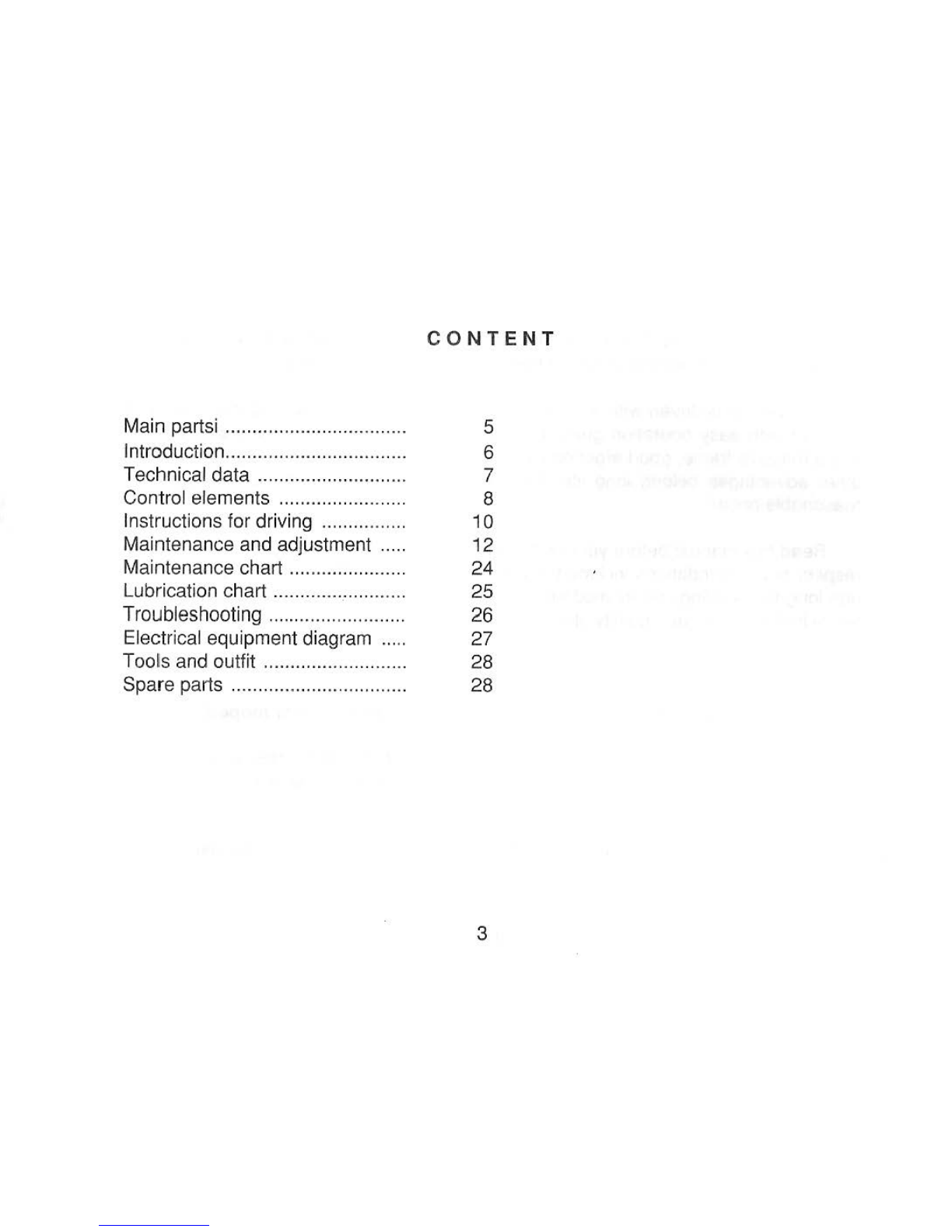
CONTENT
Main partsi ..
..
..........
..
......
...
..
....
..
. 5
Introduction.................................. 6
Technical data
..
............
.
..
........
..
. 7
Control elements ...............
......
..
. 8
Instructions for driving ................ 10
Maintenance and adjustment
..
..
. 12
Maintenance chart
....
......
..
.....
....
. 24
Lubrication chart
..
..............
..
....
..
.
25
Troubleshooting ............
....
.......
..
. 26
Electrical equipment diagram
....
. 27
Tools and outfit
..
........
..
........
..
....
. 28
Spare parts
..
..
......
..
....
..
..........
..
..
. 28
3
22
21
zo
12
f1
fO
8
l3
14
15
16
11
23
18
2~
19
1 2 3
4

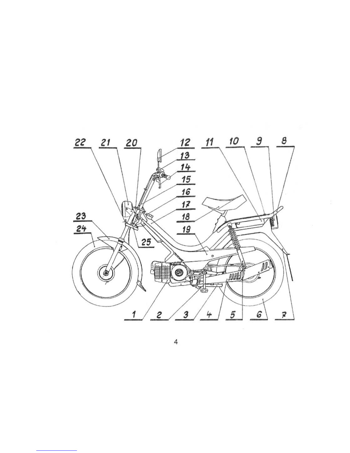
Fig. 1 KORADO
Moped-
ma
in parts
1.
Engine
2. Pedals
3.
Stand
4.
Exhaust silencer
5.
Telescopic rear suspension
6. Rear wh
ee
l
7.
Rear mudguard
8. Luggage rack
9. Rear light
1
0.
Air-release valve
11. Tool kit
12.
Rear-view mirror
13. Be
ll
14. Cont
ro
l levers
1
5.
Handlebars
1
6.
Filler cap
1
7.
Frame
18. Saddle
19. Side covers
20. Teleskopic front suspension
21
. Headlight
22. Front reflecting glass
23. Front
mu
dguard
24. Front wheel
25.Lock
5
1.
In
troduction
-Takeover of the motorcycle
Control the outfit for completeness according to the documentation when taking
over the motorcycle.
-Control the serial number if
it
coincides with the documentation-the serial num-
ber
is
located on the upper part of the frame and is readable from
th
e right side of the
motor. The motor number need not be identical with the number of the chassi
s.
Get
acquainted with the main parts and control elements before your first drive (fig. 1).
-AT
T E
NT
I 0 N -You have bought a two-stroke engine. It is therefore neces-
sary
to
mix the main fuel -gasoline with oil
in
the ratio 1:33 when breaking-in and
1:40 after breaking-
in
the engine. Use fuel with octane number 95 and oil SHELL-
SUPER
2T
. When using synthetic oil SHELL SUPER 2TX the mixing ratio is 1:50.
6
2. T
ec
hni
ca
ldata
Engine
Displacement
Bore/stroke
Maximal output
Gear box
Starting clutch
Run-up clutch
Primary transmission
Secondary transmission
Bicycle transmission
Front suspension
Rear suspension
Brakes
Brake dimensions
Tyres
Inflation pressures
-front
tyre
-reartyre
Overall weight
Moped dry
we
i
ght
Max
. speed
Single-cylinder two-stroke air-cooled
48.8 cm3
38/43 mm
2
kW
I 4500 r.p.m.
automatic one-stage
wet, mechanical
wet, mechanical
by means of
gea
r 1:5.052
by means of a roller chain 1:3.000
by means of a roller chain 1:0.785
telescopic firk with shock absorber -stroke
80
mm
telescope with shock absorber -stroke 60 mm
expanding shoe-brakes controlled by levers
on
handle
bars
85 x20 mm
2 1/4 X 16"
2 atp (196 kPa)
30
1
~!i!
2,5
atp
(245 kPa) .l
~
f's
1
145 kg
57,5 kg )
.z.
tJ
t6
40
km/h
7
Fuel tank capacity
Hill-climbing capacity
Noise
Basic fuel consumption
Carburettor
Power supply
Ignition
Spark advance
Spark plug
Head
lamp
Tail
lamp
41
14%
72
dB
(A)
1,7 1/100
km
at 27 km/h
BING 18/
14
/
108
alternator 6 V/
20
W
flywheel
magnet
-
type
contact ignition
1.2
-
1.4
mm,
gap
0,4 mm
BOSCH W 5 AC
6 V/15 W
6 V/5 W
3. Control elements (fig. 2)
The following elements are on right side
of
the handlebar:
-throtle
co
ntrol (1)
-front br
ake
l
ever
(2)
-choke
(3)
-engine stop push button (8)
alternat
or
12 V/40 W
flywheel magnet-type
contactless ignition
1,2-1,4 mm
BOSCH
W5
AC
12 V/15 W
12
V/5
W
The
following elements are on the left side
of
the handlebar:
-firm
grip (4)
-rear brake lever (5)
- starting clutch lever (6)
-lights switch (7)
8
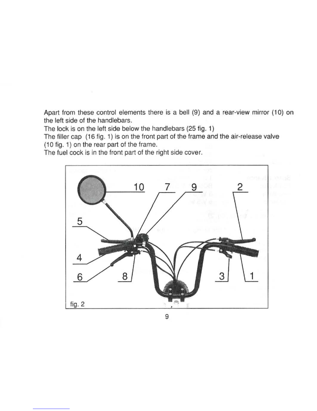
Apart from these control el
ements
there is a bell (9) and a rear-
view
mirror (1
0)
on
the left side of the handlebars.
The
lock
is
on the left side bel
ow
the handlebars (25 fig. 1)
The
filler
cap
{
16
fig. 1)
is
on the front part
of
the frame and the air-release
valve
(10 fig.
1)
on the rear part of the frame.
The fuel
cock
is in the front part
of
the right side cover.
9 2
5
4
8 3 1
fig. 2 •
9
4. Instructions for driving
Fill the tank with the gas-oil mixture befo
re
drivi
ng
as follows:
Unscrew the cap of the tank and release the air-release valve which
is
in
the upper
rear part of the frame. Fill t
he
tank up to the mark which is a wire sieve
in
the filler
neck. Close the air-release valve after refilling by tightening the screw and put on the
fi
ll
er
cap.
AT
TENT
I 0 N I The air-release valve can not be loosened after
fi
lling the tank. it
could cause fuel leaking through the ventilation hole of the filler cap. If it is not possi-
ble
to
fill the
ga
s-oil mixture automatically
at
the petrol station mix the fuel
in
a vessel
before refilling the
ta
nk.
Check
th
e following before
dr
iv
in
g:
-correct function of the brakes
- inflation pressure
- function of lights
-
ti
ghening of
th
e chain
Drive wi
th
the heal
ig
ht on according to the traffic r
eg
ul
ations.
10
Starti
ng
the moped
You can start the moped
in
two ways: a)
on
the stand
b) with moving vehicle by pedaling
a)
Starting with stationary vehicle
is
more common:
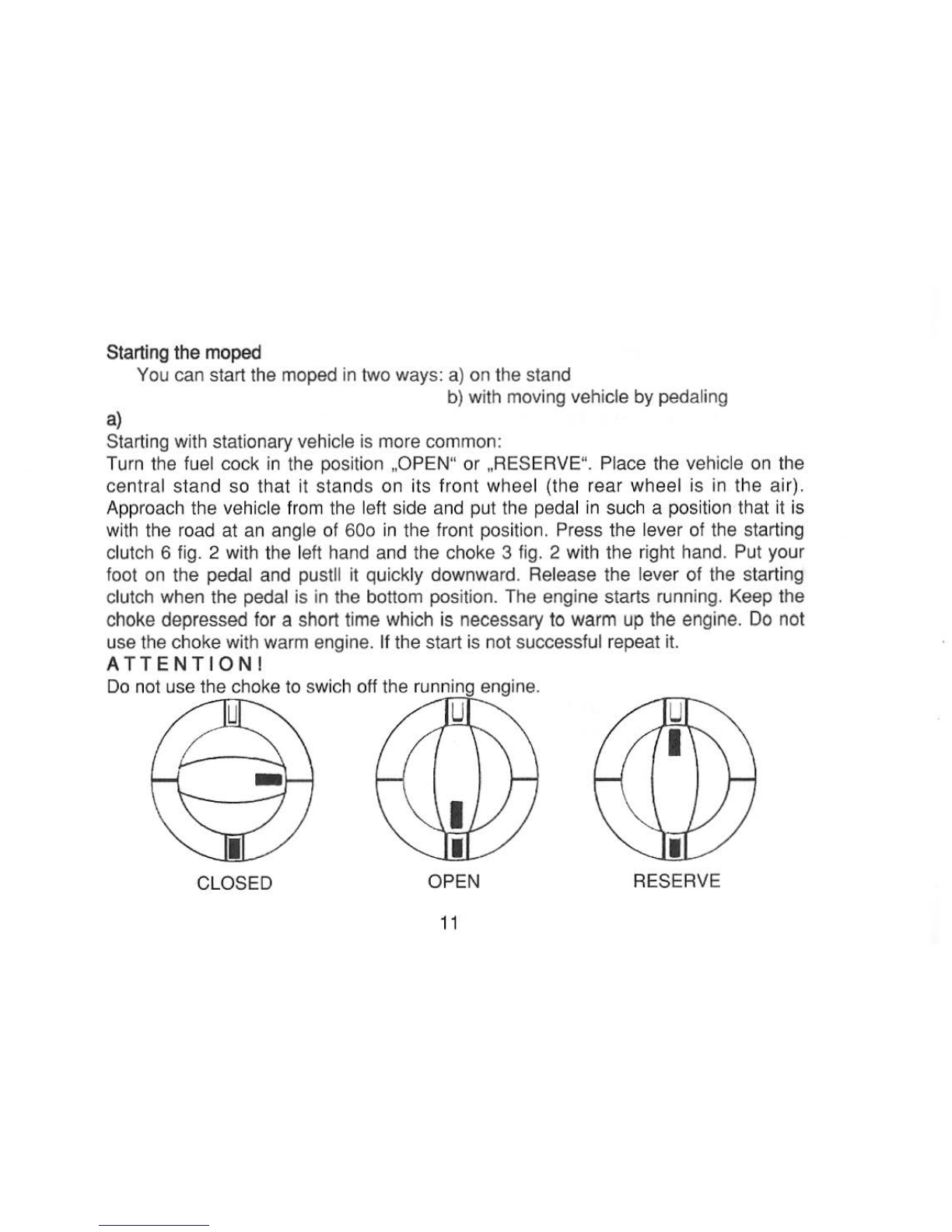
Turn the fuel cock
in
the position ,OPEN" or ,RESERVE". Place the vehicle
on
the
central stand so that it stands on its front wheel (the rear wheel is
in
the air).
Approach t
he
vehicle fr
om
the left side and put the pedal in such a position that it is
with the road at
an
angle of 60o
in
the front posit
ion.
Press the lever of the starting
clutch 6 fig. 2 with the left hand and the choke 3 fig. 2 with the right hand. Put your
foot
on
the pedal and pustll it quickly downward. Release the lever of the starting
clutch when the pedal is in the bottom position. The engine starts runni
ng.
Keep the
choke depressed for a short time which is necessary to warm up the engine.
Do
not
use the choke with warm engine. If the start
is
not successful repeat it.
A T T E
NTI
O
N!
Do
not use the choke to swich off the r
un
n
ing
engine.
u u
CLOSED OP
EN
RESERVE
11

b)
Starting by pedaling
Put the fuel cock into the position ,OPEN" or ,RESERVE". Use the pedals to start
moving. When you reach a sufficient speed press the clutch lever with t
he
left hand
and the choke wi
th
the thumb of your right hand at the same time. Release both lev-
ers after the engine starts. Turn the twist grip
to
continue driving. By full turning of the
twistgrip the throttle of the carburettor opens fully and the vehicle reaches its maxi-
mum speed.
Do not start with moving vehicle if the weather conditions are bad (wet road, ice
etc.).
Stopping the engine
Lower the rotations of the engine, apply brakes and stop the vehicle.
The engine
is
idling. Press the engine cut-off 8 fig. 2 (red push button
on
the right
side of the handlebar) and the engine stops.
Breaking-in a
new
engine
Prepare the fuel mixture by mixing gas and oil
in
the ratio 1
:40
. Drive the first 500
km
with a maximal speed of 35 km/h.
5. Maintenance and adjustment
For cleaning the varnished and chromium plated vehicle parts use only water and
det
e
rg
e
nts.
After
washing
,
wipe
these
parts
dry.
Do
not
use
kerosene
and
other
sol-
vents when cleaning parts of plastics or rubber because they have detri
men
tal effect
on
such parts.
12

Take a short ride after washing the vehicle and dry the brakes by repeated short
breaking.
Exhaust silencer - it
is
almost not contaminated if you use the corrext gas-oil
mixture.
You
do not have to clean it after the fi
rst
5000
km.
It
is necessary to remove the
carbon deposi
ts
if the gas-oil ratio was wrong and after several years of driving.
Adjustment
of
brakes
The front
and
rear brakes have two
ad
justment elements. Use the adjustment
elements at the end of the bowdens fig 4a, b for rough adjustment and the elements
on
the control levers fig. 3a, b for fine adjustment. Set the adjusting screw 1 fig. 3a, b
on
the handlebars into medium screwed position before rough adjustment.
Procedure: Put the brake lock into such a position that the jaws are fully open.
Loosen it slightly and fix it
in
th
is position by means of the adjustment element
(screw, nut). Press the brake lever.
13

If the play is too small: the lock of the brake has to be loosened more by means of
the adjustment screw on the handlebars.
If the play is too big: Find the right positi
on
by
,f
ine" turning of the adjustment element
on the lever so that the knurled screw determines the right posi
tion and fix
it
with the plastic nut.
The brakes are correctly adjusted when the levers have a play
of
about 10
mm
from the grip after being depressed. The brakes must be adjusted again when this
distance decreases to about 2
mm
due to the wear of the brake lining.
fig. 3a 1 fig. 3b
14
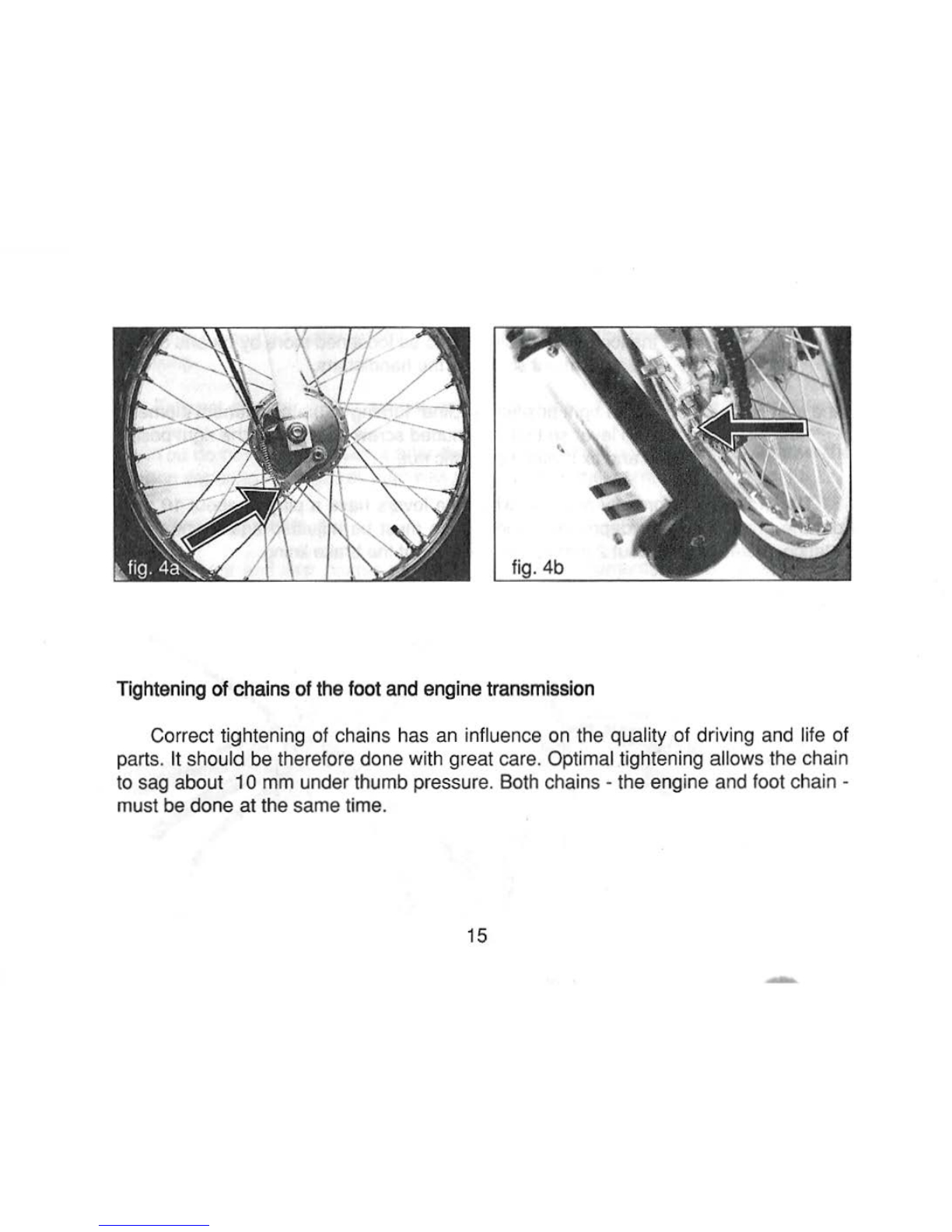
Tighte
ning
of
chains
of
th
efoot
and
eng
i
ne
tra
nsmi
ss
ion
Correct tightening
of
chains has an influence on the quality
of
driving and life
of
parts. It should be therefore done with great care. Optimal tightening allows the chain
to sag about
10
mm under thumb pressur
e.
Both chains -the engine and foot chain -
must be
done
at
the same time.
15 -
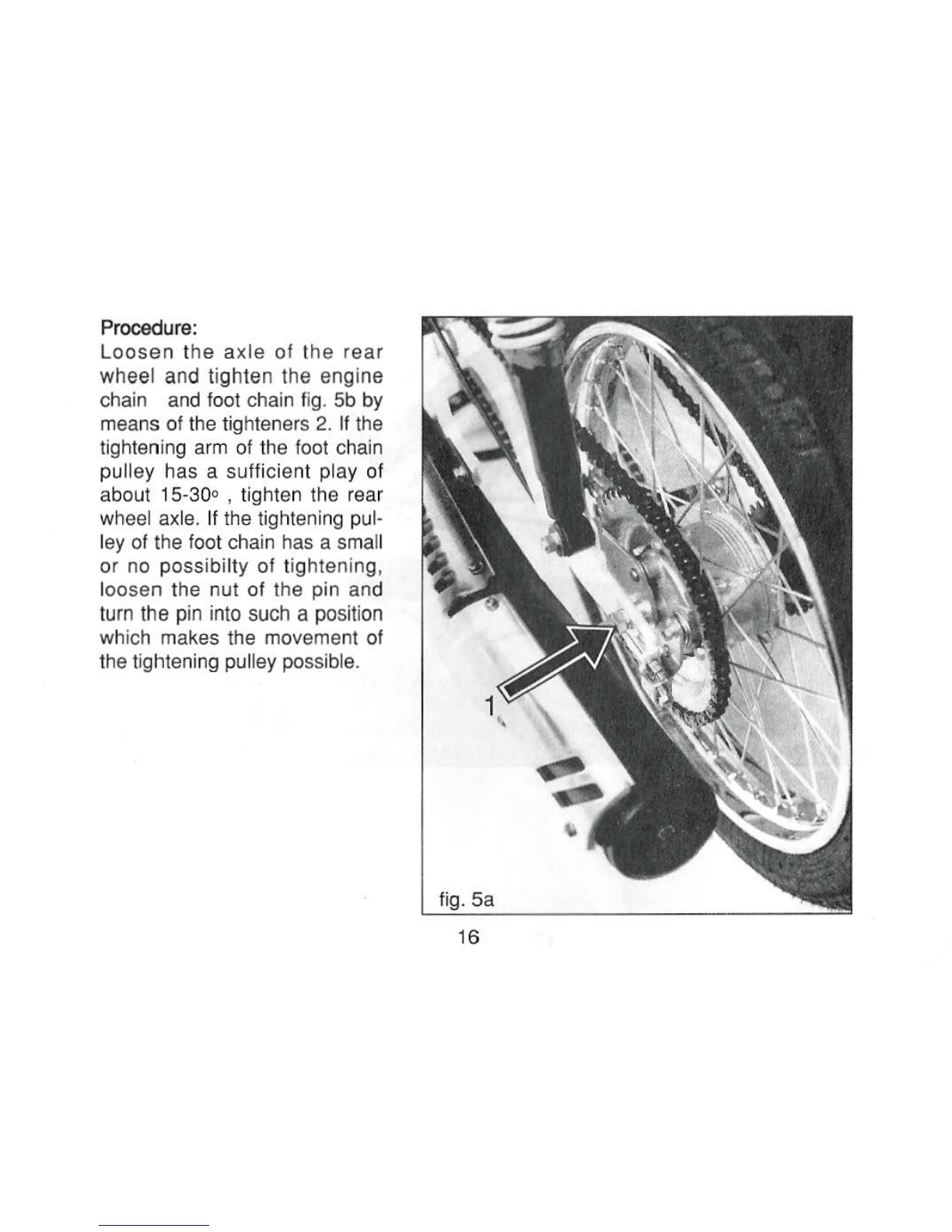
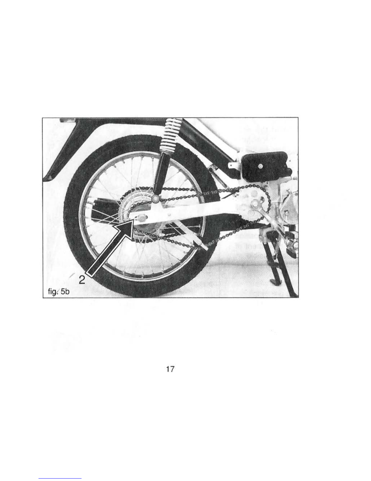
Procedure
:
Loosen
the axle of t
he
rear
wheel and tighten the engine
chain and foot chain fig.
5b
by
means of the tighteners
2.
If the
tighteni
ng
arm
of the foot chain
pulley has a sufficient play of
about 15-30o , tighten the
rear.
wh
ee
l axle. If the tightening pul-
ley of the foot chain has a small
or
no
possibilty of tightening,
loosen the nut of the pin
an
d
tu
rn
the pin into such a position
wh
ich makes t
he
movement of
the tightening pulley possible.
fig. 5a
16
17
Adjustment
of
the carburettor
The B
IN
G carburettor is adjusted by the manufacturer
to
give optimal parame-
ters. It
is
therefore undesirable to change the setting because it could.influence its
optimal setting.
If the carburettor
is
out of order it is recommended to have it repaired
in
an au-
thorized repair shop.
Oil change in gear-box:
Recommended oil
is
SHELL DONAX TA. Oil filling
is
done by producer for life
cycle of vehicle.
In
case of any other repairs where oil must be changed, contact your
dealer.
Adjustment
of
the ignition
Optimal ajdustment of t
he
ignition ensures optimal output of the engine. The ad-
justment has to be carri
ed
out with utmost care and accuracy and should be done
in
an authorized repair shop
18
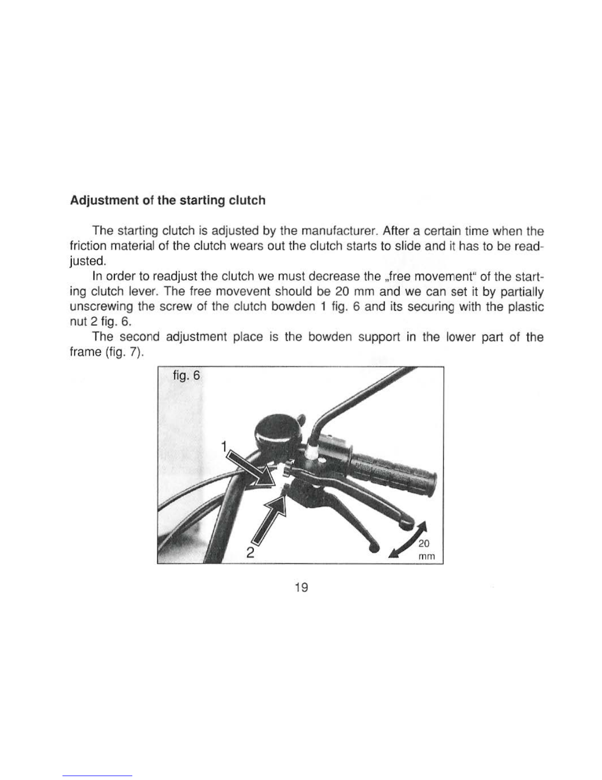
Adjustment of the starting clutch
The starting clutch is adjusted by the manufacturer. After a certain
ti
me
when the
friction material of the clutch wears out the clutch starts to slide and
it
has
to
be read-
justed.
In order to readjust the clutch we must decrease the ,free movement" of the sta
rt
-
ing clutch lever. The free movevent should be 20
mm
and we can set it by partially
unscrewing the screw of the clutch bowden 1 fig. 6 and its securing with the plastic
nut 2 fig. 6.
The second adjustment place is the bowden support
in
the
lo
wer part of the
frame (fig. 7).
fig. 6
19
Table of contents


