PSA Products Pinkerton User manual
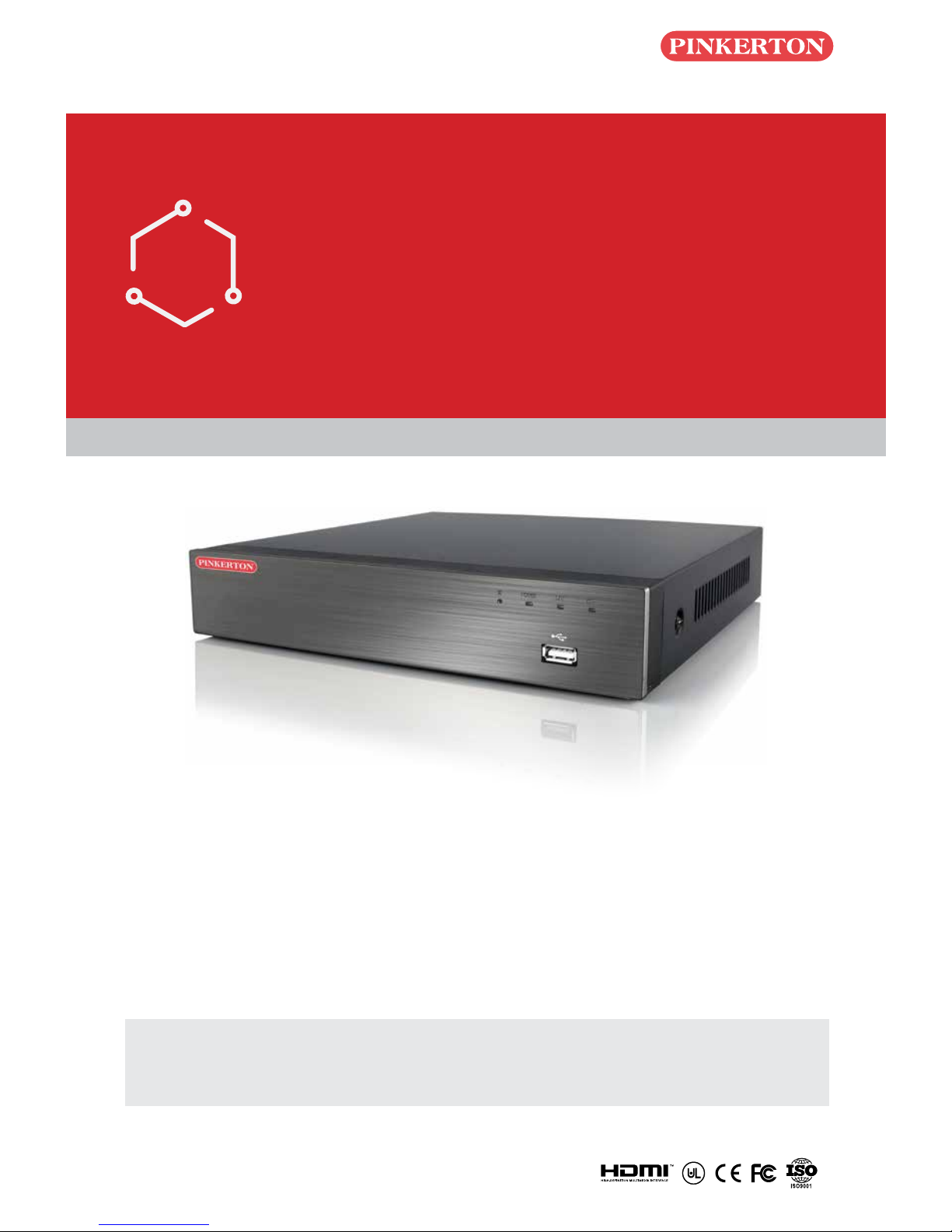
Quick Start Guide
Network DVR with H.264 Compression
DIY
Do-It-Yourself
IMPORTANT! This instruction guides you how to install surveillance system.
What accessories you need before getting started
1.One monitor or TV,can not be less than 19"
2.One VGA Cable/one HDMI Cable,use any one that monitor supports
3.One surge protector (advisable)
4.Power supplies for the DVR and cameras. Only use approved PSU's from your supplier.
5.Appropriate tools for installation.
Note:
This instruction is used to guide you install the system and remote surveillance, more instructions and
details can be downloaded from the CD,which come with DVR.
PINCCTVD80
Quick Start Guide
Network DVR with H.264 Compression
DIY
Do-It-Yourself
IMPORTANT! This instruction guides you how to install surveillance system.
What accessories you need before getting started
1.One monitor or TV,can not be less than 19"
2.One VGA Cable/one HDMI Cable,use any one that monitor supports
3.One surge protector (advisable)
4.Power supplies for the DVR and cameras. Only use approved PSU's from your supplier.
5.Appropriate tools for installation.
Note:
This instruction is used to guide you install the system and remote surveillance, more instructions and
details can be downloaded from the CD,which come with DVR.
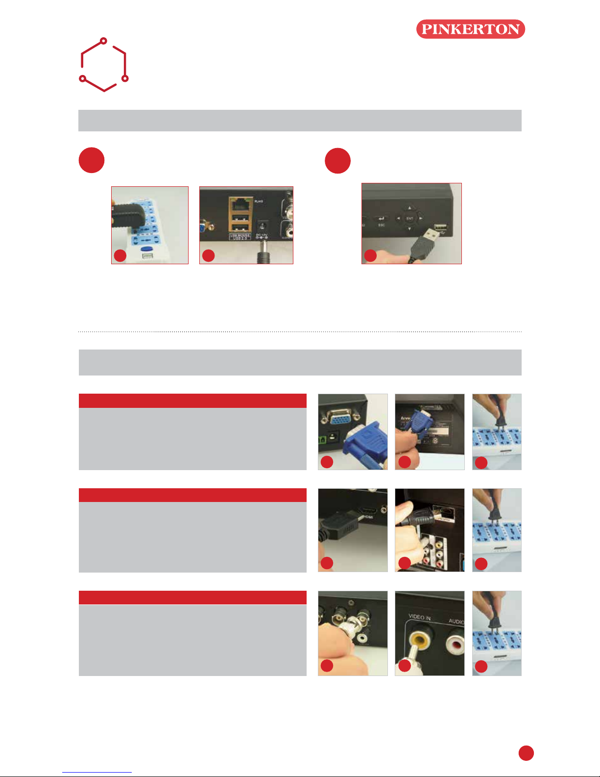
1
VIDEO
DISPLAY
Turning on DVR Connect Mouse
Using a high quality monitor, connect it to DVR via VGA Cable or HDMI Cable.
Connect DVR and surge protector using
power adaptor, like picture 1 and picture 2.
A
STEP
1
STEP
2
Connect Mouse to USB port on front
panel of DVR,like picture 3.
1 2 3
Monitor with VGA Port
STEP 1. Connect DVR and monitor using VGA Cable
STEP 2. Connect monitor plug on surge protector
STEP 3. Switch signal mode to VGA Input in monitor
menu
1 2 3
Monitor with HDMI Port
STEP 1. Connect DVR and monitor using HDMI Cable
STEP 2. Connect monitor plug on surge protector
STEP 3. Switch signal mode to HDMI Input in monitor
menu
1 2 3
TV with BNC Port (VIDEO IN)
STEP 1.Connect DVR and monitor using BNC-
RCA Cable
STEP 2.Connect monitor plug on surge protector
1 2 3
Note: You can choose one of the following three ways to connect DVR and monitor.
This way is only used among DVR and TV which
have BNC and RCA port
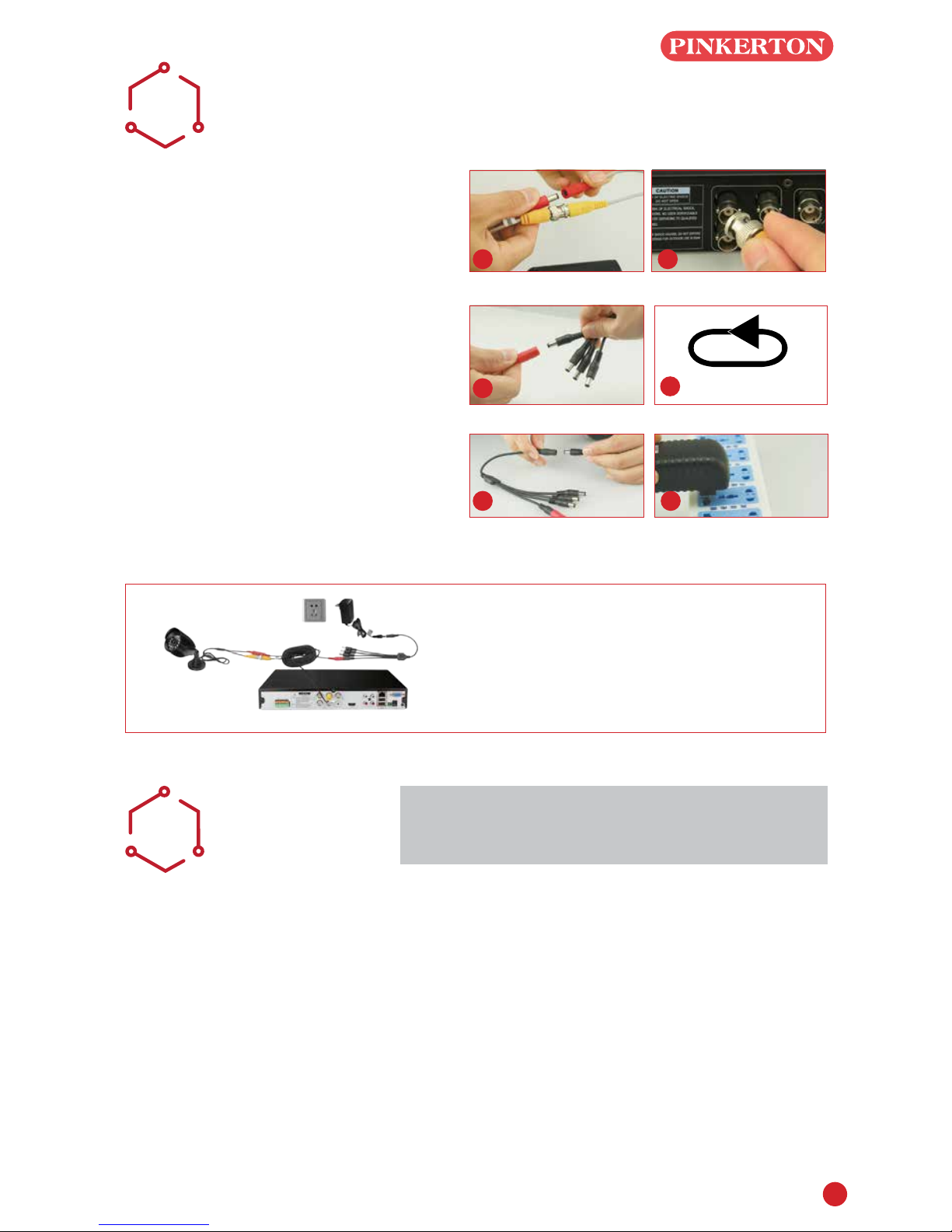
2
CAMERA
CONNECTING
B
STEP 1. Connect camera cable BNC
end(female) to extension cable
BNC end(male).
Note: Camera cable power end(male)
must connect extension cable power
end(female).
STEP 2. Connect the other extention cable
BNC end(male) to DVR Video in
connector(female).
STEP 3. Connect the other extention power
end(male) to power splitter cable
end(female).
STEP 4. Repeat above steps to connect
other cameras
STEP 5. Connect power splitter cable to
power adaptor
STEP 6. Plug your power adaptor to surge
protector or socket.
1 2
3REPEAT
You have nished mounting your system
4
5 6
CAMERA
PLACEMENT
CIt is important that the camera is positioned in
the correct location.
Cabling Distance Form DVR to Camera. The
video signal sent from the camera to the DVR is
reduced over distance. If you use a cable longer
than 30M then a CAT5 or RG59 cable should be
used (with suitable connectors).
The maximum distance allowed is 200M.
Do not install the camera close to high voltage
or other sources of electrical interference.
Install the camera in a position where it can not
be damaged or vandalised.
Avoid direct exposure to the weather. Cameras
which are weatherproof may be mounted outside
however the image will be affected by rain etc
landing on the lens. Do not allow direct sunlight to
land on the lens.
Indoor cameras. Do not expose to high levels of
humidity (steam/water vapour) or high levels of dust/
dirt.
Do not submerge any camera
Mounting. Ensure the camera is mounted on a
stable surface which is capable of supporting 5x the
weight of the camera.
Some CCTV kits have more than one power
supply unit. Simply repeat the above steps if
required.

3
Because your camera is weatherproof, it requires less protection than weather-resistant cameras and it can
be placed in more exposed locations if needed. Keep in mind that most cameras are designed to operate
between 14°F to 122°F (-10°C to 60C°) with a relative humidity of up to 95%) and consider wind chill and
other environmental factors when selecting your location.
Legal Considerations. Ensure it is allowed by your local laws
before installing cameras.
Do Not Install Camera Behind a Window. If there is a light source
behind the camera, it would cause a reection in the window that
will obscure events on the other side of the glass.Likewise, the
camera's infrared LEDs will reect off the glass and shine into
the lens, thus degrading the image.
WIZARD
SETTING
D
Before turning on DVR, ensure that all connections are good.
POWER ON AND LOGIN
Connect the power supply, DVR will power up.
The LED labelled POWER on the front will illuminate.
After DVR starts, a WIZARD SETTING pops
up.Time, network, record and hard disk management
can be set.
Click device name box to pop up a keyboad
as below:
It supports digits,alphabets and symbols.
Click Shift to input Capital letters and symbols; Click
Shift again to return.
Click Next to present a network setting window.
The default Http Port is 80, the default server port
is 6036. Click Obtain an IP address automatically
to acquire network information or input IP address,
Subnet mask,Gateway, Preferred or Alternate DNS
server manually. This function is used to monitor
DVR through internet(Refer to Remote Survellance
Guidance for details).
Click Next to present a Recording Setting window.
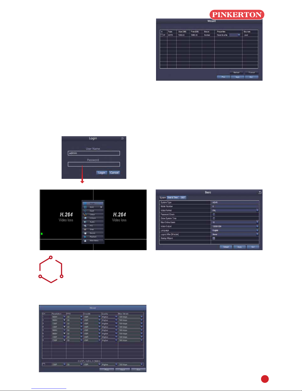
4
Select resolution, fps, encode, quality and bitrate.
When numeric value is higher, recorded video is
clearer, but more memory will be taken up.
Click Next to present HDD management window.
Check HDD information here, if it was installed
recently, select the HDD from the list to format it.
Click Next to present DVR status, click Finish button
to end Wizard.
You can refer to complete setup steps from the
relevant section of DVR User Manual. If you don't
want to setting Wizard, please click Exit.
If you wish to use both AHD and analogue cameras
on this DVR you will need to change the resolution
settings as follows:
Login
After exitting Wizard Setting, you can login to DVR.
Click shortcut menu button, a Login dialogue box is
presented
User Name: admin
Changing Display Resolution
Optimize DVR Video output to match with monitor
output as following steps:
Note:Make sure the monitor supports same
resolution as your DVR output resolution, otherwise,
the monitor is unable to display video.
STEP 1. Get into Main Menu from desktop shortcut
menu
STEP 2. Click Setup, then choose Basic menu
STEP 3. Select the desired resolution from Video
Output
STEP 4. Click Apply to save settings
STEP 5. Click Exit to restart system, and then re-
login afterwards
No Password
HD AND ANALOGUE
CAMERA SETTINGS
E
HD CAMERAS
SET TO 720P
ANALOGUE CAMERAS
SET TO 960H
THIS WILL SET CHANNELS IN PAIRS, i.e. (1 and
2)( 3 and 4)( 5 and 6 )( 7 and 8). You can not mix
the camera type in each pair.
Note: Above Setting is only applicable to Analogue
HD DVR

5
MOTION
F
Select Camera.Tick the Channel you want to
record on motion detection.
Holding Time. Set recording time length after
motion stop
Trigger. Multi-channels can be set to record
when detect the motion by one of cameras.For
example,when camera 1 detects motion,camera 2
and camera 3 can be triggered to record as well.
Area. It is allowed to set sensitivity area of camera
viewing range.
Click STAR to make the whole viewing range
as sensitivity area;
Click Trash Box to remove sensitivity area;
Click and drag mouse to draw or erase the sensitive
area.
As Color and luminance is important for sensitivity, so it's necessary to adjust its value at specic conditions.
The default value is 4 while value range is from 1 to 8.
Right click mouse to show or hide control menu at screen bottom.
Test the setting by moving something or some one walk through grid area within camera view range. If DVR
detects movement within grid area, a yellow hunanoid gure would be presented in the screen. The grid could
not cover ag, trees or some other ow objects in the wind to avoid false alerts.
Click to save setting Click to exit
PLAYBACK
G
Get into system Main Menu--Search, system
presents picture as following
Select the channel Start playing
Search the video you want via time or Event, then
play it.
Previous Record: Move to last recorded event
Next Record: Move to next recorded event
Fast Forward: video can be played at different speed,
from 1/4 times to 16 times.
Rewind: Video play can be rewinded at 1 time, 8 times,
16 times and 32 times.
Screen Display Mode: Both single-screen and
multi-screen are available. You can choose how many
channels you want to playback one time.Channel
without records presents blank screen.
Previous Record Next Record
Rewind
Fast
Forward
Play/Pause
Next frame
Previous
frame Single-screen
display
Multi-screen display
6
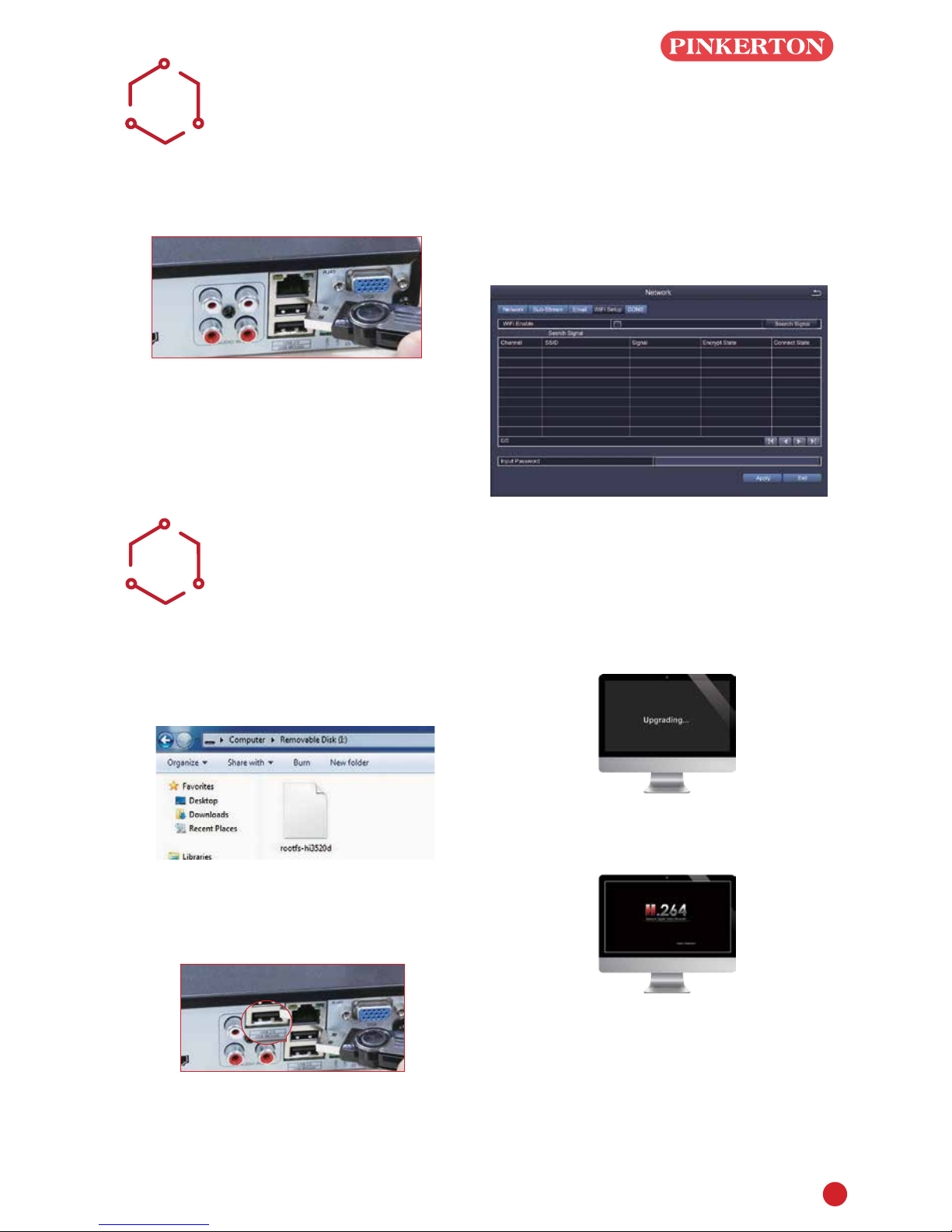
WIFI
H
Note: Only wireless dongle RT3070 can be
supported by the DVR.
STEP 1. Connect WIFI USB Dongle to USB2.0 port.
STEP 2. Select WIFI Setup, then click Search
Signal to choose a WIFI signal and input
corresponding WIFI password, click OK; When it
presents Connected, click Apply and Exit.
Note: It needs to connect the WIFI device again
after unplugging.
UPGRADE
I
If the DVR requires a software upgrade contact your
supplier. You will be sent the upgrade les by e-mail.
STEP 1 Put software into U-Disk, and ensure
software is at root directory as below
STEP 2 Put U-Disk into DVR port USB2.0.
Unplug the mouse from the front USB socket
STEP 3 Restart DVR(Power off and on), it will be
upgraded automatically.
Note: Plz wait for a few minutes until DVR
interface presents.
7
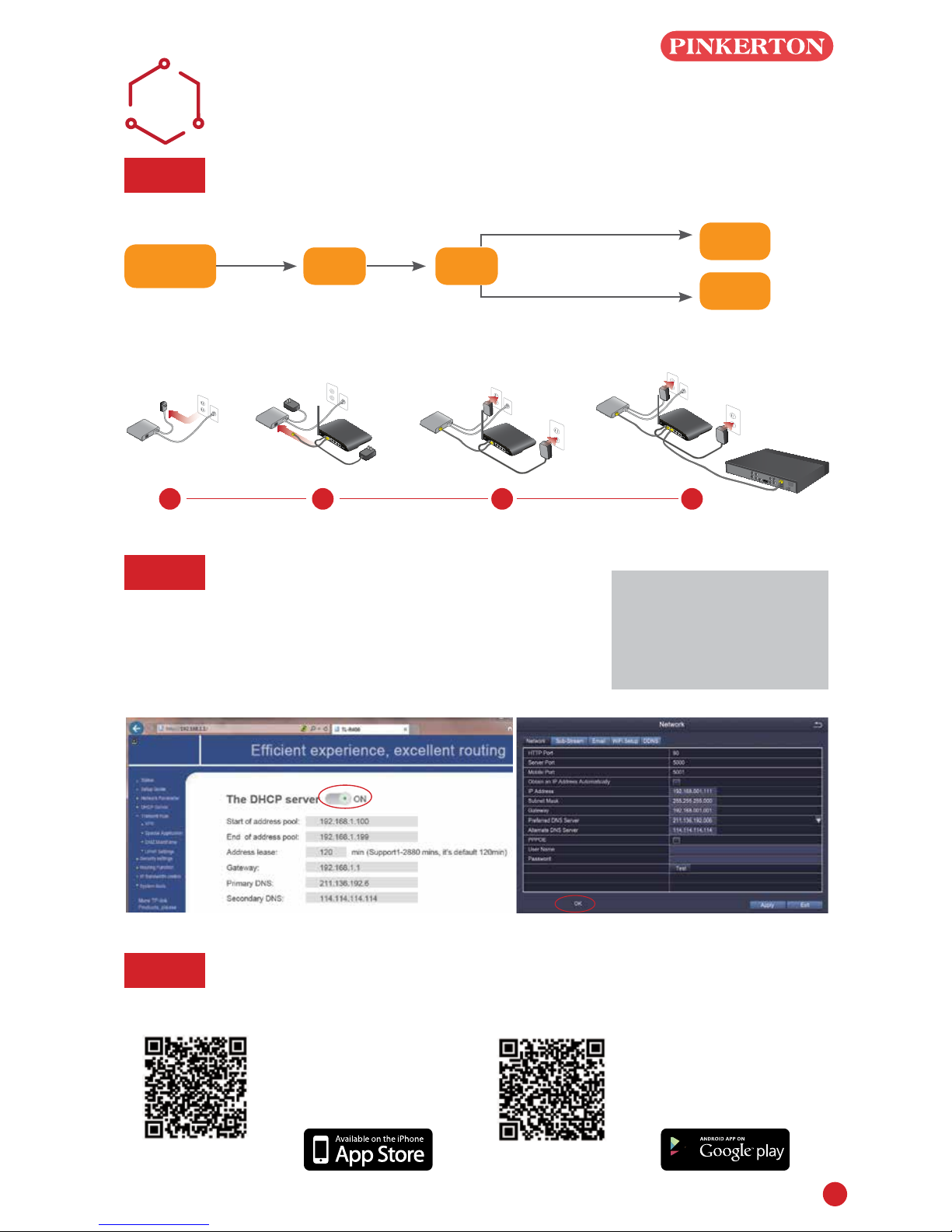
REMOTE SURVEILLANCE
GUIDE
J
Step 1. How to connect DVR to LAN ?
Schematic Diagram
Unplug modem then connect router and device
Fibre Optic DSL Router
DVR/NVR
PC
RJ45 cable
WIFI or RJ45 Cable
DSL/CABLE
MODEM
DSL/CABLE
MODEM
DSL/CABLE
MODEM
DSL/CABLE
MODEM
ROUTER ROUTER
ROUTER
DVR
1 2 3 4
Note: Before monitoring
via smartphone or
computer, please
ensure your DVR can be
connected to internet.
Step 2. How to test your DVR's network ?
(1) Right click Mouse - Main menu - Set up - Network
(2) Tick 'Obtain IP address automatically'
(3) Click Test, if 'OK' is displayed, the network is connected successfully.
Note: Please ensure DHCP in your router is open
Step 3. Remote Monitoring Setting
A: Smartphone Remote Monitoring
(1) iPhone/iPad User:
Search 365SECU in app
store and install it, or scan
the following QR code to
download 365SECU
Appstore QR code Android QR code
(2) Android User: Search
365SECU in google play
and install it, or scan the
following QR code to download
365SECU
8
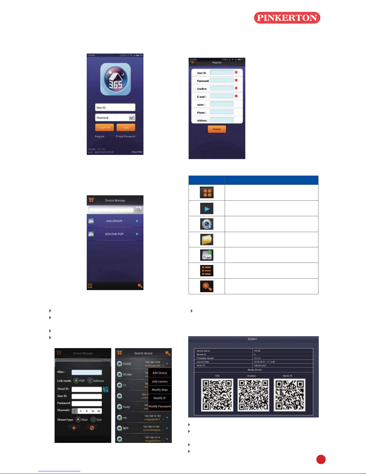
(3) Login Interface instructions
Start 365SECU as following
(4) User Registration
The new user need to get an account from the login
interface. Click button 'Register' and ll information
as following
(5). Device Management Instruction
Main menu –Device Manage
These items must be
completed
User ID: User name during
login
Password: Login
password (at least 6 digit)
Conrm: Repeat the
password
E-mail: Used to send
password reminders
Name: Optional item
Phone: Optional item
Address: Location of DVR
Alias: Device name
Link mode: Two different link mode, P2P and
address
P2P: Connect network via seria ID
Address: Connect network via IP address/DDNS
Cloud ID: Serial ID in DVR, which can be
obtained in DVR system menu(Main menu-
Information-System-Serial ID). This can be input
using the QR code scanning option.
User ID: admin (Defaulted, same as DVR user ID)
Password: Null (Defaulted, same as DVR system
password)
Channel: DVR channel
Stream Type: Resolution: D1 Resolution: CIF
icons Instruction
Return to main menu
Click to pop up the item to modify the
parameter, name, etc.
Camera
Catalogue
Device(DVR)
Pop up items to add Directory, DVR,
camera.
Search Local Device(DVR)

9
B: PC Client Remote Monitoring
Download 365SECU from CD, install and start it as
below picture
Account: same as the 365SECU account in
smartphone
Password: same as the 365SECU account in
smartphone
Enter main interface, and show it as following
Remark: The PC operation has the same 'create'
& 'Delete' function as the Smartphone
365SECU
C: IE browser Remote Monitoring
(1) When testing the network 'OK'(Step 2),you
can get an IP link like http://192.168.1.111,
input the link in IE browser and open it
(2) When visit(live view)your DVR at the 1st
time, the IE browser settings should be,
IE-Tools-Internet Options-Security-Internet-
Customization level
Tick all Enable in options, and click OK to save.
After nishing download ActiveX controls, pop up
login.
Note: If the surveillance preview does not work with
the above settings, change the IP Address to
'Fixed' as follows
Note: Check with your I.T manager before making
these changes
1. Open the router
2.Find the router Subnet Mask(for example:
255.255.255.0), Preferred(Primary)DNS server (for
example: 211.136.192.6), Altermate(Secondary)
DNS Server(for example: 114.114.114.114)
3.Input Subnet Mask, Preferred DNS Server and
Altermate DNS Server in DVR menu accordingly,
DVR system menu path is : Main menu – Set up
- Network
Note:1.Please ensure the IP address you input
is not used by any other device, such as,
computer, server, etc.
2.Please ensure Subnet Mask,DNS Server
in DVR menu and Router System menu are
same.
3.The system menu in different routers are
different. But Subnet Mask, Preferred DNS
Server, Altermate DNS Server can be found in
all Router.
Click Test, if ‘OK’ is displayed, the network is
connected successfully.

Warranty & Liability
1 PSA Products Pty Ltd (ABN: 99 076 468 703) of 17 Millicent Street, Burwood 3125 Victoria,
Australia warrants this product for a period of 12 months from the date of purchase, as
reflected on the Authorised Reseller’s or Distributor’s invoice / receipt provided to you. PSA
Products Pty Ltd will repair or replace the product (at the option of PSA Products) due to
any manufacturing defect, at the cost of PSA Products Pty Ltd (excluding any labour costs
relating to removal or re-installation of product, and transport costs).
2 This warranty shall not apply to the product if it has been damaged, modified, abused or
altered after the date of purchase, or if it fails to operate due to improper maintenance.
3 To the extent permitted by law, the liability of PSA Products Pty Ltd arising from the sale or
under the terms of this limited warranty shall not in any case exceed the cost of replacement
and subject to this clause. In no case shall PSA Products Pty Ltd be liable for consequential
loss or damages resulting from the failure of the product or breach of this, or: Any other
warranty, express or implied, loss or damage caused by failure to abide by the instructions
supplied in the leaflets.
4 To the extent permitted by law, PSA Products Pty Ltd., makes no warranty, expressed or
implied, written or oral, including that of merchantability or fitness for any particular purpose,
with respect to the consumer replaceable battery if any. A product with non-serviceable
built-in battery is covered under warranty of the product as per point 1.
5 This warranty is provided in addition to other rights and remedies you have under law: Our
goods come with guarantees that cannot be excluded under the Australian Consumer Law.
You are entitled to a replacement or refund for a major failure and compensation for any other
reasonably foreseeable loss or damage. You are also entitled to have the goods repaired or
replaced if the goods fail to be of acceptable quality and the failure does not amount to a
major failure. What constitutes a major failure is set out in the Australian Consumer Law.
6 To make a claim under warranty, take the product (with a proof of purchase) to the store
where you purchased the product or contact PSA Products Pty Ltd. Phone (03) 9888 9889.
writing.
Table of contents
Other PSA Products DVR manuals

Popular DVR manuals by other brands


Summit Systems
Summit Systems DIGITAL VIDEO RECORDER Operation manual

Swann
Swann SW242-SR4 user manual

Digimerge
Digimerge DH100 Series instruction manual

Panasonic
Panasonic WJHD220 - DIGITAL DISK RECORDER operating instructions

Eneo
Eneo DLR1.1-04N/250V operating instructions

Whistler
Whistler D2200S user guide