LAFI-SA IVE-1004D-1008C-1016C User manual

- 1 -
Real time Digital Video recorder
DIGITIAL VIDEO RECORDER
(4/8 channel)
USER’S MANUAL
RoHS
IRIS-U
IVE-1004D/1008C/1016C
USER'S MANUAL
WWW.LAFI-SA.COM
IVE-1004D-1008C-1016C
USER'S MANUAL

Important Safety Instructions.
zRead and Keep these instructions
zHeed all warnings
zFollow all the instructions
zDo not use this apparatus near water and Clean only with dry cloth
zDo not install near any heat sources such as radiators, heat registers, or other apparatus that
produce heat
zProtect the power cord from being walked on or pinched particularly at plugs, convenience
receptacles, and the point where they exit from the apparatus.
zUnplug this apparatus. When a cart is used, use caution when moving the cart/apparatus
combination to avoid injury from tip-over.
TO REDUCE THE RISK OF ELECTRIC SHOCK, DO NOT REMOVE.
NO USER-SERVICEABLE PARTS ARE INSIDE. REFER SERVICING TO QUALIFIED SERVICE PERSONNEL.
.
FCC For Class A digital device
A CLASS A digital device that complies with Parts 15 of the FCC Rules.
Operation is subject to the following two conditions.
1. This device may not cause harmful interference, and
2. This device must accept any interference received,
Including interference that may cause undesired operations.
The lightning flash with an arrowhead symbol within an equilateral triangle is
intended to alert the user to the presence of uninsulated “ dangerous voltage” within
the product’s enclosure that may be of sufficient magnitude to constitute a risk of
electric shock to persons.
The exclamation point within an equilateral triangle is intended to alert the user to
presence of important operating and maintenance (Servicing) instructions in the
literature accompanying the appliance

- 2 -
CONTENTS
1. Product Overview
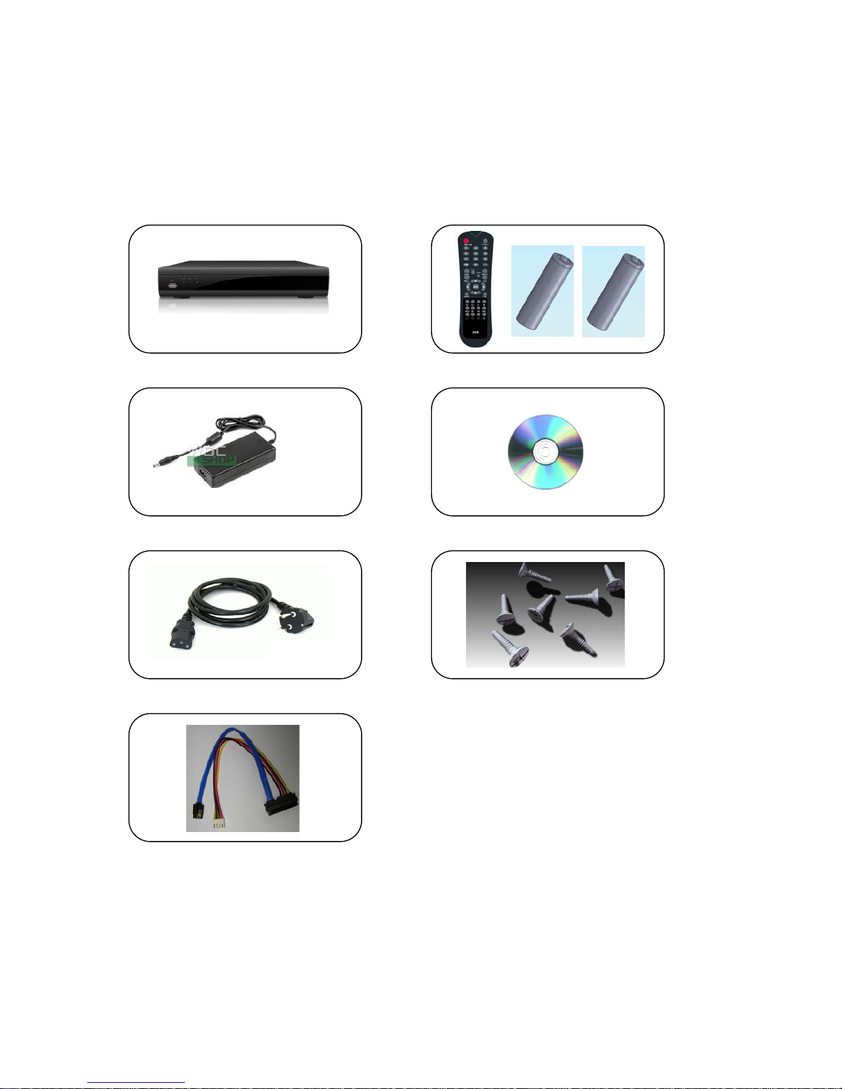
1.1 Packing Contents ··············································································· 5
1.2 Front ··············································································· 6
1.3 Rear ················································································ 6
1.4 Remote Controller ················································································ 7
2. Installing Product
2.1 Installing HDD ················································································· 9
2.2 Connecting Camera and Audio Device ························································· 9
2.3 Connecting Monitor ·············································································· 10
2.4 Connecting Optional Device ····································································· 10
2.5 Connecting Network ················································································ 10
2.6 Connecting Power Supply ········································································ 10
3. Operation
3.1 Turning On ·························································································· 12
3.2 Initial Screen ······················································································· 12
3.3 Screen Layout ························································································ 12
3.4 Other Functions of Remote Controller ··························································· 15
3.5 Mouse ································································································· 16
3.6 Mobile Viewer ······················································································· 17
4. MENU
4.1 How to display Menu window ····································································· 20
4.2 Setup Menu ·························································································· 21
4.2.1 Display ·························································································· 21
4.2.2 Camera ························································································· 22
4.2.3 Record ·························································································· 25
4.2.4 Event ·························································································· 27
4.2.5 Storage ························································································ 31
4.2.6 Network ························································································ 31

- 3 -
4.2.7 System ·························································································· 36
4.3 Search ························································································ 40
4.3.1 Search by Time ················································································ 41
4.3.2 Search by Calendar ·········································································· 41
4.3.3 Search by Event ··············································································· 41
4.3.4 Go to First ················································································ 42
4.3.5 Go to Last ················································································ 42
4.3.6 Search mode ················································································ 42
4.4 Function ························································································· 43
4.4.1 PTZ ························································································· 43
4.4.2 Audio ························································································ 43
4.4.3 Backup ························································································· 44
4.4.4 Log View ························································································· 44
4.5 OSD OFF ···························································································· 45
4.6 REC ····························································································· 45
4.7 Log Out Control ·················································································· 45
5 Specification ············································································ 46
Troubleshooting ············································································· 47

- 4 -
1. Product Overview

- 5 -
1.1 Packing Contents
Once opening the product box, please check out whether there are all contents as follows
and there are some visible damages. If any of these items is missing or damaged, contact your
supplier immediately before using the product.
DVR product Remote control &Battery
Poweradaptor Software /User’sManual CD
Powercable HDDScrews
HDD Cable [Included in Set]

- 6 -
1. 2 Front
1. USB PORT USB device(mouse, memory stick, HDD) can be
connected
2. LED LED indicators that show power, recording & network
status
1.3 REAR
1. DC 12V POWER Connect Power Adaptor included in Box
2. ETHERNET 10/100MB LAN port
3. USB PORT USB Devices(mouse, memory stick, HDD) can be
connected
4.
485 PORT 485 port has +, and – terminals
GROUND G for Ground used for earth
ALARM A for Alarm, which signal occurs
SIGNAL S for Signal
5. SPOT OUT Connect analog TV monitor for spot (Composite)
6. VGA OUT Connect VGA monitor
7. AUDIO IN/OUT One channel Audio IN/OUT
8. VIDEO IN VIDEO INPUT PORTS for 4 Channels
9. VIDEO IN VIDEO INPUT PORTS for 8 Channels
10. IR Connect IR extension cable
12345678910
1 2

- 7 -
1.4 Remote controller
1) REC : Record button
2) DVR-ID
3) Number button
4) AUDIO : Audio ON / Mute
5) BACKUP :
Back up recorded data to other device
6) MENU :
Go to ‘MENU’ mode to setup values
7) OSD : Show or Hide OSD
8) PTZ : Control Pan/Tilt/Zoom camera.
9) Digital Zoom
10) Direction (▲,▼,◀,▶)
Move cursor or control PTZF camera
ENTER
Select sub item in system setup mode
11) SEARCH : Search recorded video
12) LOG : Show running status of DVR system
13) ◀◀ : Reverse play
14) ▶I : Play or Pause during playback
15) ▶▶ : Fast forward play
16) ■: Stop playback and go to Live mode
17) SPOT : Not Operated in this model
18) PIP : Go to PIP mode
19) POP : Enlarge specific channel in Live mode
20) SEQ : Show each camera rotation
21) Full screen mode
22) Quad screen mode
23) 9 Division screen mode
Operated only for 8ch or 16 channels
24) 16 Division screen mode
Operated only for 16 channels
1
3
4
76
8
10
11
9
13
12
14
17
22
19 16
15
2
5
21 23
24
18 20

- 8 -
2. Installing Product

- 9 -
2.1 Installing HDD
1 HDD can be installed inside the product and install HDD before you start the product.
Be careful not to be harmed by sharp edges of the product.
(1) Loosen screws on the back to detach the
top cover.
(2) Lift the end of top cover and pull out
from product.
(3) To install HDD, you should upside down
the set, and HDD can be installed onto
bottom with screw.
(4) Connect HDD Power and cable to HDD.
(5) Insert top cover to product as side
picture and tighten screws again.
2.2 Connecting camera and audio device
Connect video signal cable (BNC type) into VIDEO IN port on rear of the product.
Connect RCA cable from microphone into AUDIO IN port on rear of the product.
Connect RCA cable into AUDIO OUT port on rear of the product and into audio device.
Audio OUT
Audio IN
Camera input
2 1

- 10 -
2.3 Connecting monitor
Connect spot and VGA port in DVR to monitor
2.4. Connecting Optional device
You can connect and control the PTZ device supporting RS-485 communication.
2.5 Connecting Network
Connect LAN cable (RJ45) to Ethernet port on rear of the product.
2.6 Connecting power supply
Connect provided power cable to AC-DC adaptor.
Connect the adaptor to DC power port on rear of the product.
Connect AC power plug to the plug socket.
LAN cable (RJ45)
INTERNET
VGA
Spot (BNC)

- 11 -
3. Operation

- 12 -
PLEASE REMIND THAT THE HDD SHALL BE INSTALLED AT FIRST BEFORE USING DVR.
3.1 Turn on
zPlease connect Power Adaptor included in Box into power DC terminal.
There is no separate power switch, so The DVR shall turn on automatically as soon as it is
connected.
3.2 INITIAL SCREEN
The below screen will be shown after booting is over.
Please move the pointer into password window with mouse or up/down key of
remote controller, and then press enter button in remoter controller or right
button of mouse. The below enter password window will be shown, and you input
“0000” 4 digits. The default password is “0000” 4 digit. After input “0000”, the
Log-in window will be shown again. Select LOGIN icon, and you can start to use
DVRs
3.3 Screen Layout
You can see the below items according to your selection on function.

- 13 -
3.3.1 Icons in Live Display Mode
In Live display mode, icons will be indicated on the screen to notify the system mode or status.
Below are the icon categories, which are indicated on the monitor.
Icon to be shown
at right-upper corner on each channel
Icon to be shown
at left-bottom corner on full screen.
Selects specific 1ch with full screen When Motion Detected
Screen-Division mode When Sensor Activated
HDD capacity usage status PTZ
When USB memory stick & HDD Recording
When DVR is accessed via network
When ID of remote control is set
Icon to be shown in 1ch full screen mode
Channel sequence mode
Digital x2 Zoom
3.3.2. Playback Buttons
If you select search mode, the status will be shown in the upper side of screen.
Now status
-This rectangular show the now status of playback.
-If you select ▶, the mark will be changed to ▶,
-And the mark will show ▶▶, when ▶▶ is selected
◀◀ Backward - Control backward speed.
- Move frame by frame reversely in pause mode
▶Play/Pause - Play or Pause the video
▶▶ Fast Forward - Control forward speed.
- Move frame by frame forwardly in pause mode
■Stop Stop the playback and go to Live mode
Menu button also stop playing.
Quick Search - If you click this Icon, the Search sub-menu will pop up

- 14 -
Play speed -◀◀ / ▶▶ x8, x32, x128 supported
How to use Playback bar
- Play starts with PLAY button.
If you press PLAY button in LIVE mode, or select one thing in SEARCH SUB-MENU, DVR will prepare
to play the recording data from the point you selected
- Playback mode changing
To display different screen mode, click the Monitor Icon on screen and select different mode.
You can control playback speed with ◀◀ / ▶▶ button. Click ◀◀ / ▶▶ button once then it will
be x8, twice will be x32 then 3 times click is x128.
After clicking ■(stop button) , message will pop up in case of clicking by mistake.
3.3.3. Other Icons
3.3.3.1 HDD STATUS
It indicatescapacityofHDD, the percentage show the usage of HDD.
3.3.3.2. SCREEN SHOW STATUS
You can select how screen will display.
In Live MODE, there are 5 modes : PIP, POP, Sequence, Quad, 9
But the 9 cannot operate in 4 channels.
In play mode, there are 2 modes : Quad, 9,
Also, only quad mode can be operated in 4 channels.
3.3.3.3. CHANNEL ICON
You can change channel displays on screen. There are 1~4 in 4ch product, and 1~8 in 8ch.
3.3.3.4. USB ICON
This Icon will be shown after you attach USB into DVR,
3.3.3.5. NETWORK ICON
This Icon will be shown while someone access DVR through Network with CMS, or Web-viewer.
3.3.3.6. Remote controller ID Icon
This Icon will be shown if you set up system ID in system sub-menu.
The color of number of Remote control Icon will be changed to “Yellow” in case that status is
active, that is the number of remote controller matches the number of system ID.
Otherwise, the color will be changed to “RED”.
IfyouclickRemotecontrol ID Icon, you can see the below;
Status =Active[orDe-active]

- 15 -
SYSEM-ID = 01, Request-ID = 01
Status meansthatthe DVRcanbe operated or not with the remote controller.
SYSTEM-ID means the number of remote controller ID of DVR.
Request –ID means that the number of Remote controller you have got.
If you like to control the DVR with the remote controller, the value of SYSTEM _ID is the same to
that of Request-ID.
NOTE : You should press two digits when you select System-ID. For example, press 0 + 5, when you
select 05. Don’t press only 5. (Please refer to page34 for setting remote control)
3.4. Other function of Remote control
3.4.1. Full screen mode
- Press button. Whenever pressing button, screen will go to next screen.
- Press desired numeric button of remote controller.
3.4.2. Quad screen mode
- To see quad screen mode, press button.
-Whenever pressing button, screens will go to next quad screens.
- If you press a numeric key of remote controller which is inside current display range,
selected channel is displayed as full screen mode.
- If you press a numeric key of remote controller which is outside of current display range, the
quad containing selected numeric will be displayed.
E.g. you press 6 while current screen shows CH1~Ch4, CH5~CH8 will be displayed.
3.4.3. 9ch display mode – Only for 8 channel DVR
- To see cameras by 9ch mode, press button.
3.4.4. POP mode : Only for 8 channel
- Press POP button to enlarge specific camera with 7 other cameras.
- Whenever pressing POP button, the biggest screen will change.
3.4.5. OSD Hide or Show
- Press OSD button of remote controller to appear or disappear OSD.
- You can set to hide Status bar only at SETUP menu [SETUP ÆDISPLAY ÆOSD]
ÆWhen there is no command into DVR, Status bar will be hidden.
When you press any button or click by mouse, Status bar will be shown again.
1 CAM01 2 CAM02
3 CAM03 4 CAM04
5 CAM05 6 CAM07
7 CAM07 8 CAM08
6

- 16 -
3.4.6. PIP mode (picture in picture)
In case of full screen display mode, you can see other camera with a small window.
(1) Press PIP button of remote controller.
(2) If you press PIP button again in PIP mode, the position of two screens will change each other.
(3) Press numeric button of remote controller in PIP mode to change small screen to desired
screen.
E. g.)
(4) Press Direction button or drag by mouse to move small screen to desired position.
3.4.7. Sequence mode
- If you press SEQ button in case of FULL or QUAD screen mode, screen(s) will rotate
automatically.
- Default value of cannel changing interval is 2 or 3 seconds.
- User can select changing interval value from 1 to 99 seconds.
- User can select desired channel to display
3.4.8. Digital-ZOOM
If you press ZOOM key of remote controller while in full screen mode, Digital-ZOOM
function will work.
If you press direct button of remote controller, Zoom-Area window will move.
If you press ZOOM key again, Zoom-Area window will be enlarged or diminished.
If you press ENTER key, selected Zoom-Area will be displayed as full screen.
3.5. MOUSE
zSystem supports USB MOUSE
zJust connect USB mouse, then DVR will detect it automatically.
1
2
‘PIP’ Button 2
1
1
2
Cam ‘3’ Button 1
3

- 17 -
zSome kinds of USB mouse may not be compatible with product.
3.5.1 Change screen mode
Left button of mouse is for selecting an item. Right button of mouse is usually for canceling
menu table or going to former menu mode. Additionally, if you press right button of mouse
on basic screen, following window will appear.
zIf you double-click left button on a specific channel, the screen changes into full screen mode.
With double-click again, screen will go back to previous mode.
zAt PIP mode, if you want change channel of small window, click right button of mouse. Then,
screen mode menu will appear. Click desired channel button.
3.5.2 Pop the windows to input the values
In the Menu status, right button of mouse is used for pop the windows to input numbers or
characters in windows
3.6. Mobile Viewer
3.6.1. Mobile Viewing Method through web-browsing
Once your phone can access internet, you can see the screen through 3G Mobile phones.
The transmitted picture is Jpeg file, so you don’t need special application to operate this function.
When DVR is connected to Internet or LAN, it has its own IP address.
If you open internet browser, please write down http:// DVR IP address/mobile.html.
If you use other web-port except 0080, you should add port number as
http:// DVR IP address:port number/mobile.html. Please see network parts to get more information.
If there is no problem with the address, you can see the windows as below.
Please input USER ID & PASSWORD then you will see Jpeg control box. Select channel, size and delay.
Then click start button.
Channel – Select channel you want.
Size – Select video resolution you want. There are two kinds: 352x240/176x120
NOTE If recording resolution of DVR is set as 720*480, you can not see video at 176*120 resolution
in mobile phone. So, you should set up the recording resolution in DVR under 720*480 so
that you can see the video at 176*120 resolution in mobile.
Delay – The picture refreshed time, the unit is second : real time, 0.5, 1, 2, 5
If you select 2, the frame is refreshed every 2 seconds.

- 18 -
3.6.2. Mobile viewing method through mobile-viewer application on smartphones.
This mobile viewing method is using our own mobile viewer software through smart phones such as
iPhone, Android, Symbian and blackberry and you can get much more frames than above browsing
method. You can download our mobile application and currently we support iPhone and Android base.
< iPhone users>: our mobile viewer is ‘Proeye’ so you can search and download ‘Proeye’ in app store.
<Android users>: our mobile viewer is ‘Proeye’, you can search and download ‘Proeye’ in google app.
For details of how to use “Proeye”, please check the manual of CD provided when you purchased DVR or
contact your provider.

- 19 -
4. MENU
Table of contents