PSP 285 User manual


Acknowledgements
Main plug-in development and algorithms: Piotr Dmuchowski
Additional algorithms and algorithm assistant: Mateusz Woźniak
Project Development: Piotr Dmuchowski
Plug-in Design and Graphics: Mateusz Woźniak, Piotr Dmuchowski
Platform: Adam Taborowski
Installer: Piotr Dmuchowski
Product Manager: Antoni Ożyński
Documentation: Mateusz Woźniak, Piotr Dmuchowski, Mike Metlay
Alpha testing: Alberto Rizzo Schettino, Maciej Polański, Whyman Baker, Joachim Krukowski.
Beta testing: Alberto Rizzo Schettino, Maciej Polański, Whyman Baker, Joachim Krukowski,
Count Eldridge, Cameron Gorham, Joanna Stefańska, Maja Szydłowska, Mike Metlay.
Presets designed by:
•Cameron Gorham aka Venus Theory,
•Count Eldridge,
•Joanna Stefańska,
•Maja Szydłowska,
•Steve Marcantonio,
•Whyman Baker,
•PSP Team.
Special thanks to Whyman Baker and Maciej Polański for many useful ideas, comments,
suggestions and deep involvement in the alpha stage.
Thanks to all our users around the world for ideas and help in the development of new plug-ins!
By using this software you agree to the terms of any license agreement accompanying it. “PSP”,
the PSP logo, “PSP 285”, "PSP 85", PSP 84"and “It’s the sound that counts!” are trademarks of
PSPaudioware.com s.c.
All other trademarks are the property of their respective owners.
© 2022 PSPaudioware.com s.c.

Table of Contents
ACKNOWLEDGEMENTS..................................................................................................................................2
END USER LICENSE AGREEMENT................................................................................................................4
OVERVIEW............................................................................................................................................................5
FEATURES.......................................................................................................................................................................5
APPLICATIONS...............................................................................................................................................................6
ARCHITECTURE: HOW PSP 285 WORKS..................................................................................................7
VARIABLE SAMPLE RATE DELAY LINES.......................................................................................................................7
HIGH QUALITY REALTIME SAMPLE RATE CONVERSION.........................................................................................8
FILTERS...........................................................................................................................................................................9
MODULATION............................................................................................................................................................11
REVERBERATOR..........................................................................................................................................................12
MASTER SECTION......................................................................................................................................................12
GATE.............................................................................................................................................................................13
DUCKER.......................................................................................................................................................................13
PSP 285 BLOCK DIAGRAMS..................................................................................................................................14
USER INTERFACE: HOW TO USE PSP 285...............................................................................................15
MAIN SECTION...........................................................................................................................................................15
MIXER SECTION.........................................................................................................................................................15
DYNAMICS SECTION..................................................................................................................................................16
DELAY SECTION..........................................................................................................................................................17
DELAY CONTROL SECTION......................................................................................................................................20
MODULATION (LFO & ENV) SECTION................................................................................................................21
Low Frequency Oscillator................................................................................................................................. 21
Envelope Follower............................................................................................................................................... 21
MANUAL TEMPO CONTROL....................................................................................................................................22
FILTERS SECTION........................................................................................................................................................23
Filter 1:................................................................................................................................................................... 23
Filter 2:................................................................................................................................................................... 23
DRIVE section...................................................................................................................................................... 24
REVERB SECTION.......................................................................................................................................................25
PRESET HANDLING AND VIEW OPTIONS.............................................................................................26
PRESET BROWSER.....................................................................................................................................................27
COPY / PASTE.............................................................................................................................................................28
A/B SYSTEM...............................................................................................................................................................28
UNDO / REDO............................................................................................................................................................28
GUI RESIZING.............................................................................................................................................................28
CONFIG SECTION.......................................................................................................................................................29
MINIMUM SYSTEM REQUIREMENTS......................................................................................................30
PROCESSING......................................................................................................................................................31
LIMITATIONS OF THE DEMO VERSION..................................................................................................31
SUPPORT.............................................................................................................................................................32

End User License Agreement
PREFACE: This End-User License Agreement (“EULA”) is a legal agreement between you and
PSPaudioware.com s.c. (PSP) for the PSP product accompanying this EULA, which includes
computer software and may include associated media, printed materials, and “online” or
electronic documentation (“SOFTWARE”). By installing, copying, or using the SOFTWARE, you
agree to be bound by the terms of this EULA. If you do not agree to the terms of this EULA, you
may not use the SOFTWARE. The SOFTWARE is protected by copyright laws and international
copyright treaties, as well as other intellectual property laws and treaties. The SOFTWARE is
licensed, not sold.
LICENSE: You can INSTALL and USE the current version of the SOFTWARE, or in its place any
prior version, on three computers simultaneously so long as you are the direct user or a studio
client of those machines. If more users USE the software you must buy an additional license for
each workstation. The DEMO VERSION of the SOFTWARE is NOT LICENSED FOR
COMMERCIAL USE.
RESTRICTIONS: You may not transfer, modify, rent, lease, loan, resell, distribute, network,
electronically transmit or merge the SOFTWARE. You may not reverse engineer, decompile or
disassemble the SOFTWARE, or otherwise attempt to discover the SOFTWARE source code.
You are not permitted to copy the SOFTWARE or any of the accompanying documentation.
COPYRIGHTS: All title and copyrights in and to the SOFTWARE (including but not limited to
any images, photographs, animations, video, audio, music, text, and “applets” incorporated into
the SOFTWARE ), the accompanying printed materials, and any copies of the SOFTWARE are
owned by PSP. The SOFTWARE is protected by copyright laws and international treaty
provisions. Unauthorized reproduction or distribution of the SOFTWARE or documentation is
subject to civil and criminal penalties.
DISCLAIMER OF WARRANTY: The SOFTWARE is provided “AS IS” and without warranty of
any kind. The entire risk arising out of the use or performance of the SOFTWARE and
documentation remains with user. To the maximum extent permitted by applicable law, PSP
further disclaims all warranties, either express or implied, including, but not limited to, implied
warranties of merchantability and fitness for a particular purpose, with regard to the
SOFTWARE, and any accompanying hardware. To the maximum extent permitted by applicable
law, in no event shall PSP be liable for any consequential, incidental, direct, indirect, special,
punitive, or other damages whatsoever (including, without limitation, damages for loss of
business profits, business interruption, loss of business information, or other pecuniary loss)
arising out of this EULA or the use of or inability to use the SOFTWARE, even if PSP has been
advised of the possibility of such damages.
MISCELLANEOUS: This EULA is governed by Polish law. Should you have any questions
concerning this EULA, or if you wish to contact PSP for any reason, please write to:
PSPaudioware.com s.c.
Bugaj 12;
05-806 Komorów,
Poland.

OVERVIEW
PSP 285 is based on our legendary PSP 84 plug-in and its successor PSP 85, and is our latest
exploration of the endless possibilities offered by variable sample rate delay lines. It can
produce an extremely wide variety of delay-based effects – from simple slapbacks and echoes
to complex rhythmic patterns, from faithful magnetic tape delay simulations to twisted out-of-
this-world pitch-shifting and resonant filtering effects – all at world-class audio quality.
Features
•Semi-modular architecture
•Up to 10 seconds of delay (pre + main) time per channel, depending on internal sampling
frequency
•Pre-delay for each channel
•Continuous delay time control over the delay time
•Cross-channel feedback and independent channel settings
•Channel link mode
•Delay gating for improved control over number and level of echoes
•Stereo (L/R) or Mid-Side (M/S) operating modes
•Wet signal ducking for improved sound clarity
•Modulation section with a tempo-synced LFO and envelope follower that can be mixed
in any proportion
•A wide selection of envelope follower control signals in linked or unliked mode
•6 click-free LFO waveforms as well as variable LFO offset and phase channel spread
•A selection of 17 different filter types, with adjustable cutoff and resonance as well as
flexible routing capabilities
•Post filter or independently routed Drive algorithm with hard and soft saturation modes
•Multi algorithm reverberation module including springs, plates, various spaces, and
reverse, available in both mono-to-stereo and dual mono modes
•Flexible reverb positioning in the signal chain: dry, wet, or mixed wet+dry delay output
•Mixer parameters can be stored in each preset, or applied to any preset selected when
in Global mode
•Wet mode switch for use in sends
•Control signal filtering for smooth, click-free operation
•High quality 64-bit floating point signal path and unique proprietary processing
algorithms
•Support for sample rates of up to 384 kHz.
PSP 285 5

Applications
PSP 285 is primarily designed for use on individual tracks during recording, mixing, or live
performances – it’s great for experimenting with vocals, guitars, or any other type of track. You
can use PSP 285 for delays with classic sound and authentic feel, but its capabilities go far
beyond that. Its algorithms are suitable for leading tracks, solos, synthesizers, drum loops, or
instrumental patterns – or to create out-of-this-world audio phenomena, with a library of
inspiring presets to demonstrate its potential.
PSP 285’s independent channel settings and panned feedback let you go beyond simple
stationary pan positions, to create lively spatial delay effects that shine through in a mix –
including Mid-Side processing. Built-in ducking, which can be controlled by an external side–
chain signal, can greatly improve the mix clarity. Resonant filters let you sculpt the tone of your
delays, and the built-in envelope detector and tempo-synced low frequency oscillator (LFO)
offer enormous modulation possibilities. Delay gating provides extended control over the
number and level of echoes, something usually possible only with multi-tap delays.
Thanks to its variable internal sample rate, PSP 285 can create sounds ranging from clean and
pristine to dirty and distorted… from pitch-twist effects and flangers to rich vocal doublers and
unequaled detune effects. Last but not least, the built-in reverberation unit can add space and
warmth whenever required.
PSP 285 6
ARCHITECTURE: HOW PSP 285 WORKS
Variable sample rate delay lines
The heart of PSP 285 is a pair of delay buffers that run at variable sample rates, ranging from
50% to 200% of the host sample rate. That means that the delay time you hear is controlled by
two different factors:
•the number of samples in the delay line (buffer length), and
•how quickly those samples are processed (sample rate).
The actual buffer length is set by the Up/Down buttons located in the Delay Left and Delay
Right section, or by the Invisible Slider between Up and Down (see p. 16). Delay time can be
displayed in either milliseconds or as a note value for tempo-synced operation.
The plug-in’s internal sample rate can be adjusted manually (via the MANUAL knob in the
Delay section’s Control block) or controlled by the signals coming from the Modulation section.
To understand how these two factors affect the delay time you hear, it’s useful to think of a
classic tape delay, as shown in Picture 1. In this delay, a loop of magnetic tape is in contact with
two tape heads, one for recording and one for playback. The delay time depends on two things:
the distance between the record and playback heads, and how fast the tape is moving.
These two factors are the exact analog equivalents of PSP 285’s delay buffer length and delay
line sample rate:
tape length ~ delay buffer length, and
tape speed ~ delay line sample rate
Increasing the buffer length results in a longer delay time, because the “head spacing” is wider.
However, increasing the sample rate results in a shorter delay time because the “tape” is moving
faster.
Picture 1: simple magnetic tape delay
It’s obvious that in a mechanical delay, both of these ways to change delay time are needed.
Putting the heads closer together means that the tape doesn’t have to run dangerously fast to
get short delays, and slowing down the tape means you can get longer delays without having to
put tape heads far apart in a gigantic box. But why would we still want these two forms of
control in a digital plug-in? Because the two methods produce two very different effects when
you change the delay time, and both of them are useful and musical.
PSP 285 7

Changing the buffer length is heard as a sudden jump to another part of the audio stored in the
buffer. In our tape analogy, it’s kind of like instantly moving the tape head to another place in
the loop to play back something else. This would be really cool, but you’d need magic to do it!
On the other hand, when we change the sample rate, the audio playback never stops – it just
gets faster or slower. When you shorten the delay time, just like what happens with a tape
being sped up, audio that’s already being processed (i.e. “already on the tape”) plays back at a
higher pitch. Conversely, if you lengthen the delay time, the pitch of audio already recorded will
drop. Either way, once the buffer fills up at the new delay time (i.e. all the “audio on the tape”
has been replaced with audio at the “new tape speed”), then the pitch stabilizes once more.
High quality realtime sample rate conversion
One of the common complaints about digital effects and processors – including delays – is that
they introduce artifacts altering the sound in undesired ways. PSP 285 is designed to minimize
such artifacts… and since we’re proud of how it does that, we’re going to take a moment to
explain it a little bit.
In very simple terms, digital audio needs at least two samples to define a single sine wave. . That
means that you can accurately record audio at any frequency up to half the sample rate, which
is called the Nyquist frequency. If you try to record frequencies above that, they will be misread
by the analog-to-digital converter, creating other frequencies that you can hear, but aren’t
harmonically related to the audio input. This is called aliasing, and it can really ruin your audio…
and since PSP 285 relies on sample rate conversion we took care to deal with that problem.
PSP 285 minimize aliasing problems with a set of two 6th order low-pass anti-aliasing filters
with a resampling ratio dependent floating cutoff frequency. They are placed before and after
sample rate converters to control aliasing. Those filters are tuned to emulate the subtle high-
frequency loss typical of high quality delays from the past.
In addition, every system doing sample rate conversion has to figure out how to play back a
waveform at the new sample rate without changing it very much. This requires a process called
interpolation, and the relatively crude techniques found in many commercial products –
decimation (throwing samples away) and linear interpolation (drawing lines between the old
samples to make guesses at where the new samples should go) – introduce high harmonic
distortion. In contrast, PSP 285 uses high quality multi-point interpolators at both the input
and output stages of the delay buffer. These interpolators have been designed to introduce as
little distortion as possible, while keeping CPU usage and latency at a manageable level.
When we combine these processes, the result is a pristine sound across the entire internal
sample rate range. We think the results are quite special, and we think you will, too.
PSP 285 8

Filters
PSP 285’s Filter section contains two filters (Filter 1 and Filter 2) and a Drive module. These
can be used to shape the spectral content of audio at several points in the plug-in’s audio path.
Filter 1 offers the following filter types:
low-pass (LPF)
semi low-pass (LPFs)
band-pass (BPF) 1
band-pass (BPF) 2
notch (Ntch)
semi high-pass (HPFs)
high-pass (HPF)
all-pass (APF)
state-variable low-pass (sLPF)
state-variable band-pass (sBPF)
state-variable high-pass (sHPF)
4th order ladder low-pass (lLPF)
4th order ladder band-pass (lBPF)
2nd order ladder high-pass (lHPF)
gain low-pass (gLPF)
gain band-pass (gBPF)
gain high-pass (gHPF)
The first six filter types have been mathematically derived from analog 2nd order resonant
filter prototypes. Their frequency response faithfully emulates that of their analog
counterparts over the entire audio frequency range, thanks to oversampling. The Semi types
are –18 dB shelving filters.
The next three filter types are digital emulations of state-variable filters, which are widely used
in effects and synthesizers (most famously those designed by Tom Oberheim); these are the
filters originally used in PSP 85. The ladder filters are based on the circuit design developed by
Robert Moog, extended by Tom Oberheim and used in many classic synthesizers.
For most Filter 1 types, you can set the Cutoff Frequency (FREQ) and Resonance (RESO)
manually, as well as modulate them both. Modulation depth can be negative or positive, which
means the asymmetric LFO waveforms such as sawtooth can be inverted (upward saw
becomes downward saw), and the envelope follower can be used to increase or decrease those
parameters' values. With the modulation Alternate Routing (AltRt) button engaged, the phase
lag between cutoff and resonance modulation can be set by the LFO Spread parameter.
The state-variable and ladder filters contain an internal saturation model, which emulates
nonlinear characteristics of their analog counterparts.
In the Gain filter types, the RESO knob controls post-filter gain instead; these filters’
resonances are preset to a default medium value. Gain filters have been specially designed for
tremolo, emulation of tape dropouts, or to achieve crazy variable-feedback effects.
PSP 285 9

The Drive module can be used to emulate a magnetic tape saturation, to control the feedback
level, or to achieve more pronounced distortion effects. Drive can be routed and used
independently, or as an integral part of Filter 1.
When set to work at Filter 1's insert point, the Drive algorithm is located post-filter. Otherwise,
when the Drive is routed to the same insert point as Filter 1, it processes pre-filter.
There are two types of saturation available in the Drive module: Soft and Hard. The Hard
saturation type is the same as the legacy Drive mode in PSP 85.
Filter 2 is controlled by a single cutoff frequency knob, and its frequency can’t be modulated.
Filter 2’s type list consists of six filter types:
low-pass (LPF)
semi low-pass (LPFs)
band-pass (BPF)
notch (Ntch)
semi high-pass (HPFs)
high-pass (HPF)
Each one of these types is available in two different slope modes, soft and sharp. Sharp filters
are indicated with a + in the name, e.g. LPF+ or HPFs+.
When using Filter 1 or Filter 2 on feedback it is worth to mention that with low resonance
values a gradual loss of frequency can be noticed over every echo. When sharp resonance
values are selected a frequency loss is rapid and doesn't change considerably from tap to tap.
WARNING!
Loud feedback may damage your ears or speakers! When the filter is operating
in FB mode, the plug-in can easily become unstable. Always start with low
feedback and resonance values while in this mode, and increase them gradually
to achieve the desired effect. It is a good practice to lower the plug-in output
level as well, or enable and lower the ceiling level of the output Limiter.
At the top of each Delay module is the word PANIC. Click the word to instantly
set feedback gains to minimum and switch off the entire Filter 1 section. This
will stop any runaway feedback or other instability at the source.
PSP 285 10

Modulation
The Modulation section consists of two main functional blocks:
low frequency oscillator (LFO)
envelope follower
The LFO is capable of generating the following waveforms, selected by clicking icons:
sine
square
triangular
sawtooth
random with sharp transients per step
random with smoothed transients
The waveforms with abrupt level changes – square, sawtooth, and stepped random – are low-
pass filtered to ensure that the plug-in’s audio output remains click-free. All six waveforms can
be synced to host tempo and song start position, with adjustable phase offset.
The LFO rate has a range of 0.01 Hz (one cycle per 100 seconds) to 15 Hz. The phase offset
between the left and right LFO channels produces fat chorusing and panning effects when
applied to the delay line sample rate or to the resonance (gain) modulation of the Gain filters.
The envelope follower analyses the signal and extracts its temporal envelope. Its value depends
on the weighted average of the absolute signal level, calculated for a given time constant. The
envelope follower's time constant is adjusted with the SPEED knob, while its sensitivity to
input signal level is determined by the Sensitivity (SENS) knob. The envelope followers can be
set to unlinked (DUAL MONO) mode to process each channel separately.
The LFO signal can be mixed in any proportion with the envelope follower signal, making up the
final modulation signal. This summed signal can then modulate the Filter 1 cutoff frequency,
resonance, and/or the Delay sample rate.
Fiilter 1's modulation can operate in two modes. In Normal mode, Left (or Mid) and Right (or
Side) modulation channels are connected to corresponding common modulation signal
channels. In Alternative Routing mode (AltRt button), channel 1 of the modulation signal
controls the Left (or Mid) and Right (or Side) cutoff frequencies, while channel 2 controls the
resonances. This allows you to set up some phase lag between those two parameters – for
example, when you add LFO Spread, or use an unlinked envelope follower with a stereo control
input signal.
The Delays' sample rate modulation always operates in Normal mode: Channel 1 controls the
Left (or Mid) resampler and Channel 2 controls the Right (or Side) resampler.
The PSP 285 Ducker and Gate are controlled by independent envelope followers with
appropriate Speed settings.
PSP 285 11
Reverberator
PSP 285 is equipped with a multi-algorithm reverberation module. This module is capable of
emulating spring, plate, chamber, room, hall, and ambience reverbs, as well as inverted reverb.
We did our best to provide algorithms that best suit the delay effect in each preset; however,
the selection of the algorithm should usually be dictated by the specific track and mix where it’s
used. Each of the algorithms is available in mono-to-stereo and dual mono configurations.
The Reverb module has an adjustable reverberation time, damping, and Blend, which lets you
set the internal wet/dry mix. The reverberation time is shown in percentage values relative to
the available range for each of the algorithms.
The Reverb module can operate at three insert points – it can process only the wet (delayed)
signal, only the dry (undelayed) signal, or the wet+dry overall output signal.
The Dry, Wet, and Output labels in the Mixer section turn yellow depending on the selected
reverb's insert point, as shown below:
Master section
The input and output levels can be controlled by the INPUT and OUTPUT knobs. Since PSP 285
contains non-linear elements (saturation) and an envelope follower within its signal path, the
INPUT knob position not only changes the volume, but can also affect the sound itself.
Dry and wet signals can be mixed in any proportion; PSP 285 uses the –6 dB pan law, meaning
that at center position the dry and wet signals are both attenuated by 6 dB prior to summing.
Unless a very short delay time is set, this might require some gain boost, at either the input or
output, to compensate for the volume loss.
Mixer parameters can work in Preset mode, when each of those parameters is stored within
and read from a Preset when it’s loaded, or in Global mode when mixer's parameters are
independent of presets.
PSP 285 12

The final stage of the Mixer chain is an optional brick wall limiter with adjustable Ceiling level.
This limiter has a soft knee and a very short response time, so it can generate a considerable
amount of distortion. Although its main purpose is to protect yourself and your studio gear
from excessive signal levels, it can also be used to add an extra pinch of fuzz to your output!
Gate
PSP 285 has a built-in gate algorithm. The gate attenuates the signal whenever it is below the
set threshold, and opens up when the signal comes back above above the threshold.
The gate can be placed at various routing points, depending on its intended application. For
instance, setting it up on the wet signal lets you control the number of taps of the echo. When
set up on feedback with control from the input, the feedback amount can be controlled by the
level of the input signal, or by the external sidechain input. One good application for this is to
feed a drum track through PSP 285 and set the threshold to only put delay on the downbeats.
Ducker
Using dense echo patterns on a track can ruin the clarity of the overall mix. To help prevent this,
PSP 285 has a built-in ducker with adjustable time constant and threshold and a wide selection
of control signal points.
In simple terms, whenever the control signal (e.g. input signal) is present, the wet signal is
attenuated down to –18 dB, and when the control signal disappears, the wet signal comes back
to its normal level. This automatically “thins out” the echoes so they don’t become too dense
and overwhelm the track or the mix. Since lower-level echoes are barely heard or unheard in a
busy mix, this provides clarity and “air” without harming the music.
PSP 285 13
The final stage of the Mixer chain is an optional brick wall limiter with adjustable Ceiling level.
This limiter has a soft knee and a very short response time, so it can generate a considerable
amount of distortion. Although its main purpose is to protect yourself and your studio gear
from excessive signal levels, it can also be used to add an extra pinch of fuzz to your output!
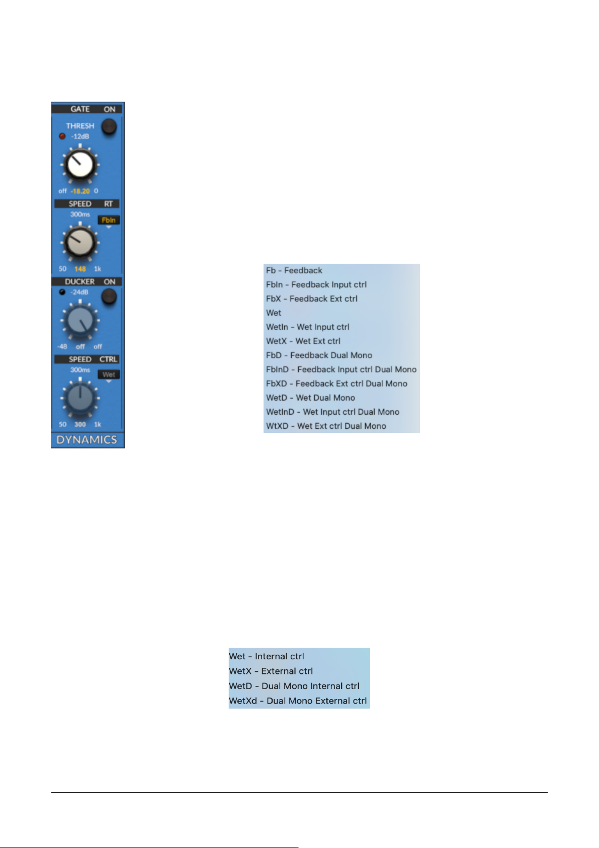
Gate
PSP 285 has a built-in gate algorithm. The gate attenuates the signal whenever it is below the
set threshold, and opens up when the signal comes back above above the threshold.
The gate can be placed at various routing points, depending on its intended application. For
instance, setting it up on the wet signal lets you control the number of taps of the echo. When
set up on feedback with control from the input, the feedback amount can be controlled by the
level of the input signal, or by the external sidechain input. One good application for this is to
feed a drum track through PSP 285 and set the threshold to only put delay on the downbeats.
Ducker
Using dense echo patterns on a track can ruin the clarity of the overall mix. To help prevent this,
PSP 285 has a built-in ducker with adjustable time constant and threshold and a wide selection
of control signal points.
In simple terms, whenever the control signal (e.g. input signal) is present, the wet signal is
attenuated down to –18 dB, and when the control signal disappears, the wet signal comes back
to its normal level. This automatically “thins out” the echoes so they don’t become too dense
and overwhelm the track or the mix. Since lower-level echoes are barely heard or unheard in a
busy mix, this provides clarity and “air” without harming the music.
PSP 285 13
PSP 285 Block Diagrams
PSP 285 main delay. Alternative module on inserts shown with dash lines.
PSP 285 Alternative control and processing modules.
PSP 285 14
PSP 285 Block Diagrams
PSP 285 main delay. Alternative module on inserts shown with dash lines.
PSP 285 Alternative control and processing modules.
PSP 285 14
USER INTERFACE: HOW TO USE PSP 285
NOTE:
The knob or other controls for any module that isn’t activated will be greyed out.
Some controls have additional functions, which are accessed via COMMAND-click (macOS) or
CTRL-click (Windows).
Main section
BYPASS – bypasses the plug-in. Note that the processing is still
performed in the background, even though the results are not heard.
M/S – switches to Mid/Side processing mode.
PSP 285 label – click to show the back panel, which plugin block
diagram, accesses this manual and lets you hide or show the tool tips that appear when you
hover your mouse on a control.
Mixer section
METERS – show the left and right channel input and output
signal levels.
INPUT – adjusts the input gain; this knob either attenuates or
boosts the signal prior to any processing.
MIX – sets the proportion between dry (unprocessed) and wet
(processed) signals. You can also think of this knob as setting
the overall effect depth. Note that PSP 285 uses a -6 dB pan
law, which might require input or output boosting to
compensate for the gain reduction applied at mixing.
OUTPUT – adjusts the output gain; this knob either attenuates
or boosts the output signal.
WET – switches to 100% Wet signal output and no Mix control,
for use on effect sends.
LIM – sets the brick wall limiter’s output level.
Lim LED – flashes to indicate when the limiter is in operation.
The LIM label and the Lim LED both act as invisible buttons to
toggle the limiter on and off.
PADLOCK – switch between Preset and preset-independent (Global) mode for all mixer
parameters:
Padlock open (shown at left) – Preset mode
Padlock closed (shown at right) – Global mode (note all knobs are now red)
Use Command-click (macOS) / Ctrl-click (Windows) to copy visible settings between modes.
PSP 285 15
Dynamics section
GATE module:
ON – toggles the gate on and off.
THRESH – noise gate threshold. Any signal below this level will be further
attenuated. Gating offers additional, more flexible control over the number and
level of echoes, closing the gap between standard and multi-tap delays.
Gate LED – indicates that the gate is closed.
SPEED – sets how quickly the gate takes effect, from 50 to 1000 ms.
RT (route) – sets operation points and control signals. The gate can be
controlled (triggered) by the input signal (Input ctrl), an external sidechain
input signal (Ext ctrl), or the signal at any of several insert points.
Any of these trigger signals can be linked or unlinked (Dual Mono).
The full list of control routings is shown here:
DUCKER module:
ON – toggles the ducker on and off.
DUCKER – ducker threshold. When input signals reach this threshold level, wet (processed)
signal will be automatically attenuated.
Ducker LED – indicates when the ducker is active.
SPEED – sets ducker opening speed (time).
CTRL -sets the ducker’s control signal. The ducker is always inserted on the wet signal, and can
be controlled by the internal audio signal or by an external signal present at the auxiliary
sidechain input, if there is one. The Ducker can operate on linked or unlinked (DUAL MONO)
channels.
The available CTRL options are shown below:
IMPORTANT NOTE: The Ext Ctrl sidechain option is only available if a sidechain input is
connected to PSP 285 from elsewhere in your host application (your DAW software). If Ext
Ctrl is selected without such a signal routing present, the routing will default to Input Ctrl.
PSP 285 16
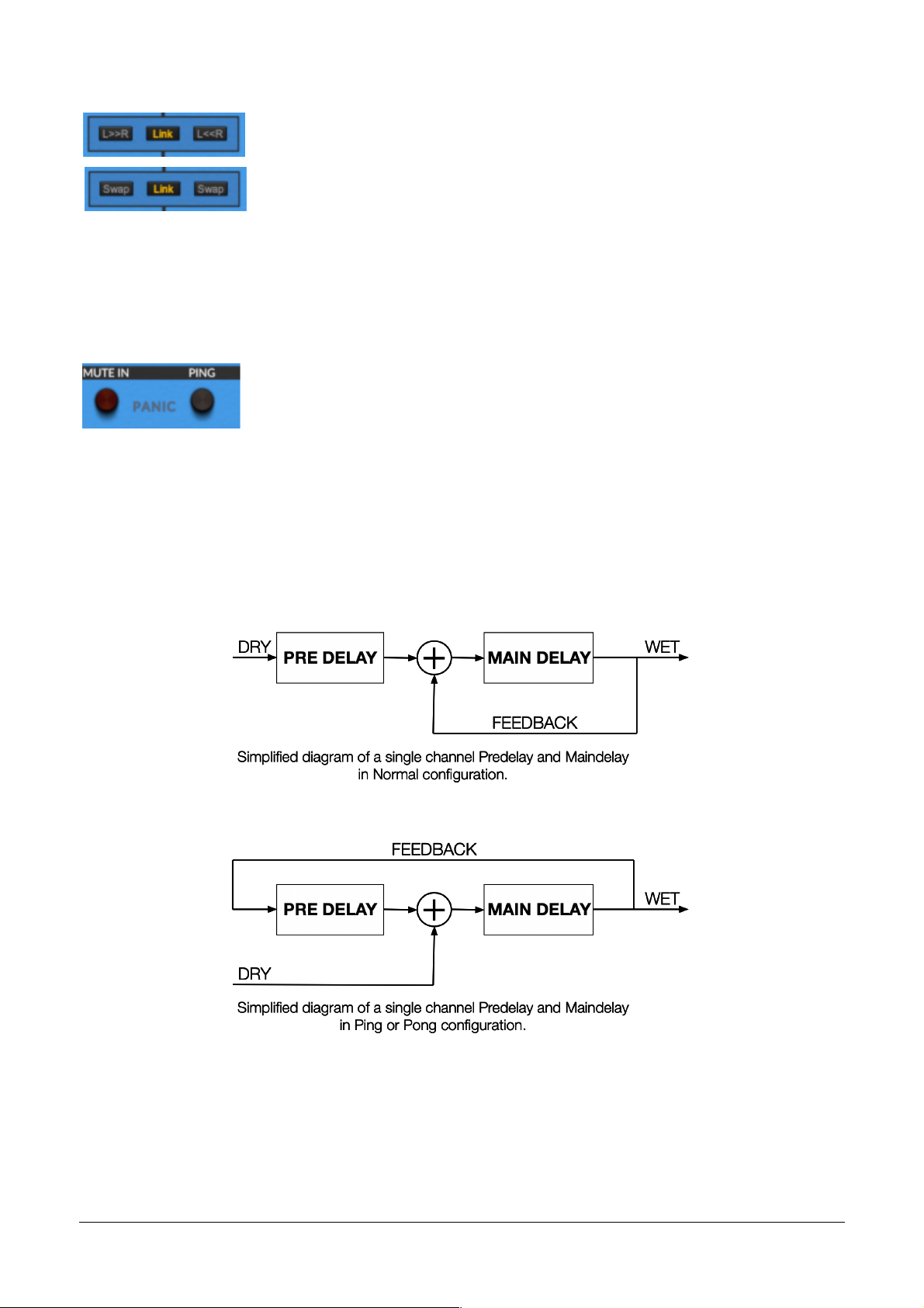
Delay section
LINK – allows both delay channels to be adjusted at the same time.
When engaged, any adjustments will affect both delay channels; note
that linked Pan controls mirror one another, so turning one knob to the
left turns the other knob to the right.
Holding COMMAND or CTRL causes whatever parameter you’re
adjusting to momentarily change from linked to unlinked, or unlinked to linked.
L>>R – copies the Left/Mid channel settings to the Right/Side channel.
R>>L – copies the Right/Side channel settings to the Left/Mid channel.
SWAP – When holding COMMAND or CTRL, the L>>R and R>>L buttons became SWAP,
which swaps all parameter settings between the two channels.
MUTE IN – mutes the delay line input. On mono tracks, clever muting and
feedback panning allows the two delay lines to be used in series.
PANIC – turns off Filter 1 and stops feedback for instant control of
unstable “runaway” sounds.
PING and PONG – sets up a ping-pong delay effect, by changing the configuration of the
Predelay and Main delays’ feedback loops as shown:
Let’s say you want to set up a ping-pong delay of 125 ms that will start on the left side. Trying to
do this with a conventional delay can be tedious and tricky to figure out: you have to set up
predelay and main delay on the two sides to produce the appropriate bounce from side to side,
without having later echoes turn mono after the initial couple of taps, etc.
To do this in PSP 285, you can simply use PING on the left channel. This mode changes the left
delay’s Pre and Main Times and reroutes the dry signal to avoid the first predelay. It also resets
the right delay’s Pre and Main Times, without the alternate routing.
NOTE: If you wanted the echo to start on the right side, you would use PONG on the right
channel, but the steps are the same.
PSP 285 17
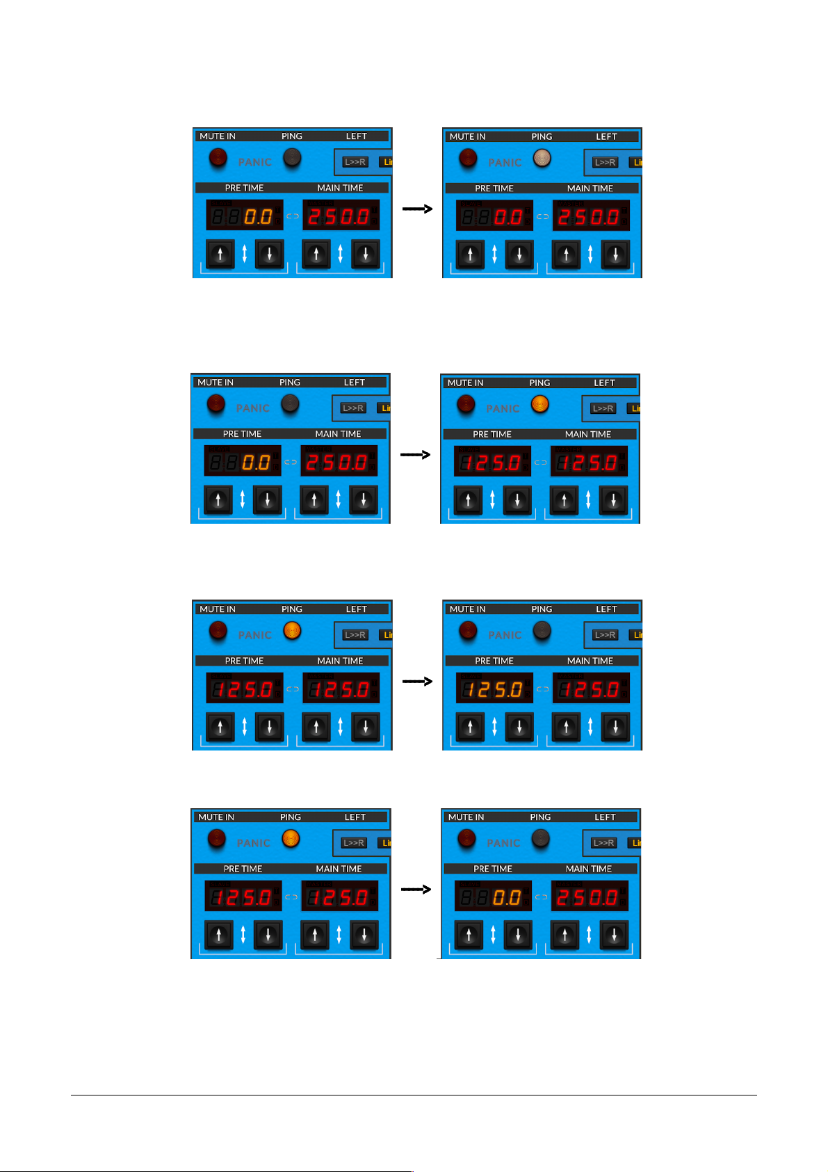
Click on the PING button to engage the Ping-Pong mode. The indicator light is white, and the
delay lengths remain unchanged. Note that the Pre Time turns red.
Now, if you COMMAND-click/CTRL-click the button (the indicator light is orange), you can
change the configuration while also recalculating the Pre and Main Times to produce the
desired effect, as shown:
If you switch back to normal mode by clicking on the PING button to turn off the indicator light,
the recalculated Pre and Main Times are preserved.
Or, you can COMMAND-click/CTRL-click the button to retrieve your original delay values.
This is a great way to create unusual stereo multi-tap rhythms: just use PING or PONG to set
up a basic effect, then individually tweak the Pre and Main Times for the Left and Right delays
to create the rhythms you want. Try experimenting with turning PING and PONG off and on in
PSP 285 18

various configurations, to hear how the various echoes change position in the stereo
panorama: sometimes on the left, sometimes on the right, sometimes in the center.
DISPLAY – When a delay time parameter is
being edited, its value is displayed here as a
time in milliseconds or as a note value, with T
to indicate triplets or D to indicate dotted notes. Click on it to
directly type in a time value in milliseconds, or to pop up a
menu with note values to choose from. Pressing the SHIFT key
gives you a wider set of note values to scroll through.
PRE TIME – Predelay time, applied to the input signal before it enters the feedback loop.
MAIN TIME – Main delay time, which is also the length of the feedback loop. With zero
feedback, a single echo will be heard after (PRE TIME + MAIN TIME).
UP/DOWN – These arrows turn delay time up or down in 1 ms increments.
Hold down SHIFT to increment by 0.1 ms for finer control. The icon with the
up and down arrows between the two buttons is an “invisible slider” that lets
you click and drag for very fast coarse time adjustments. You can also hover your mouse over
the display and use its scroll wheel.
RANGE – chooses a delay time range (only active in Time mode). You can choose between
50 ms, 500 ms, and 5000 ms (5 seconds). Smaller ranges allow for finer delay time adjustments.
MODE – delay time mode. Two modes are available:
Time – the time is expressed in milliseconds and doesn't follow tempo changes
Note – the time is expressed as a note value (rhythmic figure) related to tempo
The delay time settings in milliseconds (Time mode) and note values (Note mode) are
independent of one another.
COPY TO – copies the delay time setting from one mode to the other. Copying a note value to a
time in milliseconds will be exact; copying a time in milliseconds to a note value will not, as the
value will be quantized to the nearest note value at the current tempo.
LINK – links the Pre Time to the Main Time in a fixed proportion.
The chain link icon between the displays turns linking on/off and is illuminated
when turned on. The time displays will say SLAVE and MASTER when linked.
When you change the Main Time, the Pre Time will change proportionally. When you change
the Pre Time, the Main time stays unchanged.
PSP 285 19

EXAMPLE 1: If the Pre Time is set to 1/2 of the Main time, then changing Main Time from 250
to 200 changes the Pre Time from 125 (1/2 of 250) to 100 (1/2 of 200).
EXAMPLE 2: Changing the Pre Time doesn’t alter the Main Time; instead, it changes the
proportion between Pre and Main. Here, changing the Pre Time from 125 to 5 changes the
proportion from 1/2 (125/250) to 1/50 (5/250). Now, if you change the Main Time, the Pre
Time will adjust so it remains 1/50 of the Main Time.
FB-PAN – feedback return panning. Can be used to route part or all
of the feedback signal to the other delay channel.
FEEDBACK– the gain reduction applied to the feedback signal on
each circulation. Controls the number and level of echoes.
PAN (DELAY) – delay output panning. Each delay line (channel) can
be panned independently.
In Mid/Side mode, both controls operate as ordinary Left/Right
pans.
NOTE: In the Mid/Side mode, both pan controls work as ordinary Left-Right panpots.
GAIN – delay output gain.
Feedback INV – inverts the phase of the feedback return.
Delay INV – inverses the phase of the delay signals.
Both of the INV settings are usually only audible when delay time is short. They are useful for
chorus/flanger effects.
Delay Control section
MANUAL – directly changes the delay line’s sample rate. This knob not only
changes the delay time, but also results in an abrupt pitch shift, which will be
audible as long as the audio in the delay buffer is played back at a speed
different from the one at which it was captured.
DLY MOD – sets the delay line sample rate modulation depth.
ON (DLY MOD) – turns delay line sample rate modulation on or off.
PSP 285 20
Table of contents
Other PSP Recording Equipment manuals


