Pts PTS-G5K13M User manual

User’s Manual
PTS-G5K13M
RF Generator 5kW / 13MHz
PTS co.,Ltd.
68-1, Sangdeok-ro, Idong-myeon,
Cheoin-gu, Yongin-si, Gyeonggi-do,
#17126, Korea
Tel. 031-321-5670
Fax. 031-332-5670

PTS-G5K13M PTS Co., Ltd. 2
목
Contents
1. Safety Precautions
2. System Standard
3. Dimensions
4. RF Generator System Overview
5. Installation
6. A/D Interface
7. RS232C Communication
8. Handy Controller (Remote Operations)
9. Interlock and Alarm
10.Warranty and Maintenace

PTS-G5K13M PTS Co., Ltd. 3
1. Precautions
Safety precautions.
Be sure you read the instructions bellow before using the generator.
In case the device is damaged due to user negligence or abnormal use up on our
Security Seal, it would not be guaranteed.
Do not remove screws or open covers.
Do not modify or replace any parts of this product.
Do not block product ventilation port(s).
Make sure that all cables and connectors are properly connected as indicated on
the diagrams contained in this manual.
Ground the Equipment.
To prevent electrical shock by the AC power source, please make sure that the
equipment is securely connected to ground.
If the product generates any abnormal smells or noises during use, immediately
switch the power off and unplug all power cables including AC adapter from the
outlet.
Make sure power for all equipment is turned OFF before connectors are
connected.
Make sure that all cables and connectors are properly connected.
Do not operate this equipment in the potentially explosive environment.
Do not operate the generator in area where flammable or explosive gases stored

PTS-G5K13M PTS Co., Ltd. 4
or used.
Do not subject to vibrations or shocks. Doing so may result in product damage or
malfunction.
Use and store in a level and stable place.
Do not touch any of the electrical components.
It is allowed for the user to open the Case (chassis) of the generator.
In case the user faces a problem, our internal verification is required to open the
case.
Opening the Case without written permission from us, may cause serious
problems in the internal Parts product during operation. For such problems we
are not responsible under any circumstances.
This equipment should not be inspected by one person only.
Make sure that the person who operates the RF Generator is always around.
Do not change parts or modify this equipment.
Unauthorized Parts modification or change may cause serious problems. Please
contact us up on replacement or modification.
Pay attention to warnings and cautions.
All warnings and cautions mentioned in the Manual would advance warning of potential
hazards to prevent accidents (see following safety symbols).
Thank you for using our RF Generator. PTS and our employees would always be there to
manage customer's request. As much as possible, we will do our best to improve
customer’s service quality.
PTS-G5K13M PTS Co., Ltd. 5
Safety Symbols
This symbol indicates an imminently hazardous
situation such as electric shock and careless operation,
which, if not avoided, will result in serious injury or
worse.
It warns that there is a potential risk.
A symbol shows a care that should be taken to avoid
danger or mistakes.
It tells you potential activities to reduce serious damage
This sign is physical damage due to high voltage.
It warns the product weights more than 20kg, and tells
to Use Lifting Aids with Proper Lifting Techniques to ask
for help.

PTS-G5K13M PTS Co., Ltd. 6
This symbol is asked to refer to the Manual for reliable
equipment operation.
This symbol indicates the position where one has to
connect Ground for reliable equipment operation.

PTS-G5K13M PTS Co., Ltd. 7
2. System Standard
2-1 Basic specifications
Model
PTS-G5K13M
Output Power
0~5,000W(R=50ΩLoad)
Output Frequncy
13.56MHz
Output Impedance
50Ω±2Ω
Output Connection
“HN”Type Connector
Control Method
Output Power Control by CPU
Cooling Method
Water Cooling + Forced Air
Water : 7ℓ/min, 0.5Mpa, 10~35℃, PH7~8
Air : 1.5㎥/min
Remote Terminal
Analog Control(D-Sub 25Pin)
RS-232C Control *Option
Ambient Temperature range
5~40℃
Output Method
Continuous
Power Supply
AC 200V ±10% 3Φ50/60Hz
Consumption Power
약15kVA
Size
480 * 149 * 600
2-2 Output Specifications
Frequency Stability
±0.005% (5~40℃)
Output Devation
±2%와50W중큰것(25℃, 50ΩLoad)
Hamonic
-45dB(below)
Output Stability
±2% (25℃, 50ΩLoad)

PTS-G5K13M PTS Co., Ltd. 8
2-3 Control Specification
The RF Generator is Analog mode and Manual Mode by which RS-232C
output control is possible (on request, Device-net control would be available
as optional specification).
①Analog Mode
Via D-sub 25 pin terminal on the back of Generator, power can be
controlled through interlock confirmed by Analog Voltage.
②Manual Mode
Connect the Handy Controller provided on the front of the Power Control.
Setting Parameters can be various to make the Interlock OK.
③RS-232C Mode(Device-net option available up on selection)
Via RS-232C terminal (Device-Net Selectable) on the rear of Generator,
Power Control can be controlled.
2-4 Installation site
①Please maintain the ambient temperature to 5 ~ 40 ℃ when the generator
is in operation( Power output ON)
②Please keep in storage area of temperature -25 ~ 55 ℃ when it is not under
operation.
③Do not install in places with high humidity, dusty, where there is a direct
sunlight or places where there is any risk of water or other liquid leakage.
Getting the product wet with water or other liquid may cause damage that
cannot be repaired.
④Use and store in a level and stable place.
2-5 Installation Requirements
①Fill out the front and rear of the cooling fan blower of the product smoothly.
②Rack 적재시 전면부(>15cm), 측면부(>15cm), 후면부(>30cm)여공간과
Rack의전면부, 후면부에 배기구를 설치해 주십시요.
Generator 후면부의 열기가 축적되지 않게 해주십시요.
③Generator Rack에6㎥/min이상의 배기팬을 설치하여 주십시요.

PTS-G5K13M PTS Co., Ltd. 9
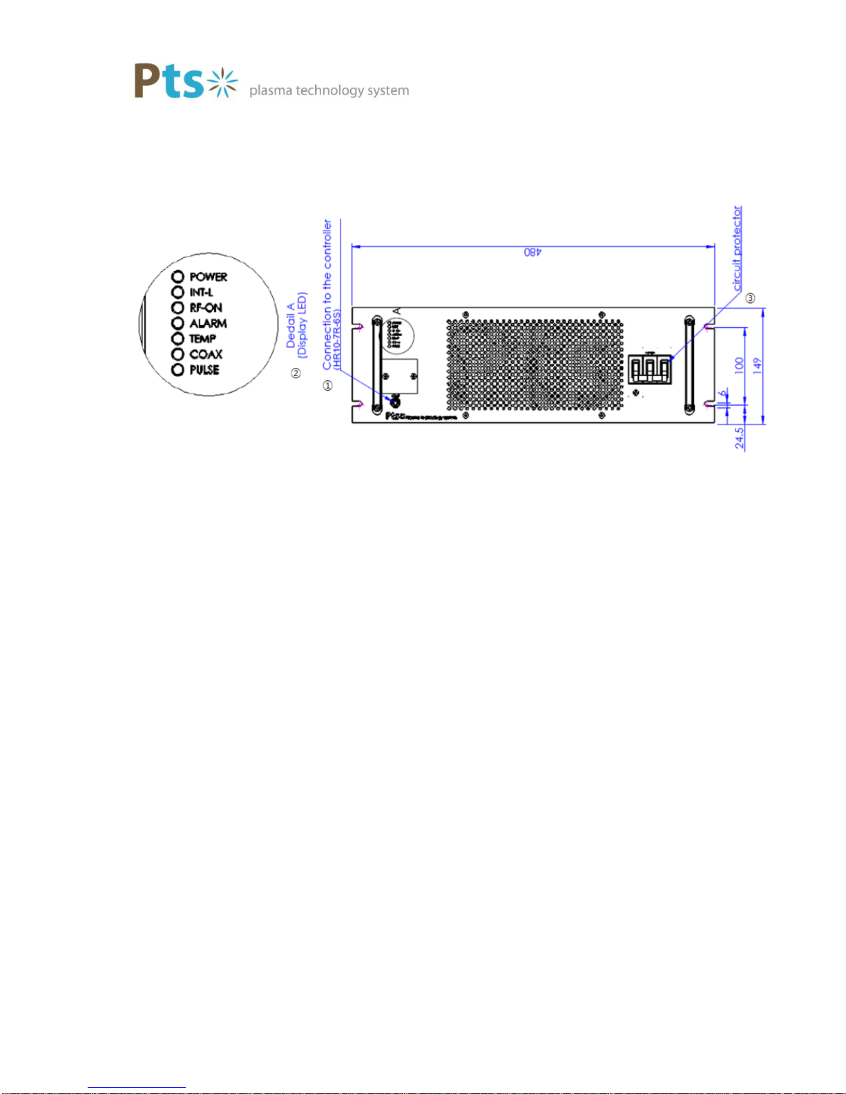
3. Dimensions
PTS-G5K13M PTS Co., Ltd. 10
4. RF Generator System Overview
4-1 Front Panel
①Handy Ctrl
Connect the Handy Controller to set the operation of the Generator.
②Status Display LED
POWER It displays the main power input status. It lights when power is turned
on.
INT-L External interlock light turns on when normal.
RF-ON LED Light turns on when RF-On is on.
ALARM Light turns on when there is a warning.
TEMP Light turns on when high temperature reading is there.
COAX Light up when COAX cover removed.
PLUSE
③Circuit protector Main Switch
PTS-G5K13M PTS Co., Ltd. 11
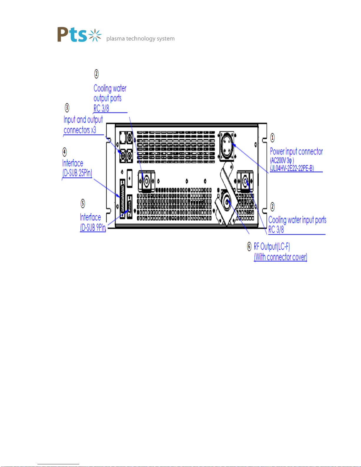
4-2 Rear
①Power Input Main power input (JL04HV-2E22-22PE-B)
②Water Cooling Water Cooling input (RC-3/8)
Water Cooling output (RC-3/8)
③Input and Output Pulse input connector
RF control pulse at the output by an external pulse signal
(BNC –R)
Pulse output connector
④Analog Interface D - SUB connector, 25P for the A / D Interface (XM2C - 2512)
⑤RS-232C (D-SUB) D-SUB, 9P connector for RS-232C communication (XM2C-
0912)
PTS-G5K13M PTS Co., Ltd. 12
⑥RF Out RF output connector ( 'HN' Type Female) & Connector cover
5. Installation guide
There is a risk of electric shock. Please be careful when installing the items below.
●Before connecting AC220V, turn of the power switch and circuit breaker.
●After the power switch and the circuit breaker is OFF, connect the coaxial cable to
the output terminal of the Generator.
●Make sure the cooling water is inflow before you switch on the RF power output.
5-1 Cable Connection
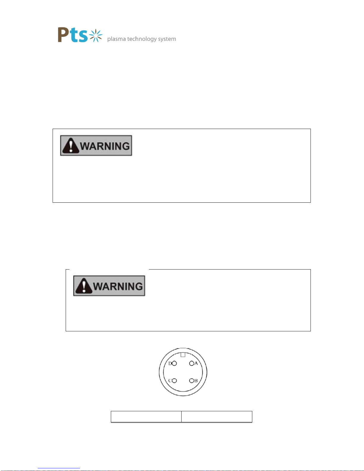
Power Connection
Always, turn Off power switch and circuit breaker of the power supply before connecting
the RF Generator.
There is a risk of electric shock, unless you connect the power cable is connected to
each phase and ground. Please check that it is properly connected.
Power Plug
Pin #
Phase

PTS-G5K13M PTS Co., Ltd. 13
A
R
B
S
C
T
D
N
RF Connection
Make sure the power is switched OFF, the Matching Unit and Generator Output
is are connected using coaxial cable.
Control Connection
Analog Interface(Analog Voltage Control)
Connect a Control Signal to the Analog Interface Terminal (D-Sub 25pin)
Confirm whether interface 3-5 connected to A/D interface(Pin assignment).
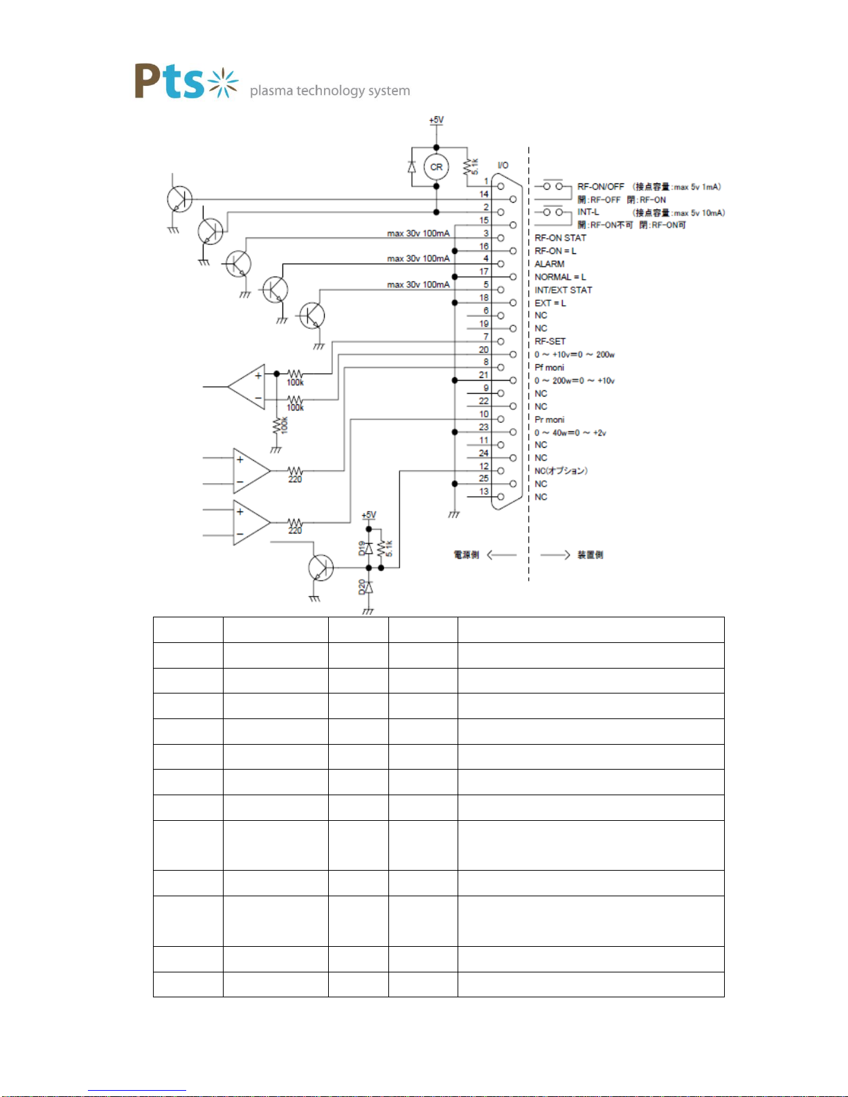
6. A/D Interface (Pin Assignment)
PTS-G5K13M PTS Co., Ltd. 14
Pin No.
Name
I/O
Type
Function
1
RF-On,Off
Input
Contact
RF on/off(Max 5V 1mA)
2
INT-L
Input
Contact
Interlock(Max 5V 1mA)
3
RF On Status
output
Analog
RF on Status(Max 30V 100mA)
4
ALARM
Output
Analog
ALARM(Max 30V 100mA)
5
INT/EXT STAT
Output
Analog
INT/EXT Status(Max 30V 100mA)
6
NC
7
RF Set
Input
Analog
RF Set Voltage(0~+10V=0~1000W)
8
Pf moni
Output
Analog
FWD Monitoring
Voltage(0~+10V=0~1000W)
9
NC
10
Pr moni
Output
Analog
REF Monitoring
Voltage(0~10V=0~1000W)
11
NC
12
NC

PTS-G5K13M PTS Co., Ltd. 15
13
NC
14
D-GND
Input
Contact
RF-On Return
15
A-GND
Input
Contact
Interlock Return
16
A-GND
Output
Analog
RF-On Status Return
17
A-GND
Output
Analog
ALARM Return
18
A-GND
Output
Analog
Int/Ext Status Return
19
NC
20
A-GND
Input
Analog
RF-Set Return
21
A-GND
Output
Analog
FWD Monitor Return
22
NC
23
A-GND
Output
Analog
REF Monitor Return
24
NC
25
NC
※Please use D-GND and remove A-GND.
Analog Interface Connector Pin Functions
①RF On/Off (RF power On/Off Signal)
Pin 1,14 Open while RF off, and Close while RF On
②INT-L (Interlock Signal)
Pin 2,15 Open if no RF power, Close if there is RF power
③RF On Status (RF Power Output Signal)
Pin 3,16 Open when the generator is in Idle, Close when RF Power is
applied/RF power on state /
④ALARM (Generator internal Alarm Signal)
Pin 4,17 Open when normal. Close when internal problem occurs
⑤INT/EXT Status (INT / EXT Signal state)
⑥RF Set (RF Power Set voltage)

PTS-G5K13M PTS Co., Ltd. 16
Pin 7 (Set RF ) ) to a 0 ~ 10V, RF Output Power Set 0 ~ 3,000W to 20 ( A - GND ).
⑦Pf Moni(FWD Power Monitor)
7. RS232C Communication
7-1 Communication Specification
Baudrate
57,600bps
Data width
8bits
Parity
Even
Flow control
none

PTS-G5K13M PTS Co., Ltd. 17
7-2 Communication Protocol
<————————— Length —————————>
SM
LEN
ID
CMD
DATA
CRC
EM
<———————————— CRC ————————————>
Name
Size
Function
SM
1
Start Marker (0x05)
LEN
1
Length
ID
1
ID
CMD
1
Command
DATAn
n
DATA field
CRC
1
CRC (XOR calc.)
EM
1
End Marker (0x0A)

PTS-G5K13M PTS Co., Ltd. 18
No FUNCTION
DIR
CTRL-RFU
START
CODE
LEN ID
CMD D0 D1 D2 D3 D4 D5 CRC
END
CODE
1 set rf-gen. output mode
→05 04 80 00 XX 0A
2 get rf-gen. status
→05 02 80 40 XX 0A
3 respond rf-gen. status
←05 04 80 C0 XX 0A
4 set pf-pwr.
→05 04 80 01 XX 0A
5 get pf-pwr.
→05 02 80 41 XX 0A
6 respond pf-pwr.
←05 04 80 C1 XX 0A
7 get current pf-pwr.
→05 02 80 42 XX 0A
8 respond current pf-pwr.
←05 04 80 C2 XX 0A
9 get current pr-pwr.
→05 02 80 43 XX 0A
10 respond current pr-pwr.
←05 04 80 C3 XX 0A
11 set slow-up time
→05 04 80 04 XX 0A
12 get slow-up time
→05 02 80 44 XX 0A
13 respond slow-up time
←05 04 80 C4 XX 0A
14 get arc-cut count
→05 02 80 45 XX 0A
15 respond arc-cut count
←05 04 80 C5 XX 0A
16 getpwr
→05 02 80 46 XX 0A
17 respond pwr
←05 08 80 C6 XX 0A
18 reset alarm
→05 02 80 3E XX 0A
19 get status
→05 02 80 7F XX 0A
20 respond status
←05 06 80 FF XX 0A
21 normal response
←05 03 80 CMD*1 01 XX 0A
22 abnormal response
←05 03 80 CMD*1 ER*2 XX 0A
*1: if request command is "set" then 2'b10XXXXXX(X=base command) fixed
if request command is "get" then 2'b11XXXXXX(X=base command) variable
*2: ER(Error Code) null
0xF0:Communicaton Error
0xF1:CRC Error
0xF2:Data Error
0xF3:E2PROM Error
PF
CPF
CPR
RFS
ACC
TIME
TIME
ACC
PF
PF
CPF
CPR
RFS
RFS

PTS-G5K13M PTS Co., Ltd. 19
7-3 Communication Command Information
1.set rf-gen. output mode
3.respond rf-gen. status
15 1 0 15 14 13 12 11 10 9 8 7 6 5 2 1 0
rm hd rsv ap fl pt cx il ta sb al rm os
.
4.set pf-pwr 6.respond pf-pwr
15 14 13 015 14 13 0
8.respond current pf-pwr
15 14 13 0
10.respond current pr-pwr
15 14 13 0
11.set slow-up time 13.respond slow-up time
15 13 12 015 13 12 0
0:normal, 1:abnormal
[14]
reserved
[12]
flow
0:normal, 1:abnormal
slow-up time unit is "ms".
slow-up time
300~5,000(0x012C~0x1388)
[15:13]
null
[NOTE]
not assignment. read data is '0'.
[12:0]
not assignment. write data is '0'.
[NOTE]
slow-up time unit is "ms".
[cmd]
0xC4
[id]
0x80
sutw
[id]
0x80
[12:0]
slow-up time
300~5,000(0x012C~0x1388)
[15:13]
null
[NOTE]
current pr-power unit is "W".
[cmd]
0x04
0~10,000(0x0000~0x2710)
[15:14]
null
not assignment. read data is '0'.
[id]
null
cprr
0x80
[13:0]
pr-power(monitor)
[NOTE]
current pf-power unit is "W".
[cmd]
0xC3
0~10,000(0x0000~0x2710)
[15:14]
null
not assignment. read data is '0'.
0xC2
[id]
null
cpfr
0x80
[13:0]
pf-power(monitor)
rf output mode
0:CW, 1:PULSE
[5:2]
reserved
[cmd]
[13]
AMP
[6]
alarm
0:normal, 1:abnormal
[7]
stand-by
0:OK, 1:NG
[8]
temp. abnormal
[10]
coax
0:normal, 1:abnormal
0:normal, 1:abnormal
[9]
interlock
0:normal, 1:abnormal
[cmd]
0x01
[cmd]
0xC1
[id]
0x80
[13:0]
pf-power
0~10,000(0x0000~0x2710)
pfw
null
[15:14]
null
not assignment. write data is '0'.
[NOTE]
pf-power unit is "W".
[id]
null
pfr
0x80
[13:0]
pf-power
0~10,000(0x0000~0x2710)
[15:14]
null
not assignment. read data is '0'.
[NOTE]
pf-power unit is "W".
write data is '0'.
0:disable, 1:enable
[NOTE]
0:CW, 1:PULSE
0:disable, 1:enable
[15:1]
reserved
[1]
0x80
0x80
[0]
rf output mode
[0]
[id]
reserved
[cmd]
[cmd]
0x00
0xC0
[id]
reserved
power output state
[NOTE]
[15]
HD CON
null
null
sutr
[11]
pr-trip
0:normal, 1:abnormal

PTS-G5K13M PTS Co., Ltd. 20
15.respond arc-cut count
15 7 6 0
17.respond pwr
47 46 45 32 31 30 29 16 15 14 13 0
20.respond status
15 14 13 12 11 10 9 8 7 6 5 2 1 0
hd rsv ap fl pt cx il ta sb al rm os
31 23 22 16
.
0:normal, 1:abnormal
pf-power(monitor)
0~10,000(0x0000~0x2710)
[12]
flow
[47:46]
null
[15:14]
null
not assignment. read data is '0'.
[29:16]
[31:30]
pf-power
cpfr
not assignment. read data is '0'.
[NOTE]
[13:0]
0~10,000(0x0000~0x2710)
0x80
null
null
null
pfr
cprr
0xC6
[6:0]
[id]
0x80
[15:7]
0xC5
[id]
[cmd]
null
0~100(0x0000~0x0064)
arc-cut count
null
acr
[cmd]
[45:32]
pr-power(monitor)
0~10,000(0x0000~0x2710)
[NOTE]
[cmd]
0xFF
[id]
not assignment. read data is '0'.
0x80
[0]
power output state
0:disable, 1:enable
[5:2]
reserved
null
acr
[1]
[6]
alarm
0:normal, 1:abnormal
[7]
stand-by
0:OK, 1:NG
[8]
temp. abnormal
0:normal, 1:abnormal
[11]
pr-trip
0:normal, 1:abnormal
[9]
interlock
0:normal, 1:abnormal
[31:23]
null
not assignment. read data is '0'.
[NOTE]
[22:16]
arc-cut count
0~100(0x0000~0x0064)
[15]
HD CON
0:disable, 1:enable
0:normal, 1:abnormal
[10]
coax
reserved
[13]
AMP
0:normal, 1:abnormal
[14]
reserved
rf output mode
0:CW, 1:PULSE
null
not assignment. read data is '0'.
Table of contents
Other Pts Portable Generator manuals


