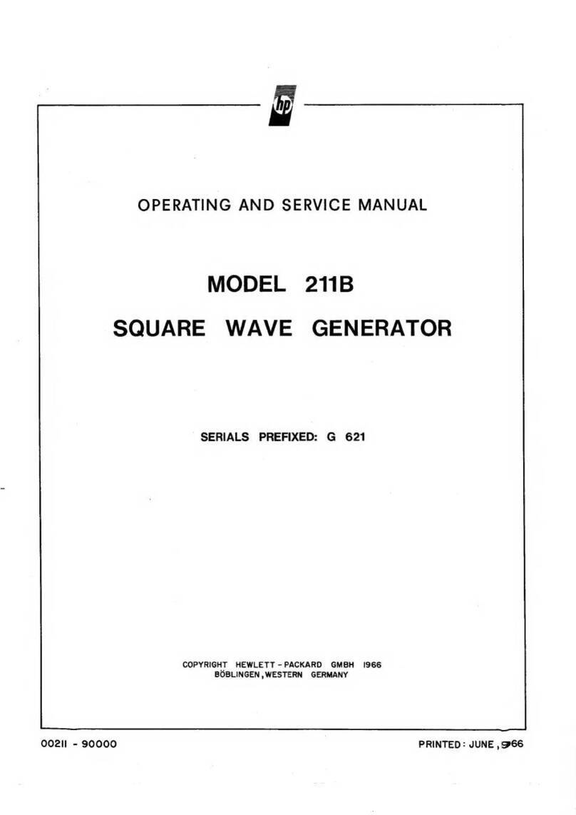
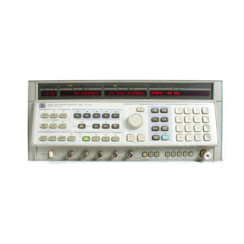
HP 214B Service manual

!
\
~
PERATING
AND
SERVICE
MANUAL
2148
PULSE
GENERATOR
--- -
---..
-
-"
--
--
-
--
--- -
~
2148
PULSE GENERATOR
~
HEW~fTT
PACK.RO
MODE
RA
TE
IH,)
PERIOD(.)
PULSE
POSlTlONII'
WIDTH.t)
ANiPlITUOE
1\1>
~IlT
' O
L'
'"
_
'"
• 10" •
'.
,,, -
00
~
• • •
/;1011'"
nile
GATE
~
H~
,~
-
I~
-10
..
-
,,,,
_
1m
-
10m
- 1
'On'
I.. - I.. -101'
I,.,
- ,
...
-
10",
25
n I.. '
'"
-10.. ' , ... -
,'"
•
10",
l • 1
l'
'0
30
-
'00
.... ....
..
......
~
......
...
.
_'''''''(00".
__
-'---
. _ _ _ •
T~
u_
taT
'''i'UIIU
-
J<tU"IEAOfPUlSES-
,
, , .
f2~
-:tV
-
.,..,
LIHE • SLOPE EXT I
NPUT
lAta
OUTPUT
r
h
~
HEWLETT
~
~
PACKARD

DIGITALY REMASTERED
OUT OF PRINT
HEWLETT PACKARD MANUAL SCANS
By
Artek Media
18265 200th St.
Welch, MN 55089
www.artekmedia.com
“High resolution scans of obsolete technical manuals”
ALL HEWLETT PACKARD MANAULS ARE REPRODUCED BY PERMISSION
AND UNDER LICENSE AGREEMENT WITH AGILENT TECHNOLOGIES, INC.
REMOVAL OF THIS DISCLAIMER IS INVIOLATION OF AGILENT
TECHNOLOGIES AND ARTEK MEDIA’S COPYRIGHTS. DUPLICATION OR
MODIFCATION OF THIS DIGITAL DOCUMENT WITHOUT PRIOR CONSENT
IS NOT PERMITTED
If your looking for a quality scanned technical manual in PDF format please visit
our WEB site at www.artekmedia.com or drop us an email at
manuals we have available.
If you don’t see the manual you need on the list drop us a line anyway we may
still be able to point you to other sources. If you have an existing manual you
would like scanned please write for details. This can often be done very
reasonably in consideration for adding your manual to our library.
Typically the scans in our manuals are done as follows;
1) Typed text pages are typically scanned in black and white at 300 dpi.
2) Photo pages are typically scanned in gray scale mode at 600 dpi
3) Schematic diagram pages are typically scanned in black and white at 600
dpi unless the original manual had colored high lighting (as is the case for
some 70’s vintage Tektronix manuals).
4) Most manuals are text searchable
5) All manuals are fully bookmarked
All data is guaranteed for life (yours or mine … which ever is shorter). If for ANY
REASON your file becomes corrupted, deleted or lost, Artek Media will replace
the file for the price of shipping, or free via FTP download.
Thanks
Dave & Lynn Henderson
Artek Media
.--------Fli;.
HEWLETT
_______
.---,
~~
PACKARD
OPERATING
AND
SERVICE
MANUAL
2148
PULSE GENERATOR
(Including Options
001
and 907
to
910)
SERIAL Nur.1BERS
This manual applies
directly
to
instruments
with
serial
number
1846 G
00596
and higher.
Any
changes made in
instruments having serial numbers higher than
the
above
number
will
be
found
in a "Manual Changes" supplement
supplied
with
this
manual.
Be
sure
to
examine
this
supple-
ment
for
any changes
which
apply
to
your
instrument
and
record these changes in the manual.
Any
changes made in
instruments havi
ng
serial numbers lower than the above
number
can
be
found
in
the
Backdating Section 7.
© HEWLETT·PACKARD GmbH 1980
0·7030
BOBLINGEN, HERRENBERGER STR. 110
FEDERAL
REPUBLIC OF
GERMANY
MANUAL
PART NO.
00214-90012
Microfiche Part No.
00214-95012
Printed: March 1980
Scans by Artekmedia => 2009

CERTI
FICATION
Hewlett
·
Packard
Company
certifies
that
this
product
met
its
published
specifications
at
the
ti
me
of
shipment
from
the
factory.
Hewlett-Packard
further
certifies
that
its
calibration
measurements
are traceable to the
United
States
National
Bureau
of
Standards,
to
the
extent
aI/owed
by
the
Bureau
's
calibration
facility
,
and
to the
calibration
facilities
of
other
Interna·
ti
ona
l
Standards
Organi
z
at
i
on
members
.
WARRANTY
Th
is
Hewl
e
tt
·Packard
product
is
warranted
against defects
in
material
and
workmanship
for
a
peri
od
of
one year
from
date
of
shipment.
During
the
warranty
period,
Hewlett
·Packard
Company
will,
at its
option
,
either
repair
or
replace
products
which
prove
to
be defective.
HP
warrants
that
its software and
firmware
designated
by
HP
for
use
with
an
instrument
will
execute its programming instructions when
properly
installed
on
that
instrument
.
HP
does
not
warrant
that
the
operation
of
the
instrument,
or software,
or
firmware
will
be
uni
nterrupted
or error free,
For
pr
o
ducts
returned
to
HP
for
warranty
service,
Buyer
shall prepay shipping charges
to
HP
and HP shall pay
shipping
charges
to
return
the
product
to
Buyer.
However,
Buyer
shall
pay
all
sh
i
pping
charges, duties, and taxes
for
products
returned
to
HP
from
another
country
.
LIMITATION
OF
WARRANTY
The
foregoing
warranty
shall
not
apply
to
defects resulting
from
improper
or
inadequate
maintenance
by
Buyer,
Buyer·supplied
software or
interfacing,
unauthorized
modification
or
mi
suse
,
operation
outside
of
the
environmenta
l
specifications
for
the
product,
or
improper
site
preparation
or
maintenance.
NO
OTHER
WARRANTY
IS
EXPRESSED
OR
IMPLIED,
HP
SPECIFICALLY
DISCLAIMS
THE
IMPLIED
WARRANTIES
OF
MERCHANTABILITY
AND
FITNESS
FOR A
PARTI
·
CULAR
PURPOSE,
EXCLUSIVE
REMEDIES
THE
REMEDIES
PROVIDED
HEREIN
ARE
BUYER'S
SOLE
AND
EXCLUSIVE
REMEDIES.
HP
SHALL
NOT
BE
LIABLE
FOR
ANY
DIRECT,
INDIRECT,
SPECIAL,
INCIDENTAL,
OR
CONSEQUENTIAL
DAMAGES
,
WHETHER
BASED
ON
CONTRACT,
TORT,
OR
ANY
OTHER
LEGAL
THEORY.
ASSISTANCE
Product
maintenance
agreements
and
other
customer
assistance agreements are
available
for
Hewlett·Packard
products.
For
any
assistance,
contact
your
nearest
Hewlett·Packard
Sales
and
Service
Office
.
Addresses are
provided
at
the
back
of
this
manual,
I
J
f
;
Scans by ArtekMedia => 2009

Model 214B
List
of
Contents
CONTENTS
Page
Section 1
GENERAL
INFORMATION
1- 1
Introduct
ion
1-1
1- 4 Specifications . . . . . . . . . . . . . . . . . . . . . . . . . . . . . . .
..
1-1
1- 6 Safety Considerations . . . . . . . . . . . . . . . . . . . . . . . . .
..
1- 1
1- 9
1-
11
1- 16
Instruments Covered by M
an
ual
De
scr
iption
Options
Section 2
INSTALLATION
2-
1
2
-3
2- 5
2- 6
2-10
2- 13
2-
15
2-17
2- 18
2-20
Introduction
I
niti
al Inspection
Preparation
for
Use
Power Requ irements
..
.
..
.
..
.
..
. .
...
.
.......
.
Power Cable .
....
..
.
...
. .
..
.
..
.........
..
. .
Operating
Environment
Front
Handle/Rack
Mo
unting
Claims and Repackaging
..
...
.
..
. .
..
....
. .
....
...
. .
Claims
for
Damage
..
...
....
........
....
. .
..
. .
Storage and
Shipment
... ...
..
.......
.
...
..
.
....
..
.
Section 3
OPERATION
3-1
3-3
3-6
3- 9
3-11
3-
15
3-
19
3-23
3-
26
3-
29
3-
31
Introduction
..
....
....
...............
. . . . . .
..
. .
Special Ope
ra
ting
Consi
de
ratio
ns
. .
..
.......
.
......
. . .
Operating Mode
....
. .
......
...
...
. .
..
..
..
..
. . .
Norm
Mode
...
......
..
.
...
.
.......
...
..
...
...
.
Ext.
Trigger Mode
............
........
..
....
..
. .
Gate Mode .
..
..
......
..
...
.........
.
..
.
....
.
Pulse Position
..
...
.
.....
.........
. .
......
..
. . .
Duty
Cycle
...
.
..
.
....
.
.. ..
.
.......
..
.
....
..
. .
Constant
Duty
Cycle Mode .
..
....
.....
.... ....
. . .
Amplitude
Polarity
Section 4
PERFORMANCE
TESTS
4-1
4- 3
4- 5
4- 7
4- 10
4-
11
4-
12
4-
13
4- 14
4- 15
4-
16
4-
17
4-
18
Introduction
...
. .
...........
...
.
....
...
.
....
.
Equipment
Required
....
..
....
.........
..
.
..
...
. .
Test Record
Performance Tests
Repetition
Rate; Vernier Accuracy
Pulse Position: Delay; Advance; Vernier Accuracy
Pul
se
Width
; Vernier Accuracy;
Ma
x.
Duty
Cycle
Constant
Duty
Cycl
e;
Vernier Accuracy
.......
.
.....
.
..
.
Pulse
Amplitude;
Verni
er
Ac
cu
rac
y;
Source Impedance
Transition
Times;
Pre
s
hoot
, Overshoot, Ringing; Pulse
Polarity
. .
Tr
igger
Output
;
Double
Pulse
.......
.
..
. .
..
... ...
. . .
External Mode
s;
Trigger; Gate; Burst
Variable Trigger Level; Se
nsitivity
1-1
1- 1
1-1
2-1
2- 1
2- 1
2-1
2- 1
2-2
2-2
2- 2
2-2
2- 2
3-1
3-1
3-1
3- 1
3-1
3- 2
3-2
3- 2
3- 3
3-3
3- 3
4- 1
4- 1
4-1
4- 1
4-2
4-4
4- 7
4-10
4- 13
4-15
4-
17
4- 19
4-
21
Contents
Scans by Artekmedia => 2009

Contents
Section 5 ADJUSTMENTS
5-1
5-3
5-9
5-11
5-12
5-13
5-14
5- 15
5-16
5-17
Introduction
Safety Considerations
Equipment Required
Power Supply
..
.
......
.. ..
.
....
.
..
...
..
....
..
. .
Period-Rate Adjust .
.......
...
....
...
..
...
...
. . . .
Position Adjust
.......
.....
.
..
...
.......
......
.
Constant
Duty
Cycle and Width
..
.
...
.......
...
....
. .
Pulse Amplitude
..
.
....
..
......................
.
Minimum Width; Overshoot; Undershoot; Risetime; Int. Load
..
Trigger Level Sensitivity
...
..
.....
.......
...
.....
.
Section 6 REPLACEABLE PARTS
6-1
I
ntroduct
ion
5-1
5-1
5-1
5-2
5-3
5-5
5-7
5-9
5-11
5-13
6-1
6- 3 Abbreviations
..
...
..
...
..
..
..
..
..
.....
.
.. ..
. . "
6-1
6-5
Replaceable Parts . . . . . . . . . . . . . . . . . . . . . . . . . . . . . .
6-1
6-8
Ordering Information .
..
..
.
....
.
.....
..
.....
. . . . .
6-1
6-11
Direct
Mail
Order System . .
...
.
...
.....
..
...
.
..
....
6-1
Section 7 BACKDATING
7- 1
Introduction.
. . . . . . . . . . . . . . . . . . . . . . . . . . . . . . . . .
7-1
7
-3
Change Sequence . . . . . . . . . . . . . . . . . . . . . . . . . . . . . .
7-1
Section 8 SERVICE
8-1
8-4
8-6
8-15
Appendix A
A1-1
A2-1
A3-1
Introduction
...
.
...
.
..
...
.
...........
..
.
...
. . .
Safety Considerations
....
.
..
.
.......
..
.......
..
. .
After Service Safety Check
..
.
..
.........
....
. .
..
. .
Service Blocks (Theory) / Troubleshooting
........
..
...
.
Option
001,
Burst Capability
Introduction
Operating Instructions
Burst Performance Test
Ust
of Illustrations
ILLUSTRATIONS
Figure
1-1
1-2
1- 3
2-1
2- 2
2- 3
3- 1
3- 2
3- 3
Title
214B and Supplied Accessories
Available Rack Mounting Accessories .
..
. . .
....
..
...
..
.
Serial Number Plate . .
.......
...
..
...
..
...
..
. . .
..
.
Switch Settings for
the
various Nominal Powerline Voltages .
..
.
Power Cbles Available: Plug Identification
.....
.
.....
. . .
Removing Plastic Trim
.....
..........
. . .
..
....
_
..
.
Controls and Connectors
...
..
.....
...............
.
214B
Outputs
in
Gate Mode
..
........
.
..
...
.......
.
Timing Parameters
in
Double Pulse Mode .
..............
.
8-1
8-1
8-1
8-1
Al-1
Al-1
A1-1
Al-2
Page
1-0
1-0
1-1
2-1
2-2
2-2
3-0
3-2
3-2
Model 214B
Scans by ArtekMedia => 2009

Model 214B
4-1
4- 2
4-3
4-4
4-5
4- 6
4- 7
4-8
4- 9
4-10
4-
11
4-12
4- 13
4-14
4-15
5-1
5-2
5-3
5- 4
5- 5
6-1
A3-1
Test
Setup
-Rep. Rate
Test
Setup
-Pulse Position . .
....
..
.
...
..
... ...
. .
Test
Setup
-Delay
......
. .
..
.. ..
. . . .
..
.....
.
..
. .
Test
Setup
-Width
..
.
....
.
..
..
.
...
.
..
...
. . .
Test
Setup
-Width
....
. . .
..
. .
.......
..
..
...
.. ..
.
Test
Setup
-Constant
Duty
Cycle . . . .
Test
Setup
-
Constant
Duty
Cycle . . . . .
..
..
.
....
......
Test
Setup
-
Amplitude
Test
Setup
-Transition Times
Test
Setup
-Trigger
Output
Test
Setup
-Double Pulse
Test
Setup
-External Modes
Test
Setup
-Variable Trigger Level
Waveform for +ve slope trigger
Waveform for
-ve
slope trigger .
...
. .
..
..
.
..
. . . . . .
Setup
for Period Adjust
...
.
..
.
..
.....
. .
....
. . . . . .
Setup
for Delay Adjust
.....
.
..
....
..
. .
.....
...
. .
Setup
for
Duty
Cycle Adjust .
...
. .
.....
.. ..
. .
..
.....
Setup
for Amplitude Adjust
Setup
for Width Adjust
Parts Identification for Main Assembly
Test
Setup
-Burst
List
of
Tables
TABLES
Table
1-1
1- 2
6-1
6-2
6- 3
8-1
8- 2
8-3
Title
Recommended
Test
Equipment
Specifications
...
.........
..
...
. .
...
.......
..
. . .
Abbreviations for Replaceable Parts
.......
.
....
.
..
. . .
Manufacturers Code List
Replaceable Parts
Index
to
Assemblies . . . .
.. ..
.....
....
. . .
Index
to
Service Blocks .
..
.
....
.
......
.
..
. .
..
...
..
.
Schematic Diagram Notes
.. ..
. . . . . .
..
.
...
. .
.....
. . .
SCHEMATICS
Schematic
1
2
3
4
5
6
A1-1
A1-2
A1-3
Title
214B Block Diagram
Power Supply A4
PIO Timing Board A2
PIO Timing Board A2
Output
Board A1 . . . . . . . . . . .
..
.
...
.
..
. .
..
.
..
.
PIO Timing Board A2; Load Board A3 . . . . .
..
.
..
.
PIO Timing Board A2 (Option) . . . . . .
..
.
.....
. . . . .
..
.
PIO Timing Board A2 (Option)
....
.
...
..
...
...
. . . .
PIO Timing Board A2 (Option)
.........
. . . . . .
......
.
4- 2
4- 4
4- 5
4- 7
4- 8
4- 10
4-
11
4- 13
4- 15
4-17
4- 18
4- 19
4-
21
4-22
4- 22
5-3
5- 5
5-7
5- 9
5-
11
6- 3
A3-1
Page
1- 2
1- 3
6- 2
6- 4
6- 7
8- 1
8-2
8- 3
Page
8-7
8-13
8-25
8- 27
8-
31
8- 33
A1-3
A1
- 5
.
J\
1-7
Contents
Scans by Artekmedia => 2009

General
Information
1-0
Front
handle
Order
Option
907
(H
.P. Part No.
5061-0089)
Figure
1-1
. 214B and supplied Accessories
(Option
001 f itted)
Rack flange
with
front
handle
Order Option 909
(H
.P. Part No.
5061 -0083)
Figure
1-2.
Available Rack Mounting Accessories
Model 214B
Rack flange
Order
Option
908
(H
.
P.
Part No.
5061-0077)
Scans by ArtekMedia => 2009

Model
2148
General
Information
SECTION I
GENERAL INFORMATION
1-1
INTRODUCTION
1
-2
Thi
s
Operating
and
Service
Manual
contains
informa-
tion
required
to
install,
operate,
test,
adjust
and
servi
ce
the
Hew
lett
-Pa
ckard
Model 214B_
Figure
1- 1
shows
the
main-
frame
and
accessories
supp
l
ied_
This
section
covers
in
-
strument
identification,
description,
accessories,
specifica-
tions,
and
other
basic
information
.
1
-3
A
microfiche
version
of
this
manual
is
available
on
4 x 6
inch
microfilm
transparencies
(order
number
on
title
page). E
ach
microfilm
contains
up
to
60
photo
-duplica
tes
of
the
manual
pages.
Th
e
microfiche
package
also
includes
the
l
ate
st
Manual
Changes
supplement
as well as all
pert
i
nent
Service
Notes
.
1-4
SPECIFICATIONS
1- 5 In
strument
specifications
are
listed
in
Table
1--2.
Th
ese
specifications
are
the
performance
standards
or
limits
aga i
nst
which
the
instrument
is
tested
.
1-6
SAFETY
CONSIDERATIONS
1- 7
The
Model
2148
is
a
Safety
Class 1
in
strument
(it
has
an
exposed
metal
chassis
that
is
directly
connected
to
earth
via
the
power
supp
ly
cab
le) .
1-8
This
operating
and
service
manual
contains
informa-
tion,
cautions,
and
warnings
which
must
be
followed
by
the
user
to
en
s
ure
safe
operation
and
to
ma
i
ntain
the
i
nstrument
in
a
safe
condition.
1-9
INSTRUMENTS COVERED BY
MANUAL
1-
10
Attached
to
the
rear
of
this
instru
ment
is a serial
number
plate
(F
ig
ure
1-3)
.
The
first
four
digits
of
the
serial
number
only
change
when
there
is
a signi
fi
cant
change
to
the
instrument.
The
last five digits
are
assigned
to
instrument
s
sequentially_
Th
e
contents
of
this
manual
apply
di
rectly
to
the
instru
ment
serial
number
qu
oted
on
the
title
page
.
For
instru-
ments
with
lo
wer
serial
numbers,
refer
to
the
backdating
infor-
mation
in
Section
7
of
this
manual.
For
instruments
with
higher
ser
ial
numbers,
refer
to
the
Manual
Change
sheets
at
the
end
of
this
manual.
In
addition
to
change
information,
th
e
Manual
Change
sheets
may
contain
information
for
co
rre
cting
errors
in
the
manual.
To
keep
this
manual
as
up-to-date
and
accurate
as possible,
Hewlett
-
Packard
recommends
that
you
periodically
request
the
latest Manual
Change
supplement.
The
supplement
for
this
manual
is
identified
with
thi
s
manual's
print
date
and
part
number
,
both
of
which
appear
on
this
manual's
title
page.
Complimentary
copies
of
the
supplement
are
available
from
Hewlett-Packard.
HEWLETT-
PACKARD
GmbH
[1536G
00062
I
B08l1NGEN
Figure
1-3.
Serial
Number
Plate
1-11
DESCRIPTION
1-12
The
Model
2148
is
a high
power
pulse
generator
delivering
200
watts
pulse
power
at
up
to
4 MHz
repetition
rate
and
15ns
or
less
transition
times
.
With
reduced
power,
the
repetition
rate
can
be
increased
to
10
MHz.
1-13
V
ariable
pulse
parameters
of
the
214B
include
repeti-
tion
rate,
width,
delay
/
advance;
and
duty
cycle
. In
addition,
the
214B
constant
Duty
Cycle
Mode
ensures
that
duty
cycle
remains
constant
with
a
frequency
range,
thus
main-
taining
a
constant
pulse
energy
at
the
output.
1-14
User
orientated
featu
res
of
the
2148
include
push-
button
selection
for
parameter
ranges,
calibrated
verniers
for
continuous
setting
within
these
ranges,
and
LED indica-
tions
of
timing
error
and
output
amplifier
overload.
1-15
For
a
complete
description
of
controls
and
modes
of
operation,
refer
to
Section
III.
1-16
OPTIONS
1-
17
214B-Option
001
:
This
allows
a
preselected
number
of
pulses
to
be
generated
on
receipt
of
a trigger signal.
(Not
retrofittable)
.
1-
18
2148-0ptions
907,
908
and
909:
Provides
means
of
rack
mounting
the
2148
_
Further
details
are
given
in
Figure
1- 2.
1-1
Scans by Artekmedia => 2009

General
Information
Model 214B
Table
1-1
. Recommended Test
Equipment
,-._-
--
.,--
.
_-
--_
.-
-
-_
.
_._-
.,-
---_
.
_-_
.
_._---
,
----_
..
----_
. -
--,--
_._-
-
-,
QTY
INSTRUMENT
TYPE
1
Digit
al
Multimeter
----
-
._-_
..
--
_ .
1 Sampling Oscilloscope
RECOMMENDED
MODEL
REQUI
.
RED
CHARACTER
ISTICS
REQUIRED
FOR
3465A!B
-.-
--
--.
---
-----
- .
-----
.-r--
~-
--
i
10-1000VDC,
AC;
OHM
A T
f
Flo,,;n.
In
p
",
___
.
1 GHz
Bandwidth
180C Mainframe
1810A
Sampling Plug In A ' T
1----
-+--
---------
-
..
---
.
---
.-
.
--
-
--
-
-1---
.
.....
-
...
-
----
-.
-----.
-
-t--I---+-
..•
-
1 Oscilloscope
1740A
---
..
_--
-.
-
1---.-----
1
Counter
/
Timer
5300B
5308A
.
..
__
.
-----
100
MHz
Bandwidth
PAT
---_.
__
._-_._
+
-+--+
...
_---
50
MHz
Start
·Stop Mode P A T
---
-
-1---
--
-
---
-
-1--
--
-
--
----
--
--
--4---
:
1 Test
Oscillator
1
20
dB
Attenuator
1 20
dB
Attenuator
50 W
1 Pulse Generator
1 Variac
NOTE:
P =Performance Check
A =
Adjustment
T =
Troubleshooting
1-2
651 B
8491A
Narda
765-20
8012B
10
MHz
Sinewave p i T
20
dB
Coax
Attenuator
P A r T
20
dB
Coax
Attenuator
50W P A i T
I
10
ns
Pulse
Width
P T
Isolating
Transformer
A T
Scans by ArtekMedia => 2009

Model 214B General
Information
Table
1-2.
Specifications
OUTPUT
CHARACTERISTICS
Pulse
Amplitude
0.3V
to
looV
into 50 ohm. 5 ranges with cal ibrated vernier
providing continuous adjustment within ranges.
Vernier Accuracy: ± 1
0%
of
setting.
Source
Impedance
Fixed 50 ohm nominal on ranges up
to
10V
. Selectable
50
ohm
nominal
or
high impedance on 10-
JOV
and
JO
-
looV
ranges.
(Note
: with 50 ohm source and load impedance, 10-
JOV
and
JO-
looV
ranges reduce to 5-
15V
and
15
-50V respectively).
Polarity:
Positive or negative, switch selectable.
Preshoot,
Overshoot
and
Ringing
: .;; ± 5
0/0
of
pul
se
amplitude.
Pulse
Top
Perturbations
:
.;;
± 5%
of
pulse amplitude.
Transition
Times:
.;; ISns for
le
ading and trailing edges.
TIMING
Repetition
Rate
10 Hz
to
10
MH
z
in
6 decade ranges. In
30V
-
IOOV
amplitude
range, maxi
mum
repetition rate
is
4
MH
z. Cali
brat
ed vernier
provides
co
ntinuous adjustme
nt
within ranges.
Vernier Accuracy: ±
(1
0%
of setting + 1%
of
full sc
al
e).
Period
Jitler
:
.;;
0.1% + Joops.
Pulse
Position
Pulse Delay
Pulse can be delayed with respect to the Trigger
Output
from
+IOns 1+
fi
xed delay I to +I
Om
s. 1Fixed delay is 50 ns ±
IOns
J.
Pulse Advance
Pulse can
be
delayed with respect
to
the Trigger
Output
from
+IOns 1- fixed delay I to +
IOm
s. 1Fixed delay
is
50 ns ±
IOn
s1.
Controls
5 decade ranges with calibr.ted vernier providing continuous adjust-
men"!
within range
s.
Vernier Accuracy: ±
(1
0%
of
setting + I%
of
full
sc
ale) +
fi
xed delay.
Maximum Pulse Position Duty Cycle: ;;. 50%.
Position
Jitler:
.;; 0.1% + 50Ops.
Pulse
Width
2
5ns
to
IOms
in
6 decade ranges. Calibrat
ed
vernier provides
continuous
adjus
tment
within range
s.
Vernier Accuracy: ±
(10
% of setting + 1% o
ffull
sc
ale
+ 5ns
).
Width
Jitter:
.;; 0.1% + 500ps.
Maximum
Duty
Cycle
;;.
10% for
JO
-looV amplitude range.
;;.
50% for
all
other ranges. (max.
10
ms width)
Constant
Duty
Cycle
Mode
(Disabled in External Trigger Mode)
Duty cycle
of
output pulse (hence
output
power) remains constant
when the pulse period
is
changed.
In
this mode the duty cycle limits are:
Typically 8% fixed for
10M
- I
MHz
frequency
ra
ng
e (max.
fr
equency
EXTERNALLY
CONTROLLED
OPERATION
External
Trigger
Mode
. An ou
tput
pul
se
is generated for each
input pul
se.
Gate
Mode
Ga
ting
si
gnal turns on repetition rate generato
r.
First pulse occu rs
af
ter
start
of
gate s
ign
al. and
la
st pulse is always completed even if gate ends
during generation of
la
st pulse.
Bur
st
Mode
(Optional)
Preselected number
of
pulses generated on receipt of tflgger s
ign
a
l.
Number
of
Pul
ses
: I to 9999.
Minimum Spacing between Bursts:
cOOns
.
External
Input
Repetition Rate .
DC
to
10
MH
z.
Sensivitiy:
SOOmV
peak to peak . de coupled.
Slope: Positive or negative.
Trigger Level: Continuously adjustable from 5V to +5V .
Maximum Input Level: ±
looV
.
Trigger Pulse Width:
;;.
IOn
s.
Input
Impedance: 10k ohm nominal.
Manual
Pus
hbutt
on can be used for:
.- triggering single pulses (E
XT
TRIGGER
Mod
e)
-generating gate signals (GATE Mode)
-triggering pul
se
bursts (BURST Mode)
GENERAL
Environmental
: Instrument operates within
OO
C
to
550
('.
Power
Requirements
looV
, 1
20
V, nov or 240V, +5%, - 10
%.
48
Hz to 66 H
z.
360VA max.
Weight
. Net
13
.6
kg
(30
.1 Ib), shipping 15.6 kg (34.3 Ib).
Dimensions
133
mm
high , 426
mm
wide, 422mm deep (5 .2 x 16.8 x 16.6
in
ches).
NOTES
1.
Dimension
s a
re
t
or
gener
al
informati
on o
nly
.
If
dimensi
ons
are
requir
ed
tor
building
sp
e-
cial
encl
os
ur
es,
co
n
tact
yo
ur
HP
fi
e
ld
engi
-
n
eer
.
2. D
im
en
sions
are
in
millim
e
tre
s
an
d (
inches)
.
rF
,
=============1
'r
Lb
__
h_
-
~
"J
: )
I
lr
mnmmw
-,
-
"\j
4
MH
z without loss of amp
li
tude)
OPTIONS
2.5%
to
10% for I M - .1 MHz frequency range
.25%
to
10% for .I MHz -10 kHz frequency range
0.1%
to
1
0%
for
all
o
ther
frequency ranges
Calibrated vernier provides continuous adjustment within duty cycle range
s.
Vernier Accuracy: ± (15%
of
setting + 1% of full
sc
ale).
Double
Pulse
5
MHz
maximum
in
all
ranges except
JOV
-
looV
range. In 30V-looV
range, the
maximum
frequency
is
2
MH
z. Minimum separation
is lOOns.
Trigger
Output
Amplitude:
;;.
+ 5V (from 50 ohm
into
open c
ir
cuit).
Pube Width: IOns typical.
Source Impedance:
50
ohm nominal.
. -
--
---
-.-
.
---
. -
Option
001
Burst. Preselected number of pulses generated on
re
ceipt
of
trigger
signal. Number of Pulses: I to 9999.
Option
907
Fro
nt
Handle Kit, part number 5061 -
0089
.
Option
908
Rack Mounting Kit, part number 5061 -
0079
Option
909
Combined
Front
Handle and Rack Mounting Kit,
part number 5061 -0083.
Option
910
Additional Operating and Service Manual
Data subject to change
1- 3
Scans by Artekmedia => 2009

Scans by ArtekMedia => 2009

Model
2148
Installation
SECTION II
INSTALLATION
2-1
INTRODUCTION
2- 2
This
section provides
installation
instructions
fo
r the
instru
ment
and its accessories.
It
also includes in
fo
r
mat
ion
about
initia
l
inspection
and damage claims,
preparation
for
use
,
and packagi
ng,
s
tor
a
ge
and s
hipment.
2-3
INITIAL
INSPECTION
2- 4 Inspect the shipping
container
for
damage.
If
the con-
tainer
or
cus
hio
ning material
is
damaged, it should
be
kept
until
th
e
contents
of
the shipment have been checked
for
com
·
pleteness and the instr
ument
has
been checked
mechanically
and
electrically.
Th
e conte
nt
s
of
the shi
pment
s
hould
be
as
shown
in Figure
1-1
plus any accessories
that
were ordered
with
the i
nstrument.
Procedures
for
checking the electrical
operation
are given in Section 4.
If
the
contents
are
incomplete
,
if
there
is
mechanical damage or defect,
or
if
the in
strum
ent
does n
ot
pass
the operator's check
s,
notify
the nearest H
ewlett-
Packard
off
ice. Keep the shipping materials
for
car
'rier's insp
ec-
tion
.
The
HP
office
will
arrange
for
repair
or
replacement
with-
out
wa
iti
ng
for
settlement.
2-5
PREPARATION
FOR USE
2-6
Power Requirements
2-7
Th
e instrument requires a
power
source
of
100V,
120V
,
220V
or
240V
(+5%, -10%) at a
frequency
of
48
to
66
Hz
single phase. The max
imum
power
·
consumption
is
380V
A.
2- 8 Line Voltage
Se
lection
CAUTION
BEFORE
SWIT
C
HING
ON
THIS
INSTRU
MEN
T make sure
that the
inst
rume
nt
is
set to the
local
line
voltage.
2- 9 Figure 2- 1 provides
information
for
line voltage and
fuse selection:
4AMPFUSE
2AM
PFUSE
100
V
1]0
v n
ov
240 V
Fi
gu
re 2- 1. S
witch
Settings for the various
Nominal
P
ower
-
line Voltages
--------
--
--_
.--
-- -
2-10
Power Cable
WARNING
I
To
avoid
the p
ossibility
of
injury
or
death, the
followi
ng pre-
cau
tion
s
mus
t be
followed
before
the
instrumen
t
is
switched
on:
a.
If
this
instrument
is
to be energized via an
autot
ra
nsfor-
me
r
for
v
olt
age
r
eduction
,
make
su
re
that
the
common
te
r
minal
is
c
onnected
to the
grounded
pol
e
of
the
power
source.
b. The
power
ca
ble
plug
s
hall
only
be
inserted
into
a
socket
outlet
provided
with
a p
rote
ctive
ground
contact.
The
pro-
tective ac
tion
must
not
be negated
by
the
use
of
an
extension
c
ord
without
a pr
otective
c
on
ducto
r.
c.
Before
switching
on
the ins
trument
, the
protective
ground
terminal
of
the
inst
ru
ment
must
be
connected
to
a
prote
ctive
conductor
of
the
power
cable.
Thi
s
is
ve
rif
ied
by
checkIng
that
the resistance between the Inst
rumen
t chassis
and
the
front
panel
s
of
all
modules
in the
instrument
and
the
ground
pin
of
the
power
cable
plug
is
ze
ro ohms.
2-
11
In
accordance
wi
th
international
sa
f
ety
st
andards, this
instrument
is
equipped
wi
th
a three-wire
power
cabl
e.
When
connected
to
an ap
pr
opria
te
ac
power
receptacle,
th
is
cable
grounds
the
instrument
cabinet. The
type
of
power cable
shipped
with
each instr
um
e
nt
depends
on
the
country
of
des·
tination
. Refer
to
Figure 2- 2
for
the
part
number
of
the
power
cords available.
2- 12 If
the
plug
on
the cable suppli
ed
does
not
fit
your
power
outlet,
then
cut
the cable at the plug end and connect a
suitable plug.
The
plug should meet local safety requirements
and include the
following
features:
Min
imum
current rating
of
4A
Ground
connection
Cable clamp.
The colour
coding
used in
th
e cable
will
depend
on
the cable
supplied
(see
Figure 2- 2).
2-1
Scans by Artekmedia => 2009

Installation
NEMA
TYPE
ANS
I
73
.H
HP
Pa
rt
N
o.
8120
-
1348
LINE
=
8LACK
NEUTRAL
=
WHITE
GROUND
= Y
ELLOW
l
GREEN
B.S.1363
HPP
artNo
8120
-1351
LINE
= BROWN
NEUTRA
L =
BLU
E
GROU ND , YE
LL
OW.
GREEN
SCHUKO
TYPE
CEE
7
HP
Part No.
8120
-1689
LINE
=
BR
O
WN
NEUTRAL
=
BLUE
GROUND
=
YELLOW
'
GREEN
ASC 112
HP
Part No. 8120- ' 369
I .
, I
LINE
= BROWN
N
EUTRAL
=
BLUE
G
RO
UND =
YELLOW
GREEN
Figure
2-2.
Power Cables Available: Plug
Identification
2-13
Operating
Environment
2- 14 The
instrument
will
operate
within
specifications when
the
ambient
temperature
is
between
OOC
and 550
C.
2-15
FRONT
HANDLE/RACK
MOUNTING
2- 16 Figure
1-2
shows the possible handle/
rack-mounting
configurations
.
If
handles are
fitted
and subsequently need
to
be
removed, the plastic
trim
must
first
be
taken
off
as
shown in
Figure
2-3.
~=
-----
~d:~~
)
2-2
l I
ft
3 ( o
,n
p, o'
the
pl
a\
tlc
trim
wi
th
~
\'C'tw(1
,
"i
f'
.,,(1
g
iv
e a
Vlarp
tap
011
the
d" ectIQr> 0 1 t
he
arr
o
....
Figure
2-3
. Removing Plastic
Trim
Model
214B
2-17
CLAIMS
AND
REPACKAGING
2-18
Claims
for
Damage
2- 19
If
physical damage
is
evident
or
if
the
instrument
does
not
meet
specification
when received,
notify
the carrier and the
nearest Hew
lett
-
Pa
ckard
Sales
/Service
Office
. The Sales/Service
Off
i
ce
will arrange
for
repair or replacement
of
the
unit
with-
out
w
aiting
for
settlement
of
the claim against the carrier:
2-20
STORAGE
AND
SHIPMENT
2-
21
The
instrument
can
be
stored
or
shipped at temperatures
between
-40
0Cand 750
C.
The
instrument
should
be
protected
from
temperature
extremes
which
cause
condensation
within
the
instrument.
2- 22
If
the
instrument
is
to
be
shipped
to
a Hewlett-Packard
Sales/Service
Office,
attach a
tag
showing
owner,
return
address,
model
number
and
full
serial
number
and the
type
of
service
required. The original shipping
carton
and packaging material
may
be
re
-usable
but
the Hewlett-Packard Sales/Service
office
will
also
provide
information
and
recommendations
on
materials
to
be
used
if
the original packing
is
not
available
or
re-usable.
General
instructions
for
re-packing are
as
follows:
1. Wrap
instrument
in heavy paper
or
plastic.
2.
Use
strong shipping
container.
A
double
wall
carton
made
of
350-pound
test material
is
adequate.
3.
Use
enough shock-absorbing material (3
to
4-inch
layer)
around
all sides
of
instrument
to
provide
firm
cushion and
prevent
movement
inside
container.
Protect
control
panel
with
cardboard.
4. Seal shipping
container
securely.
5.
Mark
sh
ipping
contai
ner F
RAG
ILE
to
encourage care-
ful
handling
.
6.
In
any
correspondence, refer
to
instrument
by
model
number
and serial number.
Scans by ArtekMedia => 2009

Model
214B
Operation
SECTION
III
OPERATION
3-1
INTRODUCTION
3-2
This
operating
section explains
the
functions
of
the
controls
and
indicators
of
the Model
214B
Pulse Generator.
Front
and rear panel
controls
and
connectors
are
identified
and
briefly
described in Figure
3-1.
A
more
detailed
des-
cription
of
the
control
and
connector
functions
is given in
the
following
paragraph
s.
3-3
SPECIAL OPERATING CONSIDERATIONS
3-4
Prior
to
operating the Model
214B,
the
operator
should
familiarise
himself
with
the
controls
and
connectors
by
reading
this
secti
on
in its entil·ety.
; .1WARNING
17
When operating
in
the
30
-
100V
amplitude range, the
output
voltage
is
dangerous
to
life.
Care
should there-
fore
be
taken when connecting the
2148
to external
instruments.
3-5
The
following
steps should be
taken
before
applying
power
to
the
2148
.
a)
Read the safety summary at
the
front
of
this
manual.
b) Be sure the
power
selector switches are set
properly
for
the
power
source being used
to
avoid
instrument
damage.
Do
not
change the
LINE
SELECTOR
switch setting
with the instrument
on
or
with
power
connected
to
the
rear panel.
c)
When
connecting
the
2148
to
an
external
device,
ensure
that
the
device
cannot
be overloaded
by
the
2148
output
.
3-6
OPERATING MODE
3-7
The
2148
operating
mode
is
selected
by
pressing one
of
three
pushbuttons.
NORM
wh
en
rat
e is
det
erm ined by the
int
ernal
generator.
EXT
TRIG
when
an
external trigger source
is
connected.
GATE
when
the
int
ernal
re
petition
rate ge
nerator
need
s
to
be
swit
ched
on
only
fo
r
the
duration
of
an
external
gating signal.
3- 8 A
more
complete
descr
iption
of
the
se
th
r
ee
op
era
ti
ng
modes
is
given in the
following
paragraphs.
3-9
NORM MODE
3- 10
With
this
mode
sele
cted, the
frequency
is
se
t via
the
RATE
pus
hbutton
row
and the calibrated
RATE
vernier.
For
each
pushbutton
s
election
of
rate range, a correspond-
ing period range
is
shown
to
simplify
adjustm
e
nt
of
pulse
posit
i
on
and pulse
width,
i.e.
correct
timing
is ass
ur
ed when
the pulse pos
ition
and pulse
width
s
ettings
a
re
les
s
th
an the
selected
period
.
3-11
EXT
TRIGGER MODE
3-12
With
external trigger mode selected, a
2148
output
pulse
is
generated
either
by
applying
an external trigger
signal
to
the
EXT
INPUT
connector
or
by
operation
of
the
MAN
pushbutton.
3-13
When
operating
from
an external trigger source, the
trigger signal can be
from
dc
to
10MHz
,
with
minimum
amplitude
O.
5V
centred
on
the trigger level, and
minimum
pulse
width
1
Ons.
The
trigger slope
is
then selectable via the
SLOPE slide
switch,
and trigger level adjustable between
-5V
and
+5V
via the
EXT
INPUT
LEVEL
control.
NOTE
:
To
avoid incompatible timing settings, the pulse position
and pulse width settings should each
be
less than the
period
of
the external trigger signal.
3-14
When using
the
MAN
pushbutton
to
generate an
out
·
put
pulse,
the
SLOPE slide
switch
must be set
to
MAN,
and
then
a single pulse
is
generated every
time
the
MAN
push-
button
is
pressed.
Other
front
panel
controls
are set
to
obtain
the
desired pulse characteristics
e.g
. pulse
position,
pulse
width,
amplitude
.
3-1
Scans by Artekmedia => 2009

Operation
3-15
GATE
MODE
3- 16 With
gate
mode
selected,
the
internal
repetition
rate
generator
is
turned
on
either
by
applying
an
external
signal
to
the
EXT INPUT
connector
or
by
operation
of
the
MAN
pushbutton
.
3-17
If
an
external
signal
is
applied,
then
pulses
occur
at
the
214B
output
when
:
a)
with
po
sitive
slope
selected,
the
ex
ternal
signal
is
more
positive
than
the
selected trigger level (selected
by
EXT
INPUT
LEVEL
control).
See figure
3-2
.
b)
with
negative
slope
selected,
the
external
signal
is
more
negative
than
the
selected
trigger level. See
figure 3- 2.
S£:lECTf
l.) THI(
;GER
l!:.
Vl
L
~
l;
ATf- Sll;'\Jt'\l
---1
.'llU
OU
TPU T
:POS
$1
OPE
,.1.
<,
hi
'
J1'm
OUTPUl
-NEt;
SL
OPE ,,·1.·, (,·d
Figure
3-2
214B
Outputs
in
Gate
Mode
L .
In
either
case,
the
effective
period
of
the
gate signal
should
be greater
than
the
period
selected
at
the
RATE
/PER IOD
controls
. Also, as in NORM trigger
mode,
pulse
position
and pulse
width
settings
should
be less
then
PERIOD
s
etting
to
avoid timing
errors.
3-
18
When using
the
MAN
pushbutton
to
generate
output
pulses,
the
SLOPE
slide
switch
must
be
set
to
MAN,
then
214B
output
pulses
occur
for
as long as
the
MAN push-
button
remains pressed.
Other
front
panel
controls
are
set
to
obtain
the
desired
pulse
characteristics
e.g.
frequency,
delay,
width
etc
.
3-19
PULSE POSITION
3-
20
The
output
pulse
of
the
214B
can
be
delayed
or
advanced
with
respect
to
the
trigger
output,
according
to
the
setting
of
DELAY
/
ADVANCE
slide switch. In
either
case,
the
range
is
selected
via
the
PULSE
POSITION
push
-
button
row,
and
exact
setting
accomplished
via
the
PULSE
POSITION ca
librated
vernier.
3-
21
In the
event
of
the
selected delay/advance being
greater
than
the
selected
period,
the
TIMING
ERROR
LED
will be
illuminated
and
remain
illuminated
as long as
th
is
erro
r
relationship
exists.
(Note:
the
TIMING
ERROR
LED
funct
i
on
s
only
in
NORM
mode)
.
3-22
For
DOUBLE PULSE
operation,
the
PULSE POSI-
TION
controls
are used
to
s
et
the
delay
between
the
start
of
3-2
Model
214B
the
first pulse
and
start
of
the
second
pulse. In
this
mode,
the
following
timing
conditions
s
hould
be
observed
for
a
true
output:
a)
the
pulse
position
setting
less
than
the
selected
period.
(Note
:
in
this
mode,
range 1
On-.l
u
is
not
specified)
b)
the
minimum
separation
between
the
first
and
second
pulse (see figure 3- 3)
is
the
minimum
setting
of
the
selected pulse
position
range e.g. in 1m·
-lOm
pulse
position
range,
minimum
separation
is
1ms.
:-
~
S
EP
A
R
AT
I
ON
.
~
I I
I
PU
LS
E
P
OS
ITI
ON ,
-..
---
;-
:
...
__
--
.
---
PER IOD
r--,
I I
I I
I
~I
I
'----
Figure 3- 3.
Timing
parameters
in
Double
Pulse Mode.
3-23
DUTY
CYCLE
3-24
Duty
cycle
is
defined
as
the
percentage
ratio
of
pulse
width
to
pulse
period
. With
the
214B,
a DUTY CYCLE
pushbutton
is
provided,
whereby:
if
released,
the
WI
DTH
pushbutton
row
is
operational,
and
the
vernier
provides
continuous
width
adjust
-
ment
within
the
selected
range. In
this
case,
the
width
remains
constant
when
the
period
is
changed,
hence
duty
cycle varies
with
frequency
.
if
pressed,
then
only
the
DUTY CYCLE range push-
buttons
are
operational,
and
the
vernier
provides
continuous
adjustment
of
duty
cycle
within
the
selected range.
Once
set,
the
duty
cycle
remains
constant
in
the
event
of
a
frequency
change. This
feature
is
referred
to
as
Constant
Duty
Cycle
Mode
of
operation
.
3-
25
When
the
DUTY
CYCLE
pushbutton
is
released,
the
pulse
width
is
set
via
the
WI
DTH
pushbutton
row
and
related
vernier,
the
duty
cycle
then
being
operator
-
calculated
by
relating
this
time
to
the
output
pulse
period.
The
maximum
duty
cycle
in
this
case
(whether
internal
or
external
trigger)
is
:
at
least
10
%
for
the
30-100
V
amplitude
range
at
least
50
%
for
all
other
amplitude
ranges
(up
to
a
max
. pulse
width
10
ms)
If
the
maximum
allowed
duty
cycle
is
exceeded,
the
214B
output
will
be
automatically
disabled and
thus
safeguarded
from
overload
.
The
disabled
condition
is
generally
indicated
by
the
OVE RLOAD LED.
At
rates
above
4 MHz, however,
the
Scans by ArtekMedia => 2009

Model
214B
LED
may
not
operate.
Consequently,
the
user
should
verify
width
/period settings
and
not
rely
on
the
LED
when
operati
ng
at
higher rates.
The
output
i
~
automatically
re·
enabled
when
the
width
/
period
relationship
is
adjusted
for
a
duty
cycle
at
or
below
the
allowed
maximum
.
3-26
CONSTANT
DUTY
CYCLE MODE
3-27
The
constant
duty
cycle
mode
is
selected
by
pressing
the
DUTY
CYCLE
pushbutton,
and
only
functions
when
the
internal trigger
is
in
operation
i.e. NORM
mode,
GATE
mode,
and
BURST
mode
if
option
001
is
fitted.
3-28
When
operating
in
constant
duty
cycle
mode,
diffe·
rent
duty
cycle
limits
exist
according
to
the
rate
setting.
These
are:
typically
8 %
fixed
in
the
lMHz-l0MHz
rate
range
2.5-10
% in
the
.lMHz
-1MHz rate range.
.
25
-
10
%
in
the
10k
Hz
-
.1
M
Hz
rate range.
0.1 -
10
%
for
all
other
frequency
ranges.
For
the
two
highest
rate
ranges,
the
duty
cycle
limits are
indicated
by an
illuminated
LED.
In
those
rate
ranges where
the
constant
duty
cycle
can
be
adjusted
(1
MHz
and
lower),
the
duty
cycle
is
set
via
the
DUTY CYCLE range push·
buttons
and
duty
cycle
vernier.
Whereas
the
settings
on
this
vernier
correspond
to
width
times,
when
the
DUTY CYCLE
pushbutton
is
released,
they
are
now
used
to
set
percentage
duty
cycle.
3-29
AMPLITUDE
3-30
The
Model
214B
output
amplitude
is
determined
primarily
by
the
AMPLITUDE
pushbutton
row
and
Operation
AMPLITUDE
vernier. Also
affecting
the
output
amplitude
are
the
214B
source
impedance
and
the
load
impedance
.
In
the
.3-1-3-10V
amplitude
ranges,
the
source
impe'
dance
is
a
fixed
50
ohm,
and
the
amplitude
indicated
by
the
pushbutton
range
and
vernier
setting
is
true
when
operating
with
a
50
ohm
load.
With a high
load
impedance
in
these
ranges,
the
front
panel
amplitude
indication
is
one·half
of
the
actual
amplitude.
On
the
10-30-1
OOV
ampl
itude
ranges,
the
source
impedance
is
selectable
via
the
INT LOAD
pushbutton.
When
this
pushbutton
is
in
the
released
position,
a high
source
impedance
exists,
and
when
depressed,
a
50
ohm
source
impedance
is
switched
in
.
The
lower
amplitude
scale
(10-30-100)
applies
when
either
the
load
or
the
source
impedance
is
high
(NOTE:
one
50
ohm
termination
must
remain).
The
upper
scale
(5-15-50)
applies
when
both
source
and
load
impedances
are
50
ohm.
When
the
source
impedance
is
high,
the
HIZs LED
is
illuminated.
3-31
POLARITY
3-32
The
polarity
sl
ide
switch
is
used
to
set
the
polarity
of
the
selected
ampl
itude
with
respect
to
OV.
e.g.
with
amplitude
set
to
36V
and
polarity
set
to
NEG,
then
the
output
pulse
transitions
between
OV
and
-36V.
3-3
Scans by Artekmedia => 2009

Operation Model
214B
0
NORM.
Pushbutton
for
selecting internal repeti- 0
RATE/PERIOD
. R
ow
of
pushbuttons
for
select-
pushbutton
row
(D
.
Two
scales
are
provided, the
~
SLOPE. Slide s
wit
ch
for
se
lecti
ng
trigger slope
of
tion
rate. ing internal repe
tition
rate.
outer
scale corresponding
to
any range selected
by
external signal
or
for
sel
ec
tin
g manual command
a I
ight
grey
pushbutton
at e,the inner
scale
operation.
0
EXT
TRIG.
Pushbutton
for
selecting external 0
TIMING
ERROR
LED.
In NORM mode, provides corresponding
to
ranges
selected
by
a dark g
re
y
f1I
trigger source. In
this
mode
an
output
pulse
is
v
isua
l indication of
timing
error
in
t
he
se
tt
ings
of
pushbutton.
MAN.
Pushbutton f
or
providing a manual trigger
generated
for
every
transition
(slope selectable at the
width,
delay and period controls. in E
XT
TRIG
mode,
or
gate signal in
GATE
mode.
~
)
at
the
EXT
INPUT
connector,
or
for
each
t'D
POLARITY.
Slide switch
for
selecting the
polarity
Wh
en
Option
001 is
fitted,
this switch also provides
momentary
operation
of
the
MAN
pushbutton
f1I
~ PULSE
POSITION
(DELAY).
Row
of
pushbuttons
of
the
output
pulse. a trigger signal
for
a pulse
out
put burst.
for
selecting the range in which the
output
pul
se
e
GATE.
Pushbutton
for
selecting gating mode
of
c
an
be
delayed/advanced
with
res
pect
to
the
trig
g
er
()
OUTPUT. BNC connector
for
the 214B
output
~
SINGLE
PULSE (Op
tion
001). Pushbutton
for
operation. In this mode,
output
pulses are generated out
put.
puls
e.
providing a sin
gl
e pulse
output
in BURST mode.
for
the
duration
of
a signal applied
to
the
EXT
0)
DUTY CYCL
E.
Pus
h
butt
on
for
sel
ecting const
ant
e
WIDTH
VE
RNIER.
Calibrated vernier f
or
con-~
LIN
E O
FF/
ON. Swi
tc
h
for
appl
yi
ng primary
ac
INPUT
connector,
or
for
as
long
as
the
MAN
push-
duty
cycle mode. In
th
is mode, du
ty
cycle remains
tinous
adjustme
nt
of
w
idth
within
the
limi
ts set
power
to the instrument.
button
f1I
remains pressed. const
ant
, when
th
e frequency ischanged.
by
pushbu
tton
row . In constant
duty
cy
cle
mode,
th
is
ve
rnier provides
continu
o
us
adjus
tm
ent e
LIN
E LED. Indicates when
primary
ac
power is
0 BURST.
(Option
001). Pushbutton
for
selecting
il
WIDTH.
R
ow
of
pus
hbut
tons
for
se
le
c
tin
g the
with
in
t
he
selected
duty
cycle ran
ge.
applied to the instrument.
burst mode
of
opera
tion.
In th
is
mode a preselected
wi
dth r
ange
of
th
e ou
tput
pulse. When
DUTY
number
of
pulses
are
outp
ut on
re
c
eipt
of
a
CYCLE
pushbutton
CD
is
pressed, then the
first
PULSE PO
SIT
ION
VERN
IE
R.
Ca
libr
ated
ve
rnier
EXT
I
NPUT
LEVE
L.
Control
for
adjusting
tr
i
gge
r
signal at the
EXT
IN
PU
T connector,
or
by
two
push
butto
ns in
th
is
row
are
used
to
select
th
e
for
continuous adjustment of pulse delay/
ad
vance level of external
input
signal.
momentary
opera
tion
of
MAN
pushbutto
n
f1I
duty
cycle range.
within
the range set by pushbu
tton
row
OVERLOAD
LED_ Provides
Visual
indication
that
FUSE. Accepts standard tuses to prOVide Instru-
0
NUMBER
OF PULSES
(Option
001).
Thumb-
DELAY/ADVANCE/DOUB
LE
PULSE. Slide
me
nt
protection
in
case
of
current
overload. A
2A
wheel switch
for
pr
es
ettin
g the number of
output
duty
cycle l
imit
is
exceeded. When this LED
is
sw
itch
f
or
se
lecting t
he
outp
ut
pul
se
to
be
delayed/ slow-blow fuse must
be
used
when operating
from
pulses in
bu~st
mode. illuminated, the o
utpu
t
is
disabled. advanced
wi
th
r
espe
ct
to the tr
ig
ger, or selecting
240V
/22
0V
power source. A
4A
fuse
is
used when
e
AMPLITU
D
E.
P
ushbutton
row
fo
r selecting the double pulse operation. operating
from
1
OOV
/
120V
power source.
0 8 %
FXD
LED.
Provides
vi
sual
indication
that
duty
cycle
is
fixed
at 8 %
an
d
wil
l remain constant ampl
it
ude range.
f.I
RATE
VERN
IER.
Cal
ibrated vernier
fo
r
continuous
~
VOLTAGE
SELECTOR
. These switches connect
should frequency vernier
ED
be
adjusted.
Width
G)
INT
LO
AD
_Pushbutton
for
selecting a 50
ohm
adjustment
of
the
repetition
rate
within
the
limits
the internal power transformer
to
accept the
pushbuttons
il
and vernier e
ar
e disabled source impedance. selected at pushbu
tt
on row ;
primary
power
source voltage. BOTH SWITCHES
when this
LED
is
illuminated. m
us
t
be
set
to
the
position
marked
for
the power
0 HI
Zs
LED.
Provid
es
visual indica
tion
th
at hi
gh
TRIG.
OUTPUT.
BNC connector
for
the trigg
er
source being used.
0
2.5-10
%
LED.
Provides visual indication
that
duty
source impedance
is
se
lected.
out
put
pulse.
~
cycle can
be
varied
withi
n
th
e
limit
s
2.5-
10 %, and
L1NE_
A
thr
ee-pronged recepta
cl
e
to
provide
that
once set,
will
remain constant should
fr
e-
G
AMPLITUDE
VER
NIER
. Calibrated
ve
rnier
fo
r e
EXT
INPUT. BNC c
onnector
for
external trigger/ ch
ass
isground
th
rough the
power
cable
for
quency vernier
ED
be
adjusted. c
ontinuous
ad
jus
tmen
t
be
tween
th
e Iim
it
s s
et
by
ga
ting sign
als.
operator
protecti
on.
3-0
Scans by ArtekMedia => 2009
ArtekMedia
Digitally signed by ArtekMedia
Date: 2009.02.18 21:53:38 -06'00'

Model 2148
Performance
Tests
SECTION
IV
PERFORMANCE TESTS
4-1
INTRODUCTION
4-2
The
procedures
in
this
section
test
the
electri-
cal
performance
of
the
pulse
generator
using
the
specifi-
cations
of
Table
1- 2 as
performance
standards.
All
tests
can
be
performed
without
access
to
the
interior
of
the
instrument.
4-3
EQUIPMENT
REQUIRED
4- 4
Equipment
required
for
the
performance
tests
is
listed
in
Table
1-1,
Recommended
Test
Equipment.
Any
equipment
that
satisfies
the
critical
specifications
given
in
the
table
may
be
substituted
for
the
recommended
model(s).
4-5
TEST RECORD
4-6
Results
of
the
performance
tests
may
be
tabu-
lated
on
the
Test
Record
at
the
end
of
the
test
procedures.
The
Test
Record
lists all
of
the
tested
specifications
and
their
acceptable
limits.
Test
results
recorded
at
incoming
inspection
can
be
used
for
comparison
in
periodic
main-
tenance,
troubleshooting,
and
after
repairs
or
adjustments.
4-7
PERFORMANCE TESTS
4- 8
The
performance
tests
given in
this
section
are
suitable
for
inco
ming
inspection,
troubleshooting,
or
preventive
maintenance
. During
any
performance
test
, all
shields
and
connecting
hardware
must
be in place.
The
tests
are
designed
to
verify
the
published
instrument
specifications,
perform
the
tests
in
the
order
g
iv
en
and
record
the
data
on
the
test
card
and
/
or
in
the
data
sp2ces
prov
i
ded
at
the
end
of
each
procedure
.
4- 9 Each
test
is
arranged
so
that
the
specification
is
written
as it
appears
in
Table
1-2
.
Next,
a
description
of
the
test
and
any
special
instructions
or
problem
areas
are
included.
Each
test
that
requ
ires
test
equipment
has
a
setup
drawing
and
a list
of
the
required
equipment.
The
inital
steps
of
each
procedure
give
control
settings
required
for
that
particular
test
.
4- 1
Scans by Artekmedia => 2009

Performance Tests
PERFORMANCE TESTS
4-10
REPETITION
RATE;
VERNIER
ACCURACY
SPECI
FICATION:
Repetition Rate 10 Hz
to
10 MHz in six decade ranges.
In
30V
-
100V
amp
litude
range,
ma
xi
mum
repetition rate
is
4 MHz.
Calibrated vernier provides
continuous
adjustment
within
ranges.
Vernier Accuracy: ± (10%
of
setting + 1%
of
full
scale)
.
EQUIPMENT
:
Counter/
Timer
50
H Feedthrough
2
14
8
=
c==l
e
~
~
c::=:J
COUNTER
/
TIMER
O
L:=J
11O
0 0 0 1
0
II
0 0
10
o
~
'i?
I
TRIG
. OUT o
50
~1
FEEDT
HROUG
H
Figure
4-1.
1.
Connect
equipment
as
shown in Figure
4-1
and set
2148
controls
as
follows
:
MODE
PERIOD
Ra
ng
e
PERIOD Verni
er
POSITION Range .
...
. .
.....
..
..
.....
.
......
. .
POSITION Vernier
.....
..
...
..
. .
.....
...
.
...
.
DUTY
CYCLE
% .
..
..
.
...
.
....
.
.....
. .
..
.
DUTY
CYCLE
Ra
nge
. . . . .
..
..
...
...
...
....
.
DUTY
CYCLE
Vernier
..
..
..
. . . . .
..
......
..
. .
WIDTH
RANGE
. . . . . . .
..
.. ..
..
......
....
. .
AMPLITUDE
Ra
nge
AMPLITUDE
Vernier
......
. . .
....
..
..
.
....
.
INT
LOAD
...
.
..
....
.
.....
..
.
..
.
...
...
..
.
SLOPE
..
...
. . . .
... ...
...
...
....
....
..
. .
DE U
ADV
/D.P. .
........
.
..
.
..
. . . .
..
.
..
. . .
POLARITY
* =
don't
care
2. Set counter
to
Per
iod
or Period
AVG
to
get the best resolution.
4- 2
NORM
.1p -
10
10n
1
*
*
3- 10
3
*
1p
.1p
Model
2148
Scans by ArtekMedia => 2009
Table of contents
Other HP Portable Generator manuals
Popular Portable Generator manuals by other brands

Chicago Electric
Chicago Electric 95960 Set up, operating, and servicing instructions

Powermate
Powermate PM0495501.01 user manual

Energx
Energx DYNA DP3000 Operation and maintenance instructions

maxwatt
maxwatt MX3200i Operator's manual

Hyundai power products
Hyundai power products HG2700-A Original instructions

Pinnacle Aquatic
Pinnacle Aquatic HYPROLYSER Compact 240 user guide

Kipor
Kipor Sinemaster IG2600h Operation manual

Lincoln Electric
Lincoln Electric INVERTEC 165S Operator's manual

LeCroy
LeCroy WaveStation 2052 Operator's manual

ETQ
ETQ Liquid Propane Operation manual

Rheinland Elektro Maschinen
Rheinland Elektro Maschinen GSEm 4500 SB owner's manual

ITC Power
ITC Power SL-S400 user guide