Pts PTS-G1K13M User manual

User’s Manual
PTS-G1K13M
RF Generator 1kW / 13MHz
PTS co.,Ltd.
68-1, Sangdeok-ro, Idong-myeon,
Cheoin-gu, Yongin-si, Gyeonggi-do,
#17126, Korea
Tel. 031-321-5670
Fax. 031-332-5670

PTS-G5K13M PTS Co., Ltd. 2
목
Contents
1. Safety Precautions
2. System Standard
3. Dimensions
4. RF Generator System Overview
5. Installation
6. A/D Interface
7. Handy Controller (Remote Operations)
8. Interlock and Alarm
9. Warranty and Maintenance

PTS-G5K13M PTS Co., Ltd. 3
1. Precautions
Safety precautions
Be sure you read the instructions bellow before using the generator.
In case the device is damaged due to user negligence or abnormal use up on our
Security Seal, it would not be guaranteed.
Do not remove screws or open covers.
Do not modify or replace any parts of this product.
Do not block product ventilation port(s).
Make sure that all cables and connectors are properly connected as indicated on
the diagrams contained in this manual.
Ground the Equipment.
To prevent electrical shock by the AC power source, please make sure that the
equipment is securely connected to ground.
If the product generates any abnormal smells or noises during use, immediately
switch the power off and unplug all power cables including AC adapter from the
outlet.
Make sure power for all equipment is turned OFF before connectors are
connected.
Make sure that all cables and connectors are properly connected.
Do not operate this equipment in the potentially explosive environment.
Do not operate the generator in area where flammable or explosive gases stored

PTS-G5K13M PTS Co., Ltd. 4
or used.
Do not subject to vibrations or shocks. Doing so may result in product damage or
malfunction.
Use and store in a level and stable place.
Do not touch any of the electrical components.
It is allowed for the user to open the Case (chassis) of the generator.
In case the user faces a problem, our internal verification is required to open the
case.
Opening the Case without written permission from us, may cause serious
problems in the internal Parts product during operation. For such problems we
are not responsible under any circumstances.
This equipment should not be inspected by one person only.
Make sure that the person who operates the RF Generator is always around.
Do not change parts or modify this equipment.
Unauthorized Parts modification or change may cause serious problems. Please
contact us up on replacement or modification.
Pay attention to warnings and cautions.
All warnings and cautions mentioned in the Manual would advance warning of potential
hazards to prevent accidents (see following safety symbols).
Thank you for using our RF Generator. PTS and our employees would always be there to
manage customer's request. As much as possible, we will do our best to improve
customer’s service quality.
PTS-G5K13M PTS Co., Ltd. 5
Safety Symbols
This symbol indicates an imminently hazardous
situation such as electric shock and careless operation,
which, if not avoided, will result in serious injury or
worse.
It warns that there is a potential risk.
A symbol shows a care that should be taken to avoid
danger or mistakes.
It tells you potential activities to reduce serious damage
This sign is physical damage due to high voltage.
It warns the product weights more than 20kg, and tells
to Use Lifting Aids with Proper Lifting Techniques to ask
for help.

PTS-G5K13M PTS Co., Ltd. 6
This symbol is asked to refer to the Manual for reliable
equipment operation.
This symbol indicates the position where one has to
connect Ground for reliable equipment operation.

PTS-G5K13M PTS Co., Ltd. 7
2. System Standard
2-1 Basic specifications
Model
PTS-G1K13M
Output Power
0~1000W(R=50ΩLoad)
Output Frequncy
13.56Mhz
Output Impedance
50Ω±2Ω
Output Connection
“N”Type Connector
Control Method
Output Power Control by CPU
Cooling Method
Water Cooling + Forced Air : (Airflow
Capacity(1.5 ㎥/min)
Water Volume 4L/min : Pressure Below
0.5Mpa : temperature 10~35 ℃: PH 7~8 :
RC3/8 NPT
Remote Terminal
Analog Control(D-sub 25pin)
Device-net Control *Option
Ambient Temperature range
5~45℃
Output Method
Continuous wave
Power Supply
AC 200V ±10% 3¢
Size
1267 * 146 * 480mm
2-2 Output Specifications
Frequency Stability
±0.005% (5~40℃)
Output Devation
Bigger one from ±2% or 50W (25℃, 50ΩLoad)
Hamonic
-45dB(below)
Output Stability
±2% (25℃, 50ΩLoad)

PTS-G5K13M PTS Co., Ltd. 8
2-3 Control Specification
The RF Generator is Analog mode and Manual Mode by which RS-232C
output control is possible (on request, Device-net control would be available
as optional specification).
①Analog Mode
Via D-sub 25 pin terminal on the back of Generator, power can be
controlled through interlock confirmed by Analog Voltage.
②Manual Mode
Connect the Handy Controller provided on the front of the Power Control.
Setting Parameters can be various to make the Interlock OK.
③RS-232C Mode(Device-net option available up on selection): Power
Control can be controlled via RS-232C terminal (Device-Net Selectable) on
the rear of Generator.
2-4 Installation site
①Please maintain the ambient temperature to 5 ~ 40 ℃ when the generator
is in operation( Power output ON)
②Please keep in storage area of temperature -25 ~ 55 ℃ when it is not under
operation.
③Do not install in places with high humidity, dusty, where there is a direct
sunlight or places where there is any risk of water or other liquid leakage.
Getting the product wet with water or other liquid may cause damage that
cannot be repaired.
④Use and store in a level and stable place.
2-5 Installation Requirements
①Fill out the front and rear of the cooling fan blower of the product smoothly.
②Make a space and exhaust fan from front(>15cm), side(>15cm), rear (>30cm)
③Set up exhaust fan in the rack more than6㎥/min.
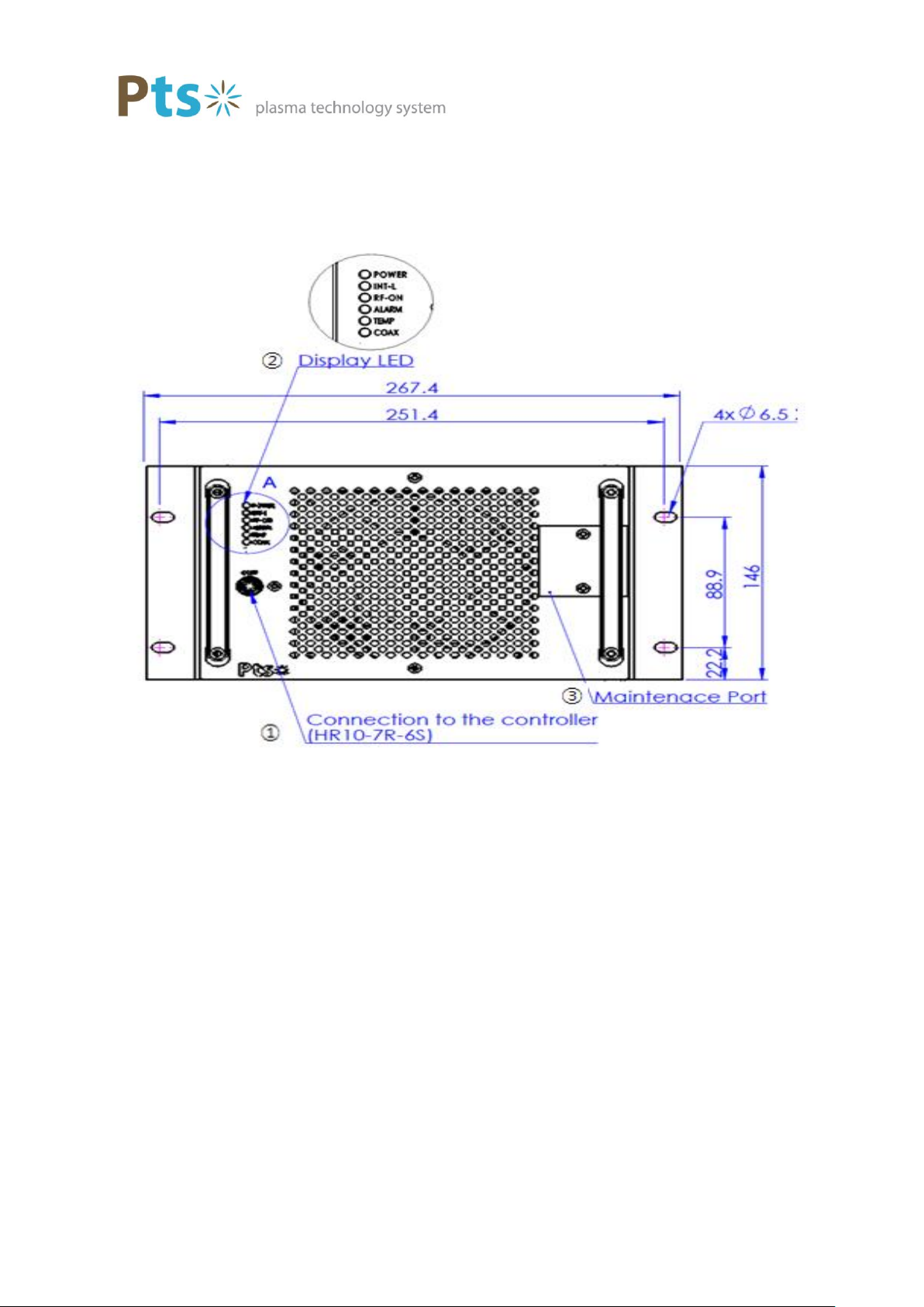
3. Dimensions

PTS-G5K13M PTS Co., Ltd. 9
PTS-G5K13M PTS Co., Ltd. 10
4. RF Generator System Overview
4-1 Front Panel
①Handy Ctrl
Connect the Handy Controller to set the operation of the Generator.
②Status Display LED
POWER It displays the main power input status. It lights when power is turned
on.
INT-L External interlock light turns on when normal.
RF-ON LED Light turns on when RF-On is on.
ALARM Light turns on when there is a warning.
TEMP Light turns on when high temperature reading is there.
COAX Light up when COAX cover removed.
PLUSE

PTS-G5K13M PTS Co., Ltd. 11
③Circuit protector Main Switch

PTS-G5K13M PTS Co., Ltd. 12
4-2 Rear
①Power Input Main power input (JL04HV-2E22-22PE-B)
②Water Cooling Water Cooling input (RC-3/8)
Water Cooling output (RC-3/8)
③Analog Interface D - SUB connector, 25P for the A / D Interface (XM2C - 2512)
④RF output connector ( 'HN' Type Female) & Connector cover
⑤Protection circuit circuit breaker
⑥D-Net D-Net Connector
5. Installation guide
There is a risk of electric shock. Please be careful when installing the items below.
PTS-G5K13M PTS Co., Ltd. 13
●Before connecting AC220V, turn of the power switch and circuit breaker.
●After the power switch and the circuit breaker is OFF, connect the coaxial cable to
the output terminal of the Generator.
●Make sure the cooling water is inflow before you switch on the RF power output.
5-1 Cable Connection
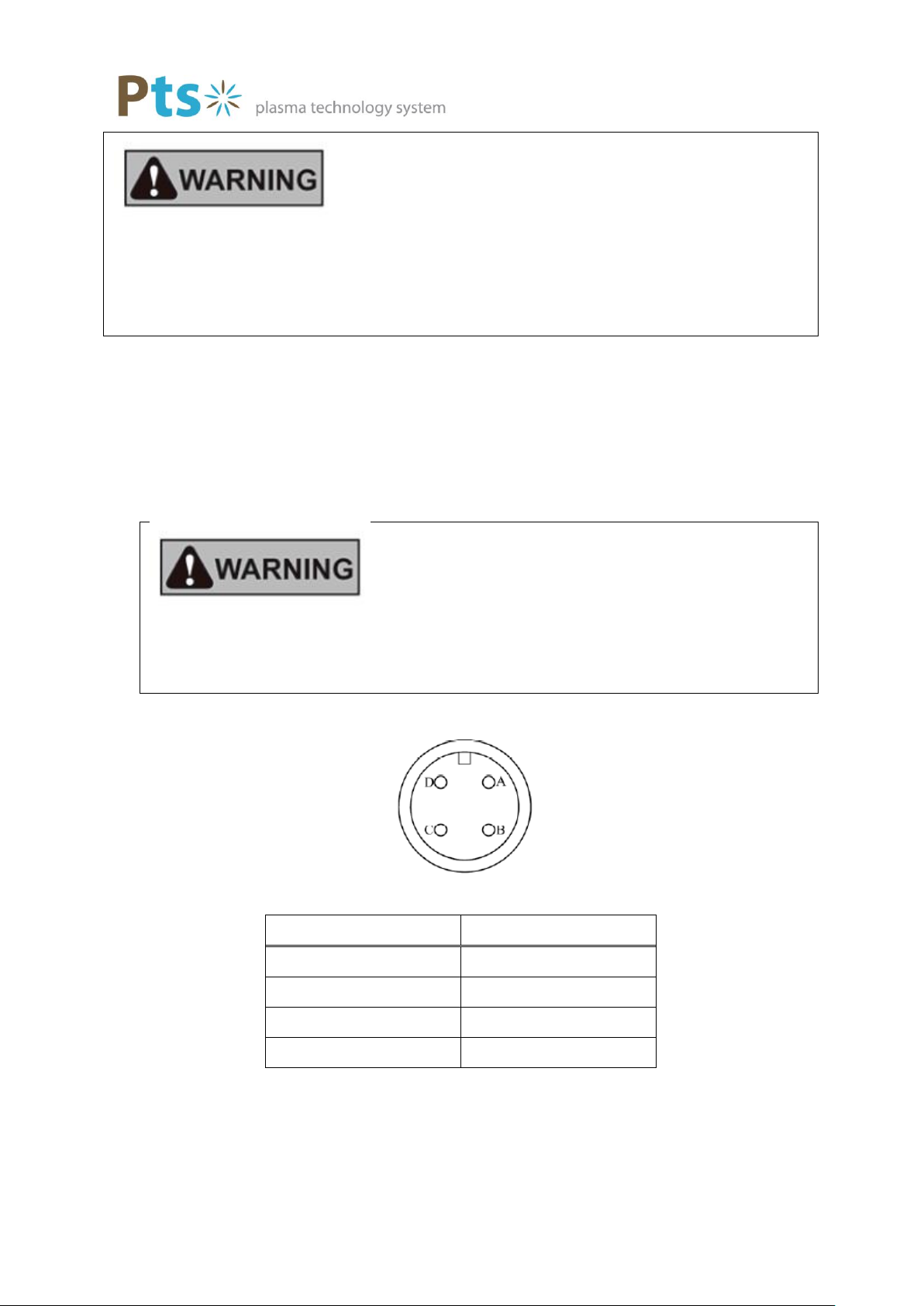
Power Connection
Always, turn Off power switch and circuit breaker of the power supply before connecting
the RF Generator.
There is a risk of electric shock; unless you connect the power cable is connected to
each phase and ground. Please check that it is properly connected.
Power Plug
Pin #
Phase
A
R
B
S
C
T
D
N
RF Connection
Make sure the power is switched OFF, the Matching Unit and Generator Output
is are connected using coaxial cable.

PTS-G5K13M PTS Co., Ltd. 14
Control Connection
Analog Interface (Analog Voltage Control)
Connect a Control Signal to the Analog Interface Terminal (D-Sub 25pin)
Confirm whether interface 3-5 connected to A/D interface(Pin assignment).
6. A/D Interface (Pin Assignment)
Pin No.
Name
I/O
Type
Function
1
RF-On,Off
Input
Contact
RF on/off(Max 5V 1mA)
2
INT-L
Input
Contact
Interlock(Max 5V 1mA)

PTS-G5K13M PTS Co., Ltd. 15
3
RF On Status
output
Analog
RF on Status(Max 30V 100mA)
4
ALARM
Output
Analog
ALARM(Max 30V 100mA)
5
INT/EXT STAT
Output
Analog
INT/EXT Status(Max 30V 100mA)
6
NC
7
RF Set
Input
Analog
RF Set Voltage(0~+10V=0~1000W)
8
Pf moni
Output
Analog
FWD Monitoring
Voltage(0~+10V=0~1000W)
9
NC
10
Pr moni
Output
Analog
REF Monitoring
Voltage(0~10V=0~1000W)
11
NC
12
NC
13
NC
14
D-GND
Input
Contact
RF-On Return
15
A-GND
Input
Contact
Interlock Return
16
A-GND
Output
Analog
RF-On Status Return
17
A-GND
Output
Analog
ALARM Return
18
A-GND
Output
Analog
Int/Ext Status Return
19
NC
20
A-GND
Input
Analog
RF-Set Return
21
A-GND
Output
Analog
FWD Monitor Return
22
NC
23
A-GND
Output
Analog
REF Monitor Return
24
NC
25
NC
※Please use D-GND and remove A-GND.
Analog Interface Connector Pin Functions
①RF On/Off (RF power On/Off Signal)
Pin 1,14 Open while RF off, and Close while RF On
②INT-L (Interlock Signal)
Pin 2,15 Open if no RF power, Close if there is RF power
PTS-G5K13M PTS Co., Ltd. 16
③RF On Status (RF Power Output Signal)
Pin 3,16 Open when the generator is in Idle, Close when RF Power is
applied/RF power on state /
④ALARM (Generator internal Alarm Signal)
Pin 4,17 Open when normal. Close when internal problem occurs
⑤INT/EXT Status (INT / EXT Signal state)
⑥RF Set (RF Power Set voltage)
Pin 7 (Set RF ) ) to a 0 ~ 10V, RF Output Power Set 0 ~ 3,000W to 20 ( A - GND ).
⑦Pf Moni(FWD Power Monitor)
7. Handy Controller
7-1 Handy Controller
Keep in mind that incorrect operation of Handy Controller may a cause problem.

PTS-G5K13M PTS Co., Ltd. 17
Display Area Liquid crystal display (W 62.0 × H 44.0), Resolution 128 × 64
Buttons A-D Buttons and mini tact switch are used. Key top is a panel
sheet film. Software determines operational functions.
Communication connector CONT: HR10-7R-6P –Connects with Matching Box
CONT connector.

PTS-G5K13M PTS Co., Ltd. 18
Operating Method
Status Display: The entry of the generator control signal or display monitor.
Button Function: Pressing A-D Buttons performs the function displayed next to
the corresponding button. Functions correspond to A-D
Buttons from top to bottom.
EXT : maintenance Mode (Analog I/O Control).
INT : Internal Control State.
RS232 : Communication Control
RF Output Monitor
Corresponding to A
Button
Corresponding to B
Button
Corresponding to C
Button
Corresponding to D
Button
Status Display
Status Display
Button
Function
PTS-G5K13M PTS Co., Ltd. 19
OPERATE
EXT
OPERATE ↑
QUIT
OPERATE MODE INT
A(YES) OR B(NO)
Control System
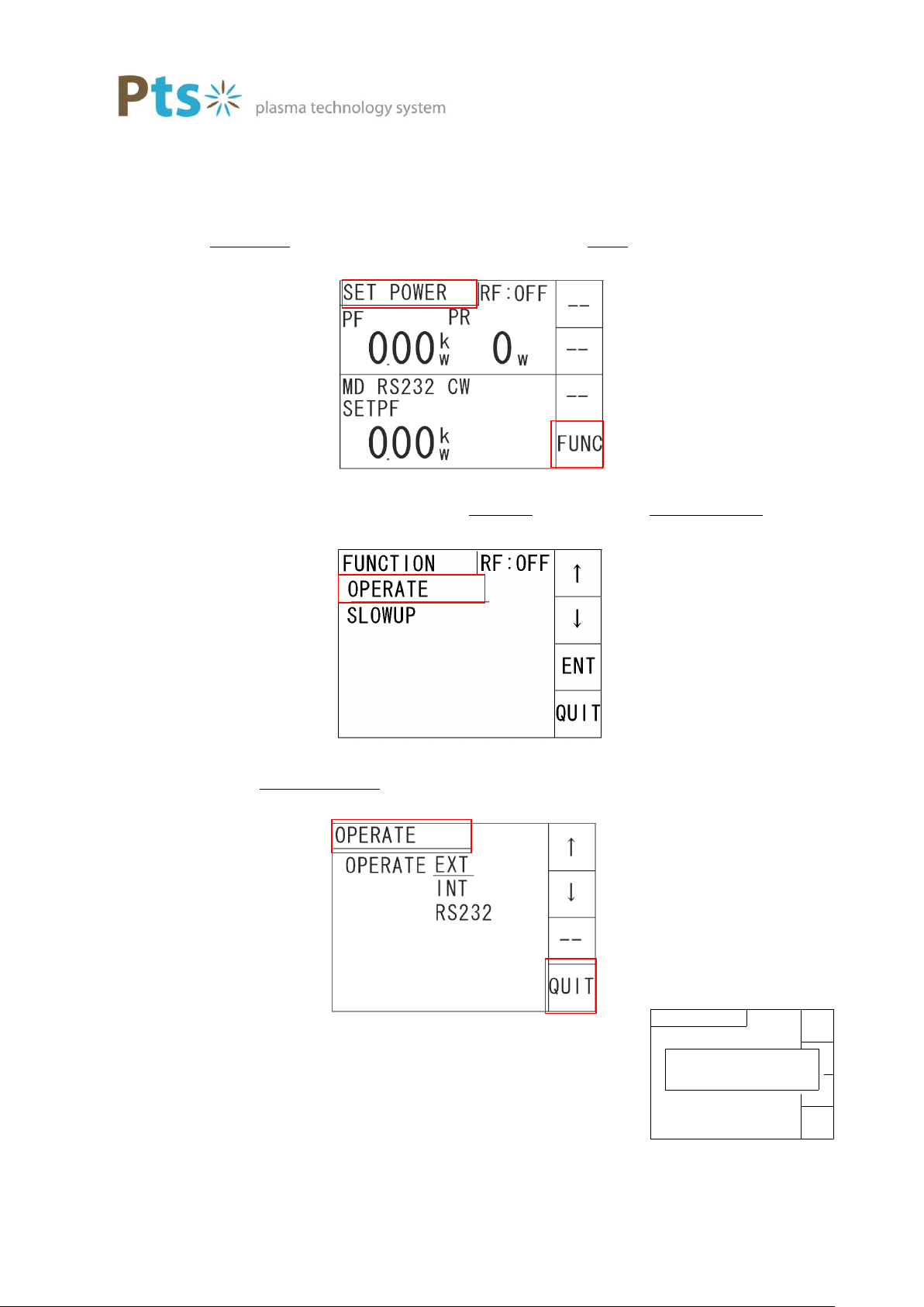
Caution! : Don’t change the settings while RF-ON
USET POWEr※1is displayed when you press D button [UFUNCU]※2(it goes to power
SETUP Screen)
※1 ①
※2 ②
In the function setting screen select [UOPERATEU]※3 to move to [UOperate] Screen
※3 ①
From [UOPERATE Screen] ※4, move the underscore to the item you want to select by
pressing [QUIT] ※5 (D Button).
※4 ①
※5 ②
※6 Confirm Screen
SET POWER 화면
①
②
FUNCTION 화면
②
①
OPERATE 화면
①

PTS-G5K13M PTS Co., Ltd. 20
RF-OFF
RF-ON
1000msec
7000w
0w
ス ロ ー ア ッ プ
→(t)
(定 格 )
Slow up time
Slow up settings to set up communication with the AC power during the initial values.
In the function setting screen, by selecting the [SLOWUP Screen] ※ 7 to move to [Slow up setup
screen ].
※7 ①
Slow up, down setting , can be operated using A button [↑ ] and B button [ ↓ ] ※8.
↑:Press once to increase the setting to 50
↓:Press once to decrease the setting to 50
(It is set in the range of 300msec~5000msec)
※8 ①
After setup is completed, it can be set by pressing the [QUIT] (D button). ( A
Function Setting Screen
①
Slow up, down Setting Screen
①
1000msec Setting
Slow up
Rating
Table of contents
Other Pts Portable Generator manuals


Popular Portable Generator manuals by other brands

Generac Power Systems
Generac Power Systems PowerBOSS Contractor 1648-0 owner's manual

Powermate
Powermate Pulse Series Operator's manual

Schmalz
Schmalz ECBPMi UR operating instructions

Gage Bilt
Gage Bilt GB808V Original instructions

Briggs & Stratton
Briggs & Stratton 30246 user manual

Powerhorse
Powerhorse M750139B.2 owner's manual


