Pubert Honda GCV 160 Manual
25241
DATE OBJET MACHINE CONCERNÉE FICHE N°
DATE PURPO E MACHINE CONCERNED HEET NO
01/02/02 2003/013
Kit r mplac m nt poigné à dépr ssion
R plac m nt kit for vacuum l v r
TOUTES LES MOTOBINEUSES DE RODUC-
TION UBERT A ARTIR DU 09 / 2000
ALL THE TILLERS OF UBERT RODUC-
TION FROM 09 / 2000
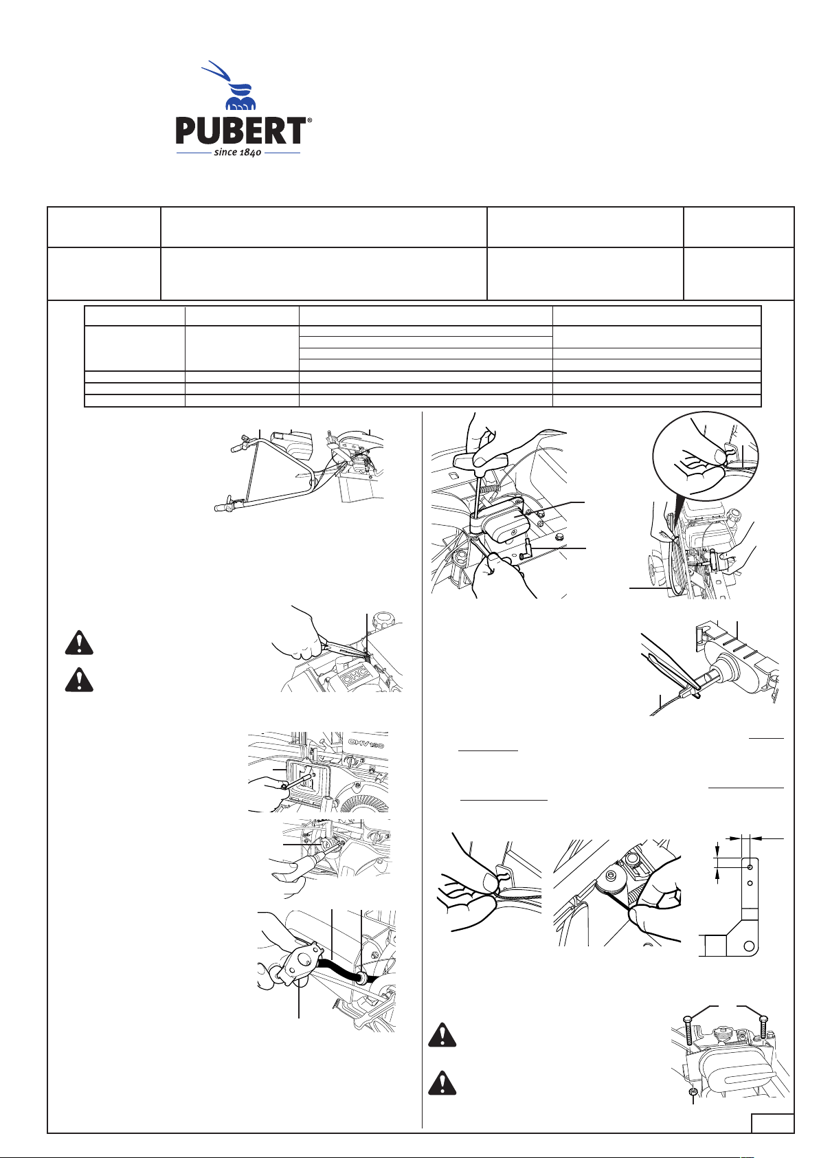
1• Déposer le guidon (1) et
les carters (2 et 3).
Remove the handlebars
(1) and fairings (2 and 3).
3• Déposer la courroie (10), câble (11) et le verin (12). Supprimer le
coude (13).
Take off the belt (10), cable (11) and cylinder (12). Discard the angle
bracket (13).
2• Remplacer le tuyau d’aspiration (4) par le nouveau en supprimant
le clapet anti-retour.
Replace the air inlet tube (4) with the new one; do not re-use the non-
return valve. 4• Repositionner le câble (11) sur la
tige du nouveau vérin (14).
Reposition the cable (11) on the stem
of the new cylinder (14).
1 2 3
V rsion Honda GCV 160
Vérifier l’étanchéité entre le tube
et la cale thermique.
Check that there is no leakage bet-
ween the tube and the thermal block.
4
V rsion Briggs & Sratton 5,5HP - OHV
A - Dévisser le carter et enlever le
filtre. Démonter le support filtre
(5).
A - Unbolt the fairing and remove the
filter. Dismantle the filter bracket
(5).
5
B - Démonter le carburateur (6).
B - Unbolt the carburettor (6).
6
C - Dégager la pièce du carbura-
teur (7), enlever le clapet anti-
retour (8) et remplacer le tuyau
d’aspiration (9). Remonter l’en-
semble filtre.
C - Release the carburettor piece (7),
remove the non-return valve (8)
and replace the air inlet tube (9)
with the new one. Reassemble the
carburettor and filter assembly.
7
8
9
13
12
11
10
11
14
7
10
5• Mettre l’extrémité du câble dans le trou supérieur du levier, bi n l
positionn r dans la gorge du galet de renvoi. Si trou non existant,
le réaliser (Ø5,5) suivant le croquis ci-dessous.
Place the end of the cable in the upper hole of the lever, making sure it is
properly positioned in the groove of the return pulley. If there is no hole
in the lever, drill one (diameter 5.5 mm) as shown in the diagram below.
Remonter la courroie - Replace the belt
6• Fixer le vérin à l’aide des 2 vis (15).
la vis la plus longue à l’arrière. Enlever la
peinture sous l’écrou (16).
Bolt the cylinder in place using the two screws (15)
The longer screw goes at the back. crape off
the paint from under the nut (16).
15
16
Coloris / Colour Référence / Reference Type de moteur / Type of engine Tube fournie / Tube supplied
Jaune - Yellow 12101150 Honda GCV 160 14328 - Ø3,5x8,4 - lg 435
Briggs & Stratton 3,5 - 5H
Briggs & Stratton 5,5H Intek OHV 14320 - Ø4,7x9,5 - lg 200
Robin EY20 Non fourni - Not supplied
Rouge - Red 12102150
Bleu - Blue 12103150
Orange - Orange 12104150
Note d’information technique
Technical information
25241
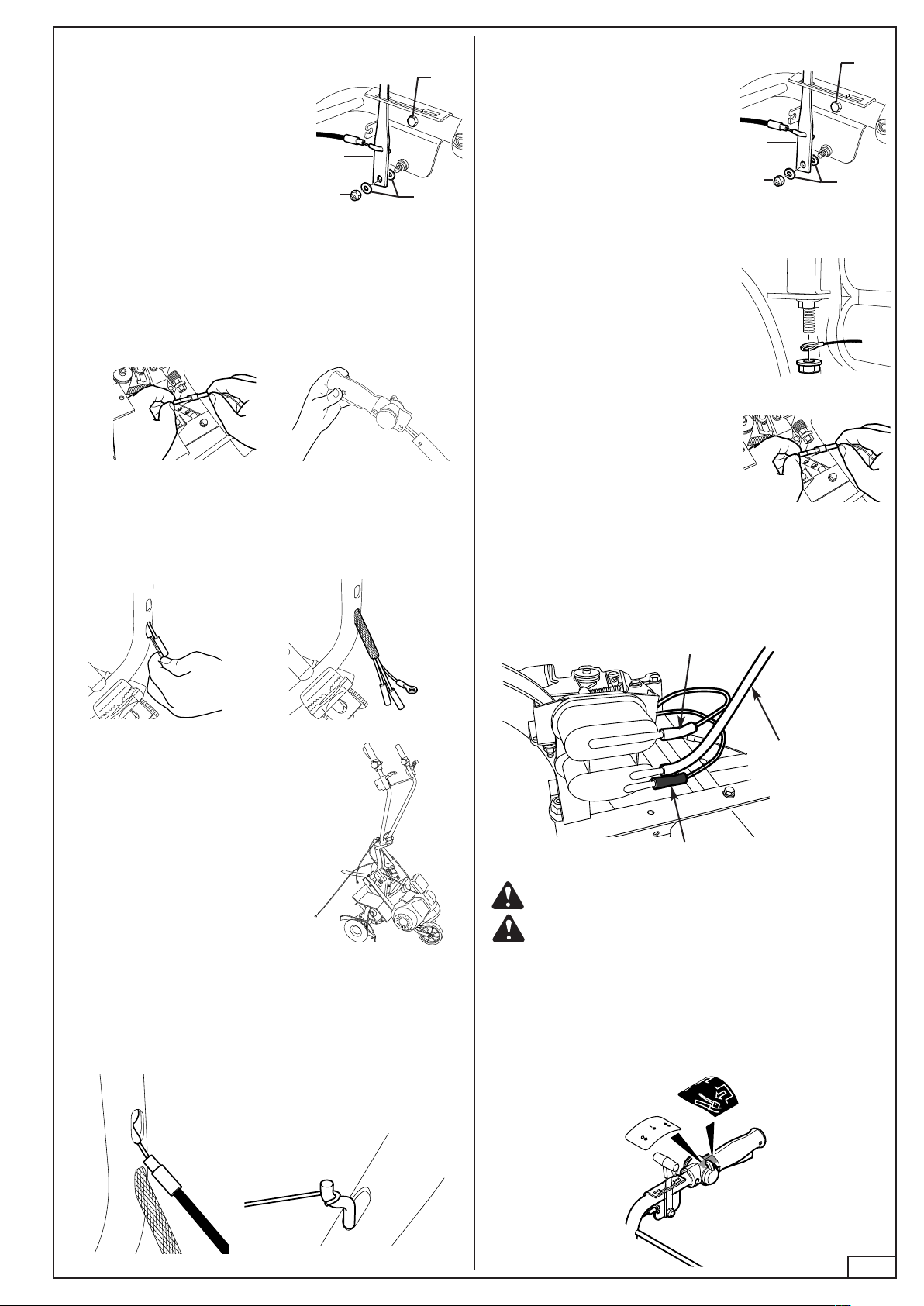
8• Après avoir enlevé les 2 vis de la poignée d’embrayage et débran-
cher le fil d’arrêt (fig. A), retirer l’ensemble poignée/faisceau (fig.
B), le remplacer par la nouvelle poignée.
Remove the two retaining screws from the clutch handle and unfasten the
stop wire (fig. A). Remove the complete handle and wiring assembly (fig.
B) and replace them with the new set.
7• Démonter la vis (17) de la poignée
inverseur, l’écrou (18) et les rondelles
(19). Retirer le câble par le bas du gui-
don après l’avoir déconnecté du levier
(20), et enlever l’ensemble poignée
inverseur.
Unscrew the bolt (17) of the reversing
lever, then the nut (18) and the washers
(19). Disconnect the cable from the lever
(20) and withdraw it from the bottom of
the handlebars. Remove the reversing
lever assembly.
17
18 19
20
17
18 19
20
Fig. B
Fig. A
9• À l’aide d’une pointe fine récupérer l’extrémité des 2 raccords du
faisceau et du fil de masse par le trou le plus bas.
Using a thin point, pull out the end of the tubes and the earth wire through
the lower hole.
10• Remonter le guidon et basculer
la machine vers l’avant.
Reassemble the handlebars and tilt
the whole machine forwards.
11• Remettre les 2 vis de fixation de la nouvelle poignée. Engager le
câble d’inverseur dans le 2ème trou du bas du guidon (Fig. A) et le
récupérer en haut à l’aide d’un crochet (Fig. B).
Replace the two retaining screws in the new handle. Push the reversing
cable in through the other hole at the base of the handlebars (fig. A).
and hook it out through the top hole (fig. B).
Fig. A Fig. B
12• Raccrocher l’extrémité du câble sur le
levier (20), visser l’écrou (18) d’un ou
deux tours avec les deux rondelles
(19) et positionner le câble dans la
butée de gaine. Bloquer la vis (17) et
serrer modérément l’écrou (18).
Re-attach the end of the cable to the
lever (20), put the washers (19) in place
and give the nut (18) one or two turns.
Position the cable in the sheath stop,
then tighten screw (17) and moderately
tighten the nut (18).
13• Basculer la machine en position de
travail. Rebrancher le fil de masse
sur la vis arrière du vérin et le blo-
quer avec l’écrou.
Lean the machine back into its working
position. Connect the earth wire to the
rear screw on the cylinder and fix in
place with the nut.
14• Connecter le fil de contacteur d’arrêt
coté moteur.
Connect the wire of the stop contact to
the engine.
15• Branchement du tuyau d’aspiration sur le vérin. Tuyaux venant
de la poignée (embout blanc en haut et embout noir en bas).
Plug the vacuum tubes from the handle onto the cylinder. The white
connector goes on the top and the black one on the bottom.
Bi n l s nfoncés pour évit r l s pris s d’air.
Push the connections well home to ensure they are airtight.
Embout noir
Black connector
Aspiration
mot ur
Engine connection
Embout blanc
White connector
16• Remonter les 2 capots et coller les autocollants 62831a et
14678b sur la poignée d’embrayage.
Replace the two fairings and stick the labels 62831a and 14678b on
the clutch handle.
Popular Engine manuals by other brands


Weber Automotive
Weber Automotive MPE 750 Turbo Marine Service manual

Mercury Racing
Mercury Racing 1550 STERNDRIVE OPERATION, MAINTENANCE & WARRANTY

Kohler
Kohler KD425-2 Workshop manual

Lenze
Lenze M Series manual

Barrus
Barrus Shire 15 15 CB manual

Aerotech
Aerotech RMS 98/10240 BLACK MAX Assembly and operation instructions