10 of 10
INSTALLATION
7650 - L9 IG - INST
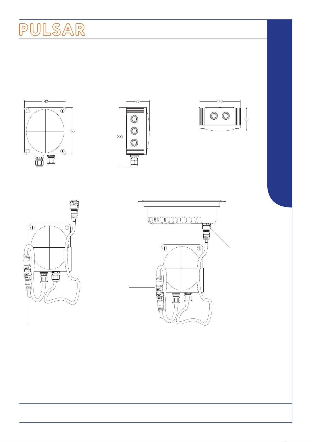
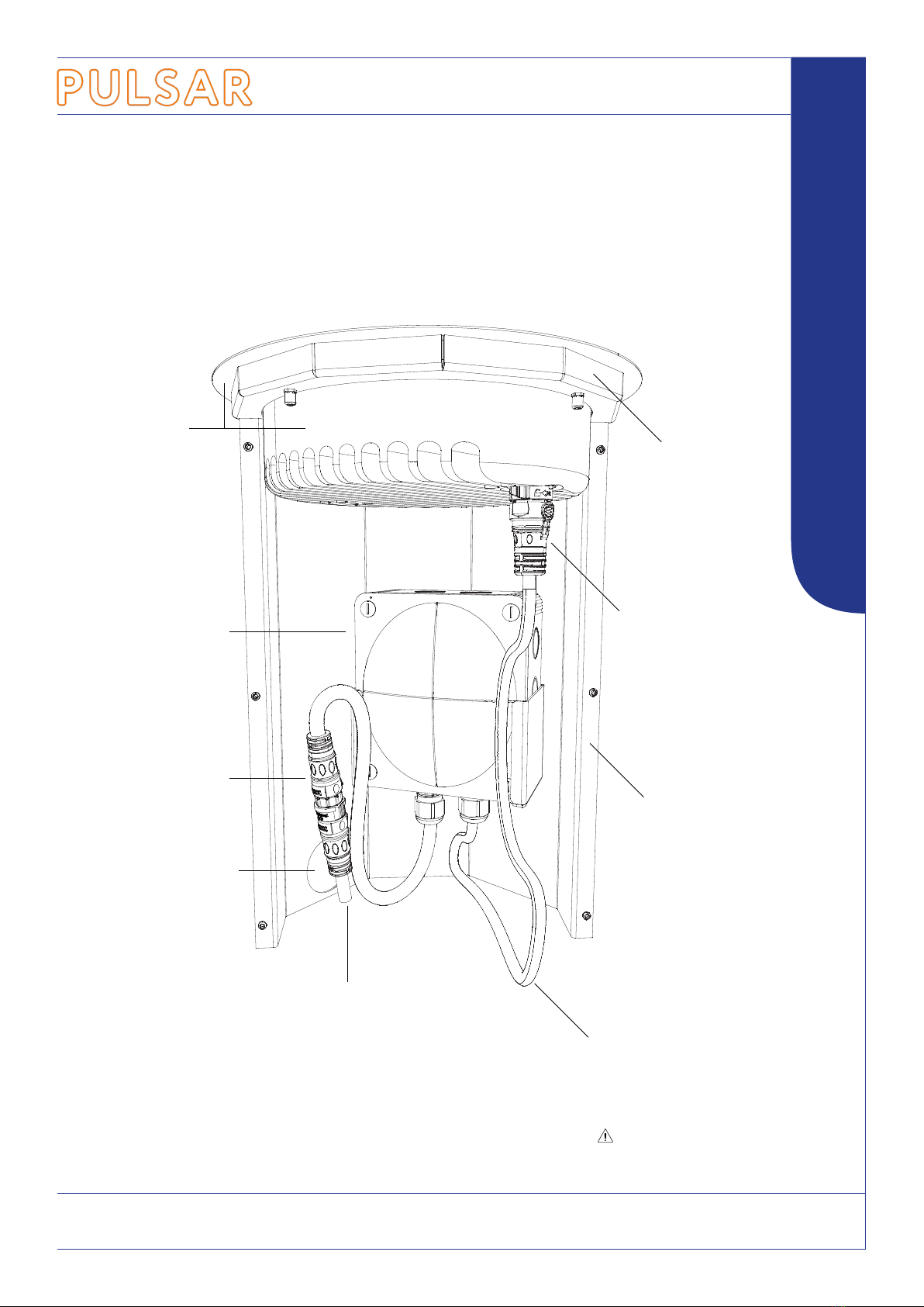
LUXEOS RANGE INGROUND
ADDITIONAL INFORMATION
Power Requirements
LuxEOS Flood 9 Inground 120 -277V AC @ 50/60Hz 50W
Product Weights
LuxEOS 9 Inground Luminaire 3.9 kgs
LuxEOS 9 Inground Driver 1.1kgs
LuxEOS 9 Inground Ground Mount 4.5kgs
QuickLINK+ Cable Colours (Power)
Green Earth - Ground
Black Live Phase
White Neutral
QuickLINK+ Cable Colours (Data in)
White DMX +
Green DMX -
Shield Screen
QuickLINK+ Cable Colours (Data through)
Red DMX +
Blue DMX -
Shield Screen
DMX Cable Colours (Pulsar)
White DMX +
Blue DMX -
Shield Screen
Mains Supply Cable Colours (Harmonised)
Green/Yellow Earth - Ground
Brown Live Phase
Blue Neutral
LUXEOS 9 Inground VIVID COLOUR & TUNABLE WHITE
LED INGROUND FLOOD FOR ARCHITECTURAL LIGHTING
Portable Appliance Testing
LuxEOS luminaires may be safely earth bond and insulation tested (500V).
September 2021
Mechanical Ratings
Ingress Protection IP67 LuxEOS 9 Inground luminaire & driver
Impact Protection IK10 LuxEOS 9 Inground luminaire
Static Load 3000kgs LuxEOS 9 Inground luminaire
Maintenance
LuxEOS luminaires should be regularly tested and inspected, and as part of this checked for the build up of external moss and debris which can reduce the
light output. If cleaning is required, then a mild water based detergent should be used, care should be taken to avoid the use of harsh solvent based cleaning materials as
this could result in damage to the luminaire. Under no circumstances should pressure washers be used for cleaning.
The light source contained in this luminaire shall only be replaced by Pulsar or an authorised service agent or a similar qualied person.
As part of our commitment to continuous improvement PULSAR may change the specications of its products without prior notication or public announcement.
All descriptions, illustrations, drawings and specications in this publication present only general particulars and shall not form part of any contract.
Please visit our website for the most up to date information.
Warranty
Five years from the date of original purchase.
The warranty covers defects in manufacturing workmanship and materials. It is limited to parts and labour.
The warranty becomes void if the product is :-
A Misused.
B Not used in accordance with the instructions.
C The cable connections are not made according to our instructions if the unit is used in damp or wet environments.
D Repairs are made by unauthorised persons.
E The serial number label has been removed or defaced.
Pulsar’s maximum liability shall not exceed the price paid for the product.
In the unlikely event of a fault occurring, do not use without repair, return the product, with a description of the fault, to your supplier or direct to Pulsar for immediate attention.
Full warranty details are available on request or from our website at www.pulsarlight.com.
Standards
LuxEOS luminaires conform to the following standards and certication.
UKCA WEEERoHSEuropean CE
P U L S A R
Part of DW Windsor Ltd, Pindar Road, Hoddesdon, Hertfordshire, EN11 0DX, UK