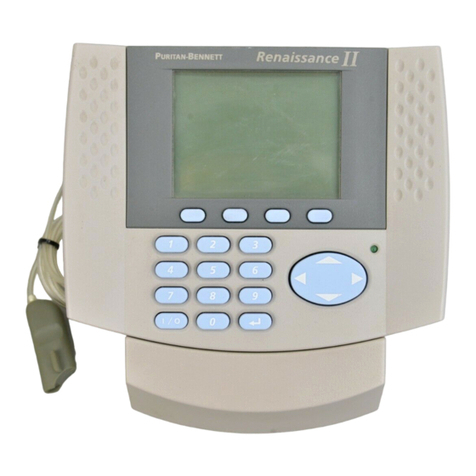
Puritan Bennett GoodKnight 425 User manual

GoodKnight®425
SERVICE MANUAL
GoodKnight®425ST
P/N: M-145MAT00-20 Revision A


This document is the property of NELLCOR PURITAN BENNETT, Inc and is distributed on the express condition that
it is neither divulged nor reproduced in part or in full by anyone other than NELLCOR PURITAN BENNETT, Inc with-
out prior written agreement, and no right is granted to divulge or use any information contained in this document.
ãCopyright NELLCOR PURITAN BENNETT, Inc - 2004
ALL RIGHTS RESERVED
GoodKnight 425 / 425ST Service Manual
P/N: M-145MAT00-20 Rev. A - Page Rev.A 1

PREFACE
This manual provides information necessary to service the GoodKnight 425 and the GoodKnight
425ST Respiratory System. This information is intended for use by technicians or personnel quali-
fied to repair and service medical equipment. The information is not exhaustive and may not be ap-
plicable to future models.
DEFINITION OF STATEMENTS
Statements in this manual preceded by the followings words are of special significance.
WARNING
Means there is the possibility of injury or death to yourself or others.
NOTE
Indicates points of particular interest for more efficient and convenient operation.
CAUTION
Means there is the possibility of damage to the GK 425/425ST unit or other property.
GoodKnight 425 / 425ST Service Manual
P/N: M-145MAT00-20 Rev. A - Page Rev.A 2

REVISION LIST OF
GoodKnight 425 / 425ST Service Manual
This list of effective pages represents manual P/N M-145MAT00-20, revision A.
Revision Description Date
A
05/2004
Effective Pages Revision Effective Pages Revision
All pages A
Initial Release.
GoodKnight 425 / 425ST Service Manual
P/N: M-145MAT00-20 Rev. A - Page Rev.A 3
Federal law restricts this device for sale by or on the order of a physician.

GoodKnight 425 / 425ST Service Manual
CONTENTS
PREFACE 2
REVISION LIST 3
I - GENERAL INFORMATION I-1
A. SPECIFICATIONS I-2
1) Performances I-2
2) Electrical specifications I-2
3) Environmental specifications I-3
4) Physical specifications I-3
5) Pressure stability I-3
6) Dynamic resistance I-4
B. USING A HUMIDIFIER I-4
C. SYMBOLS I-5
D. CLEANING INSTRUCTIONS I-6
1) GoodKnight 425 / 425ST I-6
2) Air filter I-6
E. DISPOSAL OF THE DEVICE AT THE END OF ITS LIFETIME I-6
II - THEORY OF OPERATION II-1
A. GENERAL DESCRIPTION II-2
1) General design synopsis II-2
2) View of the control panel II-2
3) Description II-3
4) Inspiratory/Expiratory sensitivity II-3
5) Temperature Sensor II-4
6) Rise Time II-4
7) Pneumatic Diagram II-4
P/N: M-145MAT00-20 Rev. A - Page Rev.A 4

GoodKnight 425 / 425ST Service Manual
P/N: M-145MAT00-20 Rev. A - Page Rev.A 5
B. ELETRICAL DIAGRAM II-5
1) General Block diagram II-5
2) Micro-controller II-6
3) Pressure measurement chain block diagram II-7
4) Flow measurement chain block diagram II-7
5) Temperature measurement II-8
6) Serial Link II-8
III - SERVICE AND REPAIR III-1
A. PERFORMANCE VERIFICATION III-3
1) General information III-3
2) Frequency III-3
3) Equipment required III-3
4) Preparation for testing III-4
5) Verification with computer III-5
5-a) Preparation III-7
5-b) Pressure verification and calibration III-7
5-c) Verification of the Flow measurement chain III-8
5-d) Verification of the ramp III-9
5-e) Verification of the backup frequency (425ST only) III-9
6) Performance Verification with keypad III-10
6-a) Verification of the pressure without computer III-10
6-b) Ramp verification III-12
6-c) Verification of the backup frequency (425ST only) III-13
7) Configuration with factory settings III-14
8) Entering the serial number and hour meter values III-15
9) “Service” hour meters III-15
10) Setting the Clock with keypad III-16
B. CALIBRATION PROCEDURE III-18
1) Equipment required III-18
2) Pressure sensor calibration III-19
3) Flow sensor calibration III-20
C. DISASSEMBLY III-22
D. TROUBLESHOOTING GUIDE III-20
Information Messages III-21
E. ERROR MESSAGES III-26
¨HISTORY RECORD FORM III-27
IV - SPARE PARTS IV-1

GoodKnight 425 / 425ST Service Manual
P/N: M-145MAT00-20 Rev. A - Page Rev.A 6

I - GENERAL INFORMATION
GoodKnight 425 / 425ST Service Manual
P/N: M-145MAT00-20 Rev. A - Page Rev. A I-1

GoodKnight 425 / 425ST Service Manual
P/N: M-145MAT00-20 Rev. A - Page Rev. A I-2
A. SPECIFICATIONS
1) Performances
GoodKnight 425 and GoodKnight 425ST
ÄPressure adjustment range
IPAP: 3 to 25 cmH2O in 0.5 cmH2O increments
(see note 1)
EPAP: 3 to PIP (maximum 20 cmH2O)
ÄPressure setting accuracy: ± 0.5 cmH2O (see note 2)
ÄFlow range 0 to 90 l/min @ 3 to 25 cmH2O
(while maintaining pressure setting accuracy)
ÄRamp (adjustable) disabled, or 5 to 30 min in 5 min increments
ÄRise Time (rt) 1 to 5 in 1 increment
ÄExpiratory / Inspiratory sensitiviy 1 to 10 in 1 increment
GoodKnight 425ST only
ÄBackup Frequency Disabled (0) or activated 4 to 25c/min
ÄI/E ratio 1:4.0 to 1:0.5 in 1:0.5 increment
ÄSetting restrictions: The maximum duration of the IPAP pressure is limited to 3 sec-
onds. Consequently certain combinations of frequency, rise time and I/E ratio will be
forbidden, especially for low frequency setting.
As well, certain combinations of frequency, rise time and I/E ratio which prevent the
IPAP set pressure to be reached will be forbidden, especially for high frequency setting.
NOTE 1
The display can be in “hPa”. The pressure adjustment range is then between 2.9 hPa
and 24.5 hPa. To select the unit, unplug the device, depress the hidden key and recon-
nect the device, keeping the hidden key depressed until the unit is displayed.
NOTE 2
All the stated performances are for a 6 ft (1.80-meter) patient circuit, recommended by
the manufacturer, fitted with a stopper with a 4 mm diameter leak.

GoodKnight 425 / 425ST Service Manual
P/N: M-145MAT00-20 Rev. A - Page Rev. A I-3
2) Electrical specifications
Power supply
ÄExternal Power Supply Class II 100-240 VAC 50/60 Hz—13VCC 4A
Goodknight
ÄConsumption 40 VA max.
ÄCurrent consumption 1.1A @ 25cmH2O with 4 mm leak
3) Environmental specifications
ÄStorage / Transport temperature -20° C to 60° C
ÄStorage / Transport humidity up to 95 % (non-condensing)
ÄOperating temperature +5° C to +40° C
ÄOperating humidity between 15 % and 95 % (non-condensing)
ÄOperating relative pressure 700 hPa to 1060 hPa (approximately up to
altitude of 7874 ft -2.400 m)
4) Physical specifications
ÄWidth 5.6” (144 mm)
ÄHeight 2.9” (79 mm)
ÄLength 7.7” (198 mm)
ÄWeight (without external power module) 1.58 lbs (780 g)
5) Pressure stability (static mode)
The measured pressures are the pressures measured under a positive airflow continuous of
100 l/min. These measurements were made with a single unit.
Set Pressure
(cmH2O)
Measured Pressure
(cmH2O)
4 3.8
8 7.8
12 11.7
20 19.9

GoodKnight 425 / 425ST Service Manual
P/N: M-145MAT00-20 Rev. A - Page Rev. A I-4
6) Dynamic resistance
The values below were measured from a simulated sinusoidal respiratory signal with a tidal volume
of 500 ml after a warm-up period of 2 hours. These measurements were made with a single unit.
B. USING A HUMIDIFIER
A heating or non-heating humidifier may be used with the GoodKnight 425 / 425ST on the
condition that the following warnings are noted.
WARNING
You are strongly advised to read the manufacturer’s recommendations for the humidi-
fier before use.
WARNING
Using a humidifier can alter the performance of the GoodKnight 425 / 425ST.
WARNING
The GoodKnight 425 / 425ST must always be placed above the humidifier. This position
will minimize the potential for water entering the Cpap device.
Water can damage the device.
Pre ssure @ Fre que ncy Variation in pressure
(CmH2O)
Variation in airflow
(l/s)
Dynamic resistance
(CmH2O/l/s)
7cmH2O @ 10c/min 0,28 0,66 0,42
7cmH2O @ 15c/min 0,37 0,98 0,38
7cmH2O @ 20c/min 0,58 1,28 0,45
14cmH2O @ 10c/min 0,38 0,70 0,54
14cmH2O @ 15c/min 0,43 1,03 0,42
14cmH2O @ 20c/min 0,64 1,33 0,48
20cmH2O @ 10c/min 0,58 0,88 0,58
20cmH2O @ 15c/min 0,50 1,07 0,47
20cmH2O @ 20c/min 0,64 1,26 0,51

GoodKnight 425 / 425ST Service Manual
C. SYMBOLS
P/N: M-145MAT00-20 Rev. A - Page Rev. A I-5
SYMBOLS DEFINITIONS
Alternating current
Direct current
Class 2 Equipment
Type B
Warning ! Consult instructions
before using this unit.
On / Off
Access to settings
Ramp
RS 232
Increase or decrease the adjust-
ment values
Device protected against the ver-
tical falls of water drops.
Federal law restricts this device for
sale by or on the order of a physi-
cian. (US Only)
Input DC voltage 13 V
Patient Output
Device complies with the require-
ments of the Standard CSA C22.2
Nr 601-1. (Canada)
~
Rx ONLY

GoodKnight 425 / 425ST Service Manual
D. CLEANING INSTRUCTIONS
1) GoodKnight 425 / 425ST
Frequency As necessary
How to clean Wipe with damp cloth moistened with warm, soapy water.
Wipe dry.
2) Air filter
Frequency Inspect the air filter frequently by removing it from the back panel.
Clean at least once a week or more often, if necessary.
How to clean Wash in warm, soapy water. Rinse thoroughly to remove all soap.
Pat dry with towel. Allow to air dry completely before reinstalling.
Replace filter if worn or damaged.
E. DISPOSAL OF THE DEVICE AT THE END OF ITS LIFETIME
In order to preserve the environment, the various parts of the device and its accessories must
be disposed of at approved waste sites in accordance with current regulations.
WARNING
Unplug the unit from all electrical power sources before cleaning. Do not allow
water to enter the unit through any opening.
CAUTION
Only the standard air filter can be cleaned. The fine filter supplied as an option and
fitted in addition to the standard air filter, cannot be cleaned. It must be changed.
P/N: M-145MAT00-20 Rev. A - Page Rev. A I-6

II - THEORY OF OPERATION
P/N: M-145MAT00-20 Rev. A - Page Rev.A II-1
GoodKnight 425 / 425ST Service Manual

A. General description
1) General design synopsis
P/N: M-145MAT00-20 Rev. A - Page Rev.A II-2
2) View of the control panel
Ramp activation or
Parameter settings
Hidden Key
LCD Display
On/Off
or
Parameter settings
Information
Access button
GoodKnight 425 / 425ST Service Manual
Current
Alarm Current
Flow direct
Flow filtered
Bus // Bus I2C
Current filtered
Fl
ow
Pressure filtered
ErrorMotor
BusyI2CMaster
Bus
y
I2CMoto
r
Backlight
Set-up
Battery
Microcontroler
C508
Motor driver
Power
Driver Blower
o
tection
l
terin
g
u
lation 5V Current
Measurement
Pressure
Sensor
RTC +
RAM 56 octets
Patien
t
Interfa
c
Air
Input
Power AC
n
al Module
C
/DC
le LCD
yp
ad
a
l Link
Microcontroler
C508
Master
RAM
64 ko
O
M
4
ko
Flow
Sensor
Voltage
Reference
Con troler of
NVRAM
Watchdog
Reset
Motor Reset
Set Change
Type cycle
Respiratory phase
C
T
N
Temperature Blower
WDI C
E
Slope
External Module
AC/DC
Protection
Filtering
Regulation
5V
Main Power AC
LCD Module
Keypad
Serial Link
ROM
64K
P
i
t
o
t
Patient
Inte rface

3) Description
The general architecture of the device is based on the use of a blower (pressurised air genera-
tor) and two micro-controllers (one for the general functions of the unit and another one for
the motor control).
Some functions are hardware-controlled, some are software-controlled and others are a mix-
ture of hardware and software.
The GoodKnight 425 BiLevel is a BiLevel positive airway pressure device used in the treat-
ment of obstructive sleep apnea or for the titration in the sleep lab of a patient having obstruc-
tive sleep apnea. It is intended to treat OSAS patients who are over 30 kg in weight (66
pounds).
In the BiLevel mode the GoodKnight 425 tracks patient breathing cycles and, in response to
the patient’s inspiratory and expiratory efforts, provides two levels of pressure :
-IPAP : a higher level of pressure for inspiration (a range from EPAP to 25 cmH2O)
-EPAP : a lower pressure for expiration (a range from 3 to IPAP or 20 cmH2O).
-If IPAP is equal EPAP, than the unit operates in CPAP mode.
The GoodKnight 425 BiLevel is a microprocessor-controlled pressure generator capable of
controlling the pressure delivered to the patient. Among its operating features are:
* GK425ST in CPAP, BiLevel with and without backup frequency
* GK425 in CPAP, BiLevel without backup frequency.
* Monitors pressure, respiratory rate, I/E ratio and compliance.
* Adjusts inspiration and exhalation flow-triggered sensitivity independently to provide
precise patient comfort.
* Provides a maximum pressure setting of 25 cmH2O
* Compensates automatically for altitude and for leaks up to a total flow rate of 120 liters
per minute, on top of the usual 4mm non re-breathing leak at 20 cmH2O.
The GoodKnight 420 Series benefits from a new blower technology that is specifically
designed for this range of Cpap systems. This design provides optimum performances in
terms of size, consumption, noise and stability.
In order to guarantee these optimum performances, some parameters are electronically
tuned during the manufacturing process. These parameters are calculated for each
blower and cannot be duplicated for another one. For this reason it is not possible to
change a blower or an electronic board. In the event of failure, an internal chassis as-
sembly fitted with a factory-set blower and electronic board is available.
P/N: M-145MAT00-20 Rev. A - Page Rev.A II-3
4) Inspiratory and Expiratory sensitivity
The trigger of sensitivity can be set with a scale of 1 to 10.
1= The lower triggering level = The highest sensitivity,
10=The highest triggering level = The lower sensitivity.
GoodKnight 425 / 425ST Service Manual

7) Pneumatic diagram
P/N: M-145MAT00-20 Rev. A - Page Rev.A II-4
5) Temperature Sensor
The stator of the blower is fitted with a temperature sensor which will protect the system
against the overheating of the blower in the eventuality of a problem.
The GoodKnight BiLevel will stop working if the temperature goes above 95°C +/-5°C during
10 seconds.
6) Rise time (rt)
The rise time between EPAP and IPAP can be set from about 300ms/ 10 cmH2O to about
600ms/10 cmH2O. This rise time is adjustable on a scale of 1 to 5:
1 ~ 300ms / 10cmH2O
2 ~ 375ms / 10cmH2O
3 ~ 450ms / 10cmH2O
4 ~ 525ms / 10cmH2O
5 ~ 600ms / 10cmH2O
GoodKnight 425 / 425ST Service Manual
DC Motor
Blower
Impeller
Sensor
Humidifier
(optional)
Nasal mask
or
Flow
Output
connector
nasal pillows
Patient
tube
Inlet filter
Pressure sensor
tube
Pressure Sensor
Pitot Tube
Electrical system
Air

B. ELECTRICAL DIAGRAM
1) General block diagram
P/N: M-145MAT00-20 Rev. A - Page Rev.A II-5
GoodKnight 425 / 425ST Service Manual
Case
Main Power
AC
13Vcc-4A
Serial Link
1.1.2 Power Supply
1.1.3 AC
External Power Supply
External Module
AC/DC
100 – 264 Vac
1.1.1.1 13Vcc / 24W
Interface
Serial Link
Protection
and
Filtrage
Moteur Driver
Blower
Electronic
Regulation
5V
Air
Input
Case GK420
Isolation
Barrier
4kV
Pressure
Sensor
Pressure
Sensor
Pitot
tube
PATIENT
Flo w
Sensor

2) Micro-controller unit block diagram
a) Micro-Master
P/N: M-145MAT00-20 Rev. A - Page Rev.A II-6
b) Micro-Motor
GoodKnight 425 / 425ST Service Manual
Motor
Bridges
MOSFET
Interfaces
µC
MOTOR
P12/CC0
P13/COUT0
P14/CC1
P15/COUT1
P16/CC2
P17/COUT2
Data
Memory
SRAM
64 ko
CS
WE
OE
µC
MASTER
P51
Reset
WR
RD
Vcc
A15
A8
AD7
AD0
ALE
Software
Memory
ROM
64 ko
CS
G
A0-7
AD0 – 7
D0 – 7
Multiplexer
MAX691
WDI
Reset
This manual suits for next models
1
Table of contents
Other Puritan Bennett Medical Equipment manuals