PURSUIT 123 User manual

Provider:
Détaillant:
Proveedor:________________________________________________________________________
Address:
Adresse:
Dirección:________________________________________________________________________
Telephone:
Téléphone:
Número de teléfono:________________________________________________________________
Purchase Date:
Date d’achat:
Fecha de compra:___________________________________________________________________
Please fi ll out the following information for quick reference:
S.V.P. veuillez compléter les informations ci dessous:
Por favor, rellene la siguiente información para tener siempre a mano:
UDI Label (if applicable)
UDI Étiquette (le cas échéant)
UDI Etiqueta (si es aplicable)
Serial #/série #/serie #

4S C O O T E R F E AT U R E S TA B L E
Copyright © 2023
INFMANU4530/Rev G/July 2023
NOTE: Please become familiar with your scooter’s model number. The number can be found on the product
specifi cation sheet in your owner’s package. Throughout this owner’s manual, Scooter attributes are identifi ed by
model number (far left-hand column on Scooter Features Table). Knowing your unit’s model number will aid you
in determining your particular scooter’s unique characteristics.
The intended use of this Pride Mobility Products device is to provide mobility assistance to persons with
mobility impairment who have the capacity to operate a motorized mobility scooter in an indoor/outdoor
environment.
Our mobility products and their components are available for sale either as retail (“over-the-counter”) or
with a prescription. When prescribed, the following statement is applicable.
CAUTION! Federal law restricts this device to sale by or on the order of a physician or other
certifi ed personnel licensed by the law of the State (US only) or region in which this personnel
practices to use or order the use of this device.
NOTE: This owner’s manual is compiled from the latest specifi cations and product information available at
the time of publication. We reserve the right to make changes as they become necessary. Any changes to our
products may cause slight variations between the illustrations and explanations in this manual and the product
you have purchased. The latest/current version of this manual is available on our website.
NOTE: This product is compliant with WEEE, RoHS, and REACH directives and requirements.
NOTE: This product complies with IPX4 Classifi cation (IEC 60529).
NOTE: The scooter and its components are not made with natural rubber latex. Consult with the manufacturer
regarding any after-market accessories.
*NOTE: Scooter options vary by country. Please contact your Provider to determine which options are available for
your Scooter.
E N

Full-size Scooter Series 3
EN
CONTENTS
SAFETY GUIDELINES ............................................................................................. 3
I. SAFETY ........................................................................................................... 4
II. YOUR SCOOTER ............................................................................................. 7
III. BATTERIES AND CHARGING ....................................................................... 25
IV. OPERATION .................................................................................................. 34
V. COMFORT ADJUSTMENTS .......................................................................... 36
VI. DISASSEMBLY AND ASSEMBLY ................................................................. 40
VII. BASIC TROUBLESHOOTING ........................................................................ 42
VIII. CARE AND MAINTENANCE ......................................................................... 44
SAFETY GUIDELINES
WARNING! An authorized Provider or qualified technician must perform the initial setup of this
scooter and must perform all of the procedures in this manual.
The symbols below are used throughout this owner’s manual and on the scooter to identify warnings and important
information. It is very important for you to read them and understand them completely.
WARNING! Indicates a potentially hazardous condition/situation. Failure to follow designated
procedures can cause either personal injury, component damage, or malfunction. On the
product, this icon is represented as a black symbol on a yellow triangle with a black border.
MANDATORY! These actions should be performed as specified. Failure to perform mandatory
actions can cause personal injury and/or equipment damage. On the product, this icon is
represented as a white symbol on a blue dot with a white border.
PROHIBITED! These actions are prohibited. These actions should not be performed at any
time or in any circumstances. Performing a prohibited action can cause personal injury and/or
equipment damage. On the product, this icon is represented as a black symbol with a red circle
and red slash.

4 Full-size Scooter Series
EN
Manufactured in
Fully charge batteries before operating.
Remove key from an unattended Scooter.
Battery Set Configuration:
+ = Positive (Red) Terminal Post
- = Negative (Black) Terminal Post
Connect Red wires to Red Positive (+) Terminal Posts.
Connect Black wire to Black Negative (-) Terminal
Posts.
Read and follow the information in the owner’s manual.
I. SAFETY
PRODUCT SAFETY SYMBOLS
The symbols below are used on the scooter to identify warnings, mandatory actions, and prohibited actions. It is
very important for you to read and understand them completely.
NOTE: There are more warnings identified and explained in the Consumer Safety Guide that is included with
your scooter. Please become familiar with all the warnings and safety information found in the Consumer
Safety Guide and refer to this resource often.
Indicates UNOCCUPIED scooter securement points.
Scooter information label
MODEL #
60 AMP
CIRCUIT BREAKER
125A/50V
BATTERY
BATTERY
OR
or
Does not meet ISO 7176-19 standards for occupied
transport in a motor vehicle. When travelling in a motor
vehicle, do not sit in your scooter.
or or
or

Full-size Scooter Series 5
EN
I. SAFETY
GENERAL
MANDATORY! Do not operate your new scooter for the first time without completely reading and
understanding this owner’s manual and the Consumer Safety Guide.
Your scooter is a state-of-the-art life-enhancement device designed to increase mobility. We provide an extensive
variety of products to best fit the individual needs of the scooter user. Please be aware that the final selection and
purchasing decision regarding the type of scooter to be used is the responsibility of the scooter user, who is capable
of making such a decision and his/her healthcare professional (i.e., medical doctor, physical therapist, etc.).
The contents of this manual are based on the expectation that a mobility device expert has properly fitted the
scooter to the user and has assisted the prescribing healthcare professional and/or the authorized Provider in the
instruction process for the use of the product.
There are certain situations, including some medical conditions, where the scooter user will need to practice
operating the scooter in the presence of a trained attendant. A trained attendant can be defined as a family member
or care professional specially trained in assisting a scooter user in various daily living activities.
As you begin using your scooter during daily activities, you will probably encounter situations in which you will
need some practice. Simply take your time and you will soon be in full and confident control as you maneuver
through doorways, on and offelevators, up and down ramps, and over moderate terrain.
Additional general information can be found on the supplemental information sheets and booklets included in
your Owner’s Package. Please fully read and review the information, and keep it readily available for future
reference.
Below are some precautions, tips, and other safety considerations that will help you become accustomed to
operating the scooter safely.
PRE-RIDE SAFETY CHECK
Get to know the feel of your scooter and its capabilities. We recommend that you perform a safety check before
each use to make sure your scooter operates smoothly and safely.
Perform the following inspections prior to using your scooter:
Check the condition of the tires. Make sure they are not damaged or excessively worn.
Check all electrical connections. Make sure they are tight and not corroded.
Check all harness connections. Make sure they are secured properly.
Check the brakes to ensure they operate properly.
Check the battery condition meter to ensure the batteries are fully charged.
Ensure the manual freewheel lever is in drive mode before sitting on the scooter.
Prior to riding your scooter, especially after storage, squeeze the handbrake lever fully five to seven (5-7)
times to confirm proper function of the handbrake.
If you discover a problem, contact your authorized Provider for assistance. Please refer to the Contact Information
insert in your Owner’s Package.

6 Full-size Scooter Series
EN
I. SAFETY
BRAKING INFORMATION
Your scooter is equipped with these powerful brake systems:
Regenerative: Uses electricity to rapidly slow the vehicle when the throttle control lever returns to the center/
stop position.
Disc Park Brake: Activates mechanically after regenerative braking slows the vehicle to near stop or when
power is removed from the system for any reason.
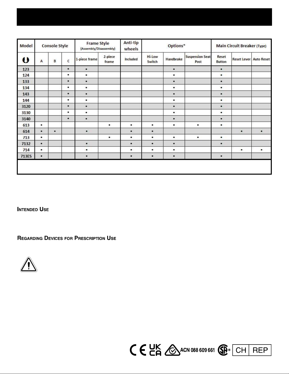
(Optional) Handbrake: This lever provides you with supplemental stopping power. See II. “Your Scooter.”
HANDBRAKE LEVER (IF EQUIPPED)
The handbrake lever contains hydraulic fluid. When the lever is depressed, the fluid is pushed through the brake
line to engage the brake pads against the brake discs. The handbrake lever is a completely sealed unit, meaning
that the hydraulic fluid should not leak; however, there are certain safety measures that should be taken if the
handbrake lever becomes cracked or damaged.
Do not touch spilled material unless wearing protective equipment, such as safety goggles and gloves.
For small spills, cover the material with dry earth, sand or other non-combustible absorbent material. Once
absorbed, enclose the material in a plastic bag and contact your local waste disposal agency for proper disposal
measures. Do not expose the material to waterways or sewers.
If the eyes are exposed, check for and remove contact lenses. Flush eyes with cool, clean, low-pressure water
while occasionally lifting and lowering the eyelids. Seek medical attention if excessive tearing, redness or
pain persists.
If the skin is exposed, remove all contaminated clothing. Wipe offexcess material and wash exposed skin
with soap and water. Seek medical attention if skin appears damaged or if irritation persists. Thoroughly clean
contaminated clothing before reuse. Discard contaminated leather goods.
If ingested, do not induce vomiting or give anything to drink unless directed to by a physician. Never give
anything by mouth to a person who is not fully conscious. Seek medical attention immediately.
If inhaled, move the affected individual to fresh air. If the affected individual is not breathing, immediately
begin rescue breathing. If breathing is difficult, 100% humidified oxygen should be administered by a qualified
individual. Seek medical attention immediately and keep the affected individual warm and at rest.
If ignited, use dry chemical, foam, carbon dioxide or water fog to extinguish.
WARNING! Do not modify the handbrake lever or attempt to replace the hydraulic fluid. If damage
occurs, follow the safety information in this section and contact your authorized provider for
handbrake replacement. The hydraulic handbrake should only be serviced or replaced by your
authorized provider.
WARNING! The handbrake contains hydraulic fluid that can cause mild skin, eye and nasal/
bronchial irritation. Do not attempt to adjust or service the handbrake without proper protective
equipment such as safety goggles and gloves, and wash hands after handling.

Full-size Scooter Series 7
EN
II. YOUR SCOOTER
TILLER CONSOLE
The tiller console houses all of the controls needed to drive your scooter, including the speed adjustment dial, key
switch, battery condition meter, status LED, horn buttons, turn signal buttons, handbrake lever, tiller adjustment
lever, and the throttle control lever. Please note that some of the features listed in this section are optional items
and may not appear on your scooter. See figure 1.
NOTE: If your scooter is equipped with an LCD Control Panel, please advance to the page in this section that
begins TILLER CONSOLE: LCD CONTROL PANEL.
NOTE: If your scooter is equipped with an optional handbrake, please advance to the page in this section that
begins TILLER CONSOLE: HANDBRAKE LEVER.
PROHIBITED! Do not expose the tiller console to moisture. In the event that the tiller console
does become exposed to moisture, do not attempt to operate your scooter until the tiller console
has dried thoroughly.
IDENTIFICATION KEY
1. HORN BUTTON
2. *LEFT TURN SIGNAL BUTTON
3. *HAZARD LIGHTS SWITCH
4. LIGHT SWITCH
5. *RIGHT TURN SIGNAL BUTTON
6. *HI-LOW SWITCH
7. THROTTLE CONTROL LEVER
8. SPEED ADJUSTMENT DIAL
9. BATTERY CONDITION METER
10. KEY SWITCH
11. MIRROR AND MIRROR PLUGS
12. *TILLER ADJUSTMENT LEVER
13. *HANDBRAKE LEVER
14. *BRAKE LOCK
11
8 9 10
13
12
11
7
1
2 5
11
6
4
3
14
7
Figure 1.Tiller Console Components - Style A
*OPTIONAL COMPONENTS AVAILABLE ON SOME MODELS
**LOCATION OF HI-LOW SWITCH MAY VARY DEPENDING ON MODEL**

8 Full-size Scooter Series
EN
II. YOUR SCOOTER
Horn Buttons
These buttons activate a warning horn. Your scooter must be powered up for the horn to be operational. Do not
hesitate to use the warning horn when doing so may prevent accident or injury.
Turn Signal Buttons
Use these buttons to turn on the left and right turn signal (amber) lights.
Push the left button to activate the left turn signal light. The turn signal LED located in the battery condition
meter will flash.
Push the right button to activate the right turn signal light. The turn signal LED located in the battery condition
meter will flash.
The turn signals are timed to shut offautomatically.
Lights Switch
This switch controls your scooter’s lighting system.
Toggle the switch forward to turn on the lighting system.
Toggle the switch rearward to turn offthe lighting system.
WARNING! Scooter users are required to use their lights when visibility is restricted—day or night.
Hazard Lights Switch
This switch activates the 4-way flashers on your scooter.
Toggle the hazard lights switch forward to turn on the flashers.
Toggle the hazard lights switch rearward to turn offthe flashers.
Hi-Low Switch
This switch toggles the scooter’s speed between Hi and Low. Toggle the switch forward (Hi) to achieve the
maximum preprogrammed speed for the scooter. Toggle the switch rearward (Low) to achieve half the maximum
preprogrammed speed of the scooter.
Throttle Control Lever
This lever allows you to control the forward speed and the reverse speed of your scooter up to the maximum speed
you preset with the speed adjustment dial.
NOTE: The throttle control lever operation instructions outlined below apply to scooters in a standard
configuration. If the programming of your scooter was modified in any way by an authorized provider, contact
that provider for correct throttle control level operation instructions.
To Move Forward, use either of the following:
Use your left thumb to push the left side of the throttle control lever.
Use your right hand fingers to pull back on the right side of the throttle control lever.
To Move Rearward, use either of the following:
Use your right thumb to push the right side of the throttle control lever.
Use your left hand fingers to pull back on the left side of the throttle control lever.
Release the throttle control lever and allow your scooter to come to a complete stop before engaging the other side
of the lever. When the throttle control lever is completely released, it automatically returns to the center “stop”
position and engages your scooter’s brakes.
Speed Adjustment Dial
This dial allows you to preselect and limit your scooter’s top speed.
The image of the tortoise represents the slowest speed setting
The image of the hare represents the fastest speed setting.

Full-size Scooter Series 9
EN
II. YOUR SCOOTER
Battery Condition Meter
When the key is fully inserted and turned clockwise to power up your scooter, this meter indicates the approximate
battery voltage strength. For further information on battery charging, see III. “Batteries and Charging.”
Status LED
The status LED alerts you to electrical problems that may occur with the scooter. The LED remains constantly lit
while your scooter is on. If your scooter develops an electrical problem, the status LED will flash a code. See VII.
“Basic Troubleshooting” for flash codes.
Key Switch
Insert the key into the key switch and turn it clockwise to power up (turn on) your scooter.
Turn the key counterclockwise to power down (turn off) your scooter.
WARNING! When faced with an emergency situation, switch off the key to power off the scooter.
Use caution. Be advised that turning off power to the scooter may cause the scooter to stop
abruptly. To release the emergency stop and restore driving capability to the scooter, release
the throttle control lever and then switch on the key to the scooter.
WARNING! If the key is turned to the “off” position while your scooter is in motion, the electronic
brakes will engage and your scooter will come to an abrupt stop.
Mirror Positioning and Adjustment
For information on positioning and adjusting your mirror, see V. “Comfort Adjustments.”
Tiller Angle Adjustment
For information on positioning and adjusting your tiller, see V. “Comfort Adjustments.”
Handbrake Lever
This lever provides you with supplemental stopping power. When in
motion, release the throttle control lever and gently squeeze the handbrake
lever to come to a stop. Handbrake effectiveness can be modified by
tightening or loosening the setscrew located on the handbrake lever.
WARNING! The handbrake is intended for use as a
supplemental braking.
Off-board Charger Port
The off-board charger power cord plugs into this port during battery
charging. The off-board charger port is located on the tiller. See figure 2.
Electrical System Fuses
Your scooter is equipped with a series of electrical system fuses, which
help protect the off-board charging system, key switch and lighting system
from receiving an overload of electrical current. These fuses are the same
type used in automobiles and are located in a compartment on the tiller.
See figure 2. See VIII. “Care and Maintenance” for fuse replacement.
NOTE: Keep all electrical areas clean and free of moisture and
foreign material.
IDENTIFICATION KEY
1. OFF-BOARD CHARGER PORT
2. OFF-BOARD CHARGER FUSE
3. KEY SWITCH FUSE
4. LOWER HEADLIGHT FUSE
5. REAR TAIL LIGHTS FUSE
6. LEFT TURN SIGNAL FUSE
7. RIGHT TURN SIGNAL FUSE
1
2
4
6
7
5
3
Figure 2. Off-board Charger Port/Tiller
Console Fuses

10 Full-size Scooter Series
EN
Tiller Console: Handbrake Lever
Your scooter is equipped with a handbrake lever which is located on the tiller handle. See figure 1 and figure 7.
This lever provides you with additional stopping power. The handbrake is manual and operates independently
of your scooter’s regenerative braking system which is engaged during operation of the scooter by releasing the
throttle control lever.
Figure 3. Handbrake Lever
IDENTIFICATION KEY
1. HANDBRAKE LEVER
2. SETSCREW
1
2
To operate the handbrake lever:
1. Release the throttle control lever fully.
2. Gently squeeze the handbrake lever to bring your
scooter to a complete stop.
NOTE: You must release the throttle control lever before
squeezing the handbrake lever. Otherwise, your scooter
may not come to a complete stop.
NOTE: The handbrake lever may require periodic
adjustment to maintain proper operation. Adjustment
should only be performed by your authorized provider
or other qualified technician. Contact your authorized
provider for more information.
NOTE: Handbrake effectiveness, which is how quickly the squeezing of the handbrake lever will bring your
scooter to a stop, can be modified by tightening or loosening the setscrew located on the handbrake lever. See
figure 3.
NOTE: If your handbrake is equipped with a lock function as shown in figure 1 or figure 7, you can activate
the brake lock function by squeezing the handbrake lever and rotating or pushing the lock lever to engage the
lock. To release the handbrake lock, fully squeeze the handbrake lever. See figure 1 or figure 7.
NOTE: If your handbrake contains hydraulic fluid, do not attempt to modify or replace the handbrake lever
or the hydraulic fluid.
NOTE: Prior to riding your scooter, especially after storage, squeeze the handbrake lever fully five to seven
(5-7) times to confirm proper function of the handbrake.
WARNING! The hydraulic fluid can cause mild skin, eye, and nasal/bronchial irritation. If damage
occurs, contact your authorized provider for handbrake replacement. The hydraulic
handbrake should only be serviced or replaced by your authorized provider.
WARNING! The handbrake is intended for use as a supplemental braking system to the throttle
controlled regenerative braking system, or to help bring the scooter to a stop in the event that
the regenerative braking system does not engage. The handbrake is not intended for use as the
primary braking system. Misuse or improper use of the handbrake may result in a crash, a fall,
personal/property injury, or death.
II. YOUR SCOOTER

Full-size Scooter Series 11
EN
TILLER CONSOLE: LCD CONTROL PANEL
The tiller console and lower tiller house all of the controls needed to drive your scooter, including the LCD control
panel, throttle control levers, key switch, and the throttle control lever switch. See figure 4.
PROHIBITED! Do not expose the tiller console to moisture. In the event that the tiller console
does become exposed to moisture, do not attempt to operate your scooter until the tiller console
has dried thoroughly.
NOTE: Not all options are available on all styles of consoles with LCD displays.
Horn Buttons
These buttons activate a warning horn. Your scooter
must be powered up for the horn to be operational. Do
not hesitate to use the warning horn when doing so
may prevent accident or injury.
Turn Signal Buttons
Press the appropriate turn signal button once to
activate it. The turn signal will flash on the LCD
screen.
Press the same signal button to turn it off.
NOTE: The turn signals are timed to shut offafter
15 seconds. A warning beep will sound as long as the
turn signal is on. See figure 5 for volume control.
Lights Button
Press the lights button once to activate the lighting
system. The light symbol will be shown on the
LCD screen.
Press the lights button again to turn the lighting
system off.
WARNING! Scooter users are required
to use their lights when visibility is
restricted—day or night.
LCD Screen and Control Panel Settings
The LCD control panel offers easily intuited feedback
information via the LCD screen. See figure 4. The
LCD screen is also used during the set-up (activation)
of the various control panel settings.
II. YOUR SCOOTER
IDENTIFICATION KEY
1. HORN BUTTON
2. TURN SIGNAL BUTTONS
3. LIGHTS BUTTON
4. LCD SCREEN
5. SET BUTTON
6. HAZARD LIGHTS BUTTON
7. MODE BUTTON
8. HI-LOW BUTTON
9. SPEED ADJUSTMENT
(INCREASE)
10. SPEED ADJUSTMENT
(DECREASE)
11. THROTTLE CONTROL
10
9
8
2
3
1
1
2
7
6
5
4
11
Figure 4. LCD Control Panel - Style B

12 Full-size Scooter Series
EN
Hazard Lights Button
This button activates the 4-way yellow flashers on your scooter.
Press the button once to turn on the flashers.
Press the button again to turn offthe flashers.
NOTE: The 4-way flashers will flash and a warning beep will sound as long as the hazard lights are on. See
figure 6 for volume control.
Mode Button
Use the mode button to scroll between the odometer, tripometer, temperature, and clock (Style B) and odometer,
tripometer, clock and brightness display (Style C).
High-Low Button
This button toggles the scooter’s speed between HIGH and LOW.
Press the High-Low button once to set the speed adjustment to High. The High-Low indicator will display on
the LCD screen. See figure 5. Using this setting in conjunction with the speed adjustment buttons will allow
the scooter to achieve speeds up to the maximum preprogrammed speed for the scooter.
Press the High-Low button again to set the speed adjustment to Low. The High-Low indicator will not display
on the LCD screen. Using this setting in conjunction with the speed adjustment buttons will allow the scooter
to achieve speeds up to the half the maximum preprogrammed speed for the scooter.
Speed Adjustment Buttons
These adjustment buttons enable you to pre-select and limit your scooter’s speed.This is indicated by the maximum
speed indicator on the LCD screen. See figure 5.
Press the image of the tortoise to decrease the speed of the scooter.
Press the image of the hare to increase the speed of the scooter.
NOTE: The more bars shown on the maximum speed indicator, the faster your pre-selected maximum speed
will be. See figure 5.
Throttle Control Levers
These levers allow you to control the forward speed and the reverse speed of your scooter up to the maximum
speed you preset with the speed adjustment buttons. A throttle control lever is located on the underside of the left
and right side of the tiller handle. See Figure 4.
To Move Forward:
Squeeze the rear part of the throttle control lever.
To Move Rearward:
Squeeze the front part of the throttle control lever.
Release the throttle control lever and allow your scooter to come to a complete stop before engaging the other side
of the lever. When the throttle control lever is completely released, it automatically returns to the center “stop”
position and engages your scooter’s brakes.
II. YOUR SCOOTER

Full-size Scooter Series 13
EN
II. YOUR SCOOTER
LCD SCREEN AND CONTROL PANEL SETTINGS
The LCD control panel offers easily intuited feedback information via the LCD screen. See figure 5. The LCD
screen may also be used during the set-up (activation) of the various control panel settings. See chart 1.
IDENTIFICATION KEY
1. BATTERY CONDITION INDICATOR
2. LIGHTS INDICATOR
3. SPEED/ERROR CODE/VOLUME
4. HI-LOW INDICATOR
5. UNIT INDICATOR
6. MAXIMUM SPEED INDICATOR
7. RIGHT TURN INDICATOR
8. AM/PM
9. CLOCK
10. TEMPERATURE
11. DISTANCE/TIME/TEMP/ERROR MESSAGE
12. TRIPOMETER
13. ODOMETER
14. BRIGHTNESS
15. LEFT TURN INDICATOR
16. FAULT CODE INDICATOR*
13
15 7
1012
11
98
6
5
4
3
2
1
B
Figure 5. LCD Screen - Console Style B (Top) and Console Style C (Bottom)
*FOR FAULT CODE INDICATOR INFORMATION SEE FIGURE 27
1
9 8
2
7
15
16
10
3
1213
5
C
14

14 Full-size Scooter Series
EN
SETTING INFORMATION CHART
SETTING CODE INFORMATION
Odometer ODO Measures mph, km/h, and hours of use. Also displays total distance traveled
over life of scooter. (Cannot be reset.)
Tripometer TRIP Displays trip distance traveled. Can be reset to “0”.
Temperature TEMP Displays current temperature in °F or °C.
Clock Displays time in 12-hour (AM/PM) or 24-hour.
Brightness (style C Only) 000 Allows user to alternate between levels of brighness for LCD Screen.
SETTING ODO TRIP TEMP
OPERATION Press the MODE button
until ODO option
appears.
Press the MODE button
until TRIP option
appears.
Press the MODE button
until TEMP option
appears.
Press and hold MODE button
until the clock symbol appears
on screen.
SELECTION
Press and hold SET,
then simultaneously
press the MODE button
until the setting option
flashes. Scroll through
the options by pressing
the SET button.
Press and hold SET, then
simultaneously press
the MODE button for
2 seconds and release.
Press and hold SET until
Tripometer resets to 0.0.
Press and hold SET,
then simultaneously
press the MODE
button until the setting
option flashes. Scroll
through the options (°F
or °C) by pressing SET
button.
Press and hold SET, then
simultaneously press the
MODE button until the hour
digit flashes. Use the SET
button to increase the hour to
the correct number. Continue
to use the MODE and SET
buttons to program the minutes
and AM/PM setting.
EXIT When desired option
flashes, press any button
except SET to exit.
Press any button except
SET to exit.
When your choice is
flashing, press any
button except SET to
exit.
Press any button except
MODE or SET to exit.
II. YOUR SCOOTER
Chart 1. LCD Control Panel Information
Chart 2. LCD Control Panel Information - Style B
Press MODE until the setting you want to change appears on the LCD screen. Press and hold SET then follow
the steps corresponding to your setting in chart 2.

Full-size Scooter Series 15
EN
II. YOUR SCOOTER
Battery Charging Mode
During battery charging, the console will display the clock and the battery condition indicator.
Battery Condition Indicator
When the key is turned to the “on” position, this indicator gives an approximate reading of battery strength. When the
scooter’s battery voltage reaches a low enough level, a warning beep will sound once, indicating the batteries need
charging. The warning beep will not sound again until the scooter is restarted or the throttle control lever is pressed.
Mode Button
Use the mode button to scroll between the odometer, tripometer, temperature, and clock (Style B) and odometer,
tripometer, clock and brightness display (Style C). See Figure 7. Through a series of presses and holds, you can
change the settings on your console. See Chart 3 for more information.
SETTING TRIP BRIGHTNESS UNIT OF MEASURE
OPERATION Press the MODE
button until TRIP
option appears.
Press the MODE button
until 000 option appears.
Press and hold the MODE
button until ODO option
appears.
Press MODE button until the ODO
symbol appears on screen.
SELECTION
Press and hold
MODE until
Tripometer resets
to 0.0.
Press and hold the
MODE button until 000
flashes. Press MODE
to toggle between
LCD Screen brightness
settings (100%, 75%,
50%) until desired
brightness is reached.
Press and hold until Distance/
Temperature flashes. Scroll
through the options (°F or
°C/Miles or Kilometers) by
pressing MODE button.
Press and hold the MODE button once
(1) for unit of measure. Press and Hold
MODE twice (2) to switch between
AM/PM by pressing MODE button.
Press and hold the MODE button a
third (3) time to set the hour by pressing
the MODE button before pressing and
holding the MODE button a fourth (4)
time to adjust and set the minute by
pressing the MODE button.
EXIT N/A Press and hold MODE
button to exit.
Press and hold the MODE
button to move to Time Settings.
Press and hold the MODE button to
exit.
Chart 3. LCD Control Panel Information - Style C
Chart 4. LCD Control Panel Information - Style C - Flowchart
Distance/
Temp Imperial Metric Time
Adjust Hour Minute EXIT
ODO Trip 000 AM/PM Hour
Adjust
Minute
Adjust
EXIT
Reset
Trip
Brightness
100%
Brightness
75%
Brightness
50%
Press and Hold
Press

16 Full-size Scooter Series
EN
II. YOUR SCOOTER
Maximum Speed Indicator
The maximum speed indicator displays the maximum
speed selected with the speed adjustment buttons. The
more bars that are lit, the faster the speed. The maximum
scooter speed will be determined by the HIGH-LOW
setting, which limits the maximum speed to half when
set to LOW. The actual travel speed will be shown in the
speed display on the LCD screen.
Volume Control
Turn signals, hazard lights, low voltage, and error
messages can be set to both blink and beep. The horn is
relay operated and its volume cannot be adjusted. See
figure 6.
To set the volume:
1. Ensure the key is in the “off” position.
2. Press the appropriate two buttons simultaneously
(see chart 5), and turn the key to the “on” position.
3. Once the volume control screen appears, release the
buttons.
4. Press the hare button to increase the volume to a value
of 4 and the tortoise button to decrease the volume
of the beep to 0 (0 indicates offand 4 indicates the
loudest volume).
5. To exit, press any button except the hare or tortoise.
NOTE: The error message language option is set the
same way as the volume.
IDENTIFICATION KEY
1. VOLUME/LANGUAGE OPTION
2. FUNCTION INDICATOR
1
2
Figure 6. Volume Control Display
Chart 5. Volume Control Information
FUNCTION BUTTONS FUNCTION INDICATOR
Hazard Lights SET + HAZARD LIGHTS SET 1
Low Voltage SET + LEFT TURN INDICATOR SET 3
Turn Signals SET + RIGHT TURN INDICATOR SET 4
Error Message
Language
Option
SET + LIGHTS SET 5
6- Spanish
5- Italian
4- French
3- German
2- Dutch
1- English
0- Close

Full-size Scooter Series 17
EN
II. YOUR SCOOTER
IDENTIFICATION KEY
1. HAND BRAKE LEVER
2. HORN BUTTON
3. RIGHT TURN SIGNAL BUTTON
4. HEADLIGHT SWITCH
5. LCD SCREEN**
6. SPEED ADJUSTMENT DIAL
7. HAZARD SWITCH
8. LEFT TURN SIGNAL BUTTON
9. HORN BUTTON
10. LEFT TURN SIGNAL BUTTON
11. THROTTLE CONTROL LEVER
12. THROTTLE CONTROL LEVER
13. RIGHT TURN SIGNAL BUTTON
14. MODE BUTTON
15. *THROTTLE CONTROL PADDLE
Figure 7.Tiller Console Components - Style C
*OPTIONAL COMPONENTS AVAILABLE ON SOME MODELS
**FOR LCD SCREEN INFORMATION SEE FIGURE 5.
1
2
11
10 13
12
4 7
35
689
15
14
Horn Buttons
These buttons activate a warning horn. Your scooter must be powered up for the horn to be operational. Do not
hesitate to use the warning horn when doing so may prevent accident or injury.
Turn Signal Buttons
Use these buttons to turn on the left and right turn signal (amber) lights.
Push the left button to activate the left turn signal light. The turn signal indicator located in the LCD screen
will flash.
Push the right button to activate the right turn signal light. The turn signal indicator located in the LCD screen
will flash.
The turn signals are timed to shut offautomatically.

18 Full-size Scooter Series
EN
Lights Switch
This switch controls your scooter’s lighting system.
Toggle the switch to the right to turn on the lighting system.
Toggle the switch to the left to turn offthe lighting system.
WARNING! Scooter users are required to use their lights when visibility is restricted—day or night.
Hazard Lights Switch
This switch activates the 4-way flashers on your scooter.
Toggle the hazard lights switch to the right to turn on the flashers.
Toggle the hazard lights switch to the left to turn offthe flashers.
Speed Adjustment Dial
This dial allows you to preselect and limit your scooter’s top speed.
The image of the tortoise represents the slowest speed setting
The image of the hare represents the fastest speed setting.
Power Button (Optional – For use with NFC Card Reader)
The power button allows you to turn your scooter on and off.
Press the power button to turn your scooter on and to use the NFC card reader. Once fully engaged and
latched, the power button will emit a blue light. The power button is used in conjunction with the NFC card
reader for additional security for your scooter. See “NFC Card Reader” for more information.
Press the power button again to power down (turn off) your scooter.
WARNING! When faced with an emergency situation, switch off the key to power off the scooter.
Use caution. Be advised that turning off power to the scooter may cause the scooter to stop
abruptly. To release the emergency stop and restore driving capability to the scooter, release
the throttle control lever and then switch on the key to the scooter.
WARNING! If power button is pushed while your scooter is in motion, the electronic brakes will
engage and your scooter will come to an abrupt stop.
NFC Card Reader (Optional)
The Near Field Communication (NFC) card reader provides additional security for your scooter as no 2 keys
are the same. The NFC card reader enables you to turn on your scooter with the added security of Near Field
Communication (NFC).
To use the NFC card reader:
1. Press the power button on the scooter until it is fully engaged and latched.
2. Hold the NFC card over the card reader.
3. A 4-note audible sound will indicate successful pairing of the NFC card and your scooter.
4. They key may now be placed in a safe place while operating your scooter.
5. The scooter may now be driven.
NOTE: Once the power button is fully engaged and latched, you will have ten (10) seconds to pair the NFC
card with your scooter. If you are unable to pair your scooter, press the power button to turn offyour scooter,
wait ten (10) seconds, and then press the power button to turn your scooter back on to try again.
6. To power down (turn off) your scooter, press the power button again.
II. YOUR SCOOTER

Full-size Scooter Series 19
EN
II. YOUR SCOOTER
Throttle Control Lever
This lever allows you to control the forward speed and the reverse speed of your scooter up to the maximum speed
you preset with the speed adjustment dial.
NOTE: The throttle control lever operation instructions outlined below apply to scooters in a standard
configuration. If the programming of your scooter was modified in any way by an authorized provider, contact
that provider for correct throttle control level operation instructions.
To Move Forward, use either of the following:
Use your left thumb to push the left side of the throttle control lever.
Use your right hand fingers to pull back on the right side of the throttle control lever.
To Move Rearward, use either of the following:
Use your right thumb to push the right side of the throttle control lever.
Use your left hand fingers to pull back on the left side of the throttle control lever.
Release the throttle control lever and allow your scooter to come to a complete stop before engaging the other side
of the lever. When the throttle control lever is completely released, it automatically returns to the center “stop”
position and engages your scooter’s brakes.
If not equipped with toggles, use the following directions for throttle control paddles:
These paddles allow you to control the forward speed and the reverse speed of your scooter up to the maximum
speed you preset with the speed adjustment buttons. A throttle control paddle is located on the underside of the
left and right side of the tiller handle. See Figure 7.
To Move Forward:
Squeeze the rear part of the throttle control paddle.
To Move Rearward:
Squeeze the front part of the throttle control paddle.
Release the throttle control paddle and allow your scooter to come to a complete stop before engaging the other
side of the paddle. When the throttle control paddle is completely released, it automatically returns to the center
“stop” position and engages your scooter’s brakes.
Handbrake Lever
This lever provides you with supplemental stopping power. When in motion, release the throttle control lever and
gently squeeze the handbrake lever to come to a stop. Handbrake effectiveness can be modified by tightening or
loosening the setscrew located on the handbrake lever.
WARNING! The handbrake is intended for use as a supplemental braking.

20 Full-size Scooter Series
EN
43
5
1
8
2
7
B
II. YOUR SCOOTER
LOWER TILLER (available on models 123, 124, 133,
134, 143, 144, 614, 714, 3120, 3130 and 3140 only)
Off-board Charger Port
The off-board charger power cord plugs into this port
during battery charging. The off-board charger port will be
located on the tiller. See figure 8.
Electrical System Fuses
For information and a complete description of the fuse
system, see figure 2.
Tiller Adjustment Lever orTiller Adjustment Knob
See V. “Comfort Adjustments”.
Key Switch
Insert the key into the key switch and turn it clockwise
to power up (turn on) your scooter. See figure 8.
Turn the key counterclockwise to power down (turn
off) your scooter.
WARNING! When faced with an emergency
situation, switch off the key to power off
the scooter. Use caution. Be advised that
turning off power to the scooter may cause
the scooter to stop abruptly. To release
the emergency stop and restore driving
capability to the scooter, release the
throttle control lever and then switch on
the key to the scooter.
WARNING! If the key is turned to the “off”
position while your scooter is in motion,
the electronic brakes will engage and your
scooter will come to an abrupt stop!
Throttle Control Lever Switch
This switch dictates which throttle control lever (left or
right) will function. See figure 8.
Toggle the switch up to activate the left throttle control
lever.
Toggle the switch down to activate the right throttle
control lever.
IDENTIFICATION KEY
1. OFF-BOARD CHARGER PORT
2. FUSE PANEL
3. TILLER ADJUSTMENT KNOB
4. KEY SWITCH
5. *THROTTLE CONTROL LEVER SWITCH
6. WATER BOTTLE HOLDER
7. MIRROR
8. USB CHARGER
Figure 8. Lower Tiller Components
6
2
1
3 5 4
7
A
*OPTIONAL COMPONENTS AVAILABLE ON SOME
MODELS
*MODELS 614 OR 714
This manual suits for next models
15
Table of contents
Languages: