PVA DeltaTherm User manual

DeltaTherm IR Cure Module
Operation Manual
Revision B
WHERE
PRECISION
DRIVES
PRODUCTION

DeltaTherm IR Cure Module
Revision B /February 2020 Page 2 of 41
This document is based on information available at the time of its publication. While efforts
have been made to ensure the contents of this manual are accurate, the information
contained herein does not purport to cover all specific details or variations in hardware, or
to provide for every possible contingency in connection with installation, operation, or
maintenance. Features may be described herein which are not present in all hardware and
software systems. Precision Valve and Automation, Inc. assumes no obligation of notice to
holders of this document with respect to changes subsequently made.
Precision Valve and Automation, Inc. makes no representation or warranty, expressed,
implied, or statutory with respect to, and assumes no responsibility for the accuracy,
completeness, sufficiency, or usefulness of the information contained herein. No warranties
of merchantability or fitness for purpose shall apply.
This document, including the information contained herein, is the property of
Precision Valve and Automation, Inc. and is considered confidential and proprietary
information. It is delivered on the express condition that it not be used, disclosed, or
reproduced, in whole or in part, for any reason without prior written consent of
Precision Valve and Automation, Inc.
Copyright © 2020
Precision Valve and Automation, Inc.
All Rights Reserved.

DeltaTherm IR Cure Module
Revision B /February 2020 Page 3 of 41
Table of Contents
Introduction...........................................................................................................5
PVA Contact Information........................................................................................................5
Document History.....................................................................................................................5
Safety ..........................................................................................................................................6
Theory of Operation ................................................................................................................ 8
Personal Protective Equipment............................................................................................ 8
Waste Disposal.......................................................................................................................... 8
Hazards Due to Contact ......................................................................................................... 8
Operating, Handling, Transportation, and Storage ......................................... 9
Dust and Debris.........................................................................................................................9
Temperature and Humidity.....................................................................................................9
Location ......................................................................................................................................9
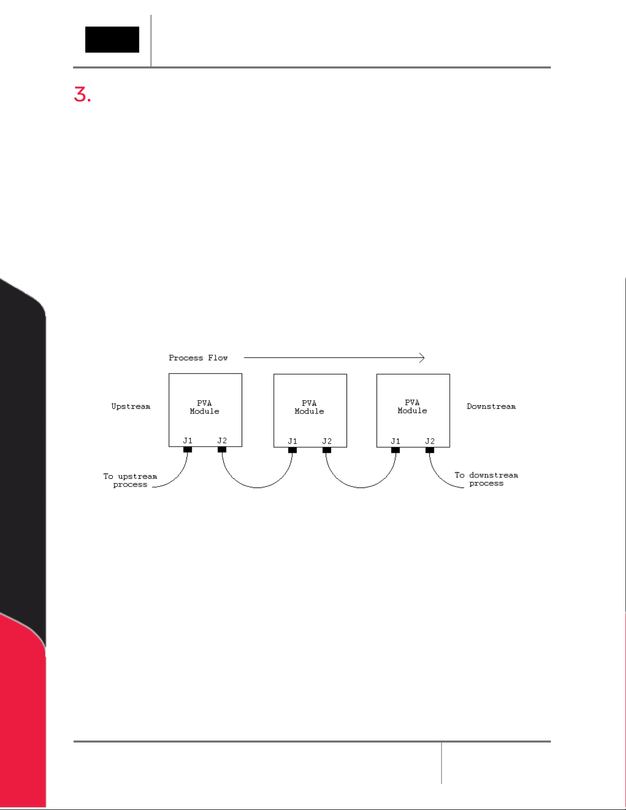
SMEMA .................................................................................................................. 10
Installation and Setup .........................................................................................11
Installation.................................................................................................................................11
Operating Safety ................................................................................................. 12
Notices and Warnings ............................................................................................................12
Safety Devices and Guarding...............................................................................................12
Safety Circuit ................................................................................................................... 12
Doors..................................................................................................................................12
Exhaust Requirements ..........................................................................................................13
Air Velocity Test Point....................................................................................................13
Operation.............................................................................................................. 14
Startup Procedure ..................................................................................................................14
Light Tower Operation ...........................................................................................................15
Machine Safety Check ...........................................................................................................16
Shutdown Procedure.............................................................................................................16
Cycle Stop................................................................................................................................. 17
Auto Cycle ............................................................................................................ 18

DeltaTherm IR Cure Module
Revision B /February 2020 Page 4 of 41
Manual Mode ....................................................................................................... 20
IR Panels .................................................................................................................................. 20
Conveyor Speed ......................................................................................................................21
Conveyor Width .......................................................................................................................21
Conveyor Jog.......................................................................................................................... 22
Sensors .................................................................................................................................... 23
SMEMA Control....................................................................................................................... 23
Setup Mode.......................................................................................................... 24
IR Panels .................................................................................................................................. 24
Conveyor Speed..................................................................................................................... 26
Conveyor Width .......................................................................................................................27
Rename Recipe....................................................................................................................... 28
Global Settings ....................................................................................................................... 29
Fault Recovery Procedure ................................................................................ 30
Recovery from Emergency Stop or Open Door Error..................................................... 30
Recovery from an Exhaust or Intake Fan Failure............................................................ 30
Recovery from a Parameter Out of Range Error............................................................. 30
Recovery from an Over-Temperature Error......................................................................31
Recovery from an Auto Conveyor Adjust Error................................................................31
Error Messages ....................................................................................................32
Troubleshooting..................................................................................................35
Calling Technical Support .................................................................................................... 35
Fault Diagnosis....................................................................................................................... 36
Maintenance ........................................................................................................37
Notes .................................................................................................................... 38
Warranty ...............................................................................................................39
PVA Warranty Policy.............................................................................................................. 39
Appendix A – Definitions ................................................................................... 40
Table of Figures ................................................................................................... 41

DeltaTherm IR Cure Module
Revision B /February 2020 Page 5 of 41
Introduction
Before you operate this system, read the operation and setup manual. This will help you to
become familiar with the product and ensure successful operation.
If any questions or problems arise, contact PVA’s Technical Support department.
PVA Contact Information
Main Office
Technical Support
PVA
Six Corporate Drive
Halfmoon,NY 12065
Tel +1-518-371-2684
Fax +1-518-371-2688
Website: https://pva.net
Email: [email protected]
Tel +1-844-734-0209
Email: [email protected]
Document History
Revision
Revision Date
Reason for Changes
REV B
January 2020
DeltaTherm Version 1.9 Release
REV A
December 2018
Initial Release
Note: All photographs and CAD model representations in this document are a
“general representation” of the system and its components. The actual appearance
of the system and its components can differ based upon customer specific
configuration.

DeltaTherm IR Cure Module
Revision B /February 2020 Page 6 of 41
Safety
Certain warning symbols are affixed to the machine and correspond to notations in this
manual. Before operating the system, identify these warning labels and read the notices
described below. Not all labels may be used on any specific system.
Always wear approved safety glasses when you operate or work near the
workcell.
Before you operate the system, read and understand the manuals provided
with the unit.
Never put hands or tools in areas with this symbol when the machine is in
operation. A dangerous condition may exist.
Read and understand the manuals provided with the unit before any repairs
or maintenance is done. Only a qualified individual should do service.
Use caution when there are pressurized vessels. Find and repair any leaks
immediately. Always wea
r appropriate safety equipment when you work
with pressurized vessels or vessels that contain chemicals
Shear hazard from moving parts. Avoid contact.
Do not remove protective guarding.
In situations where inattention could cause either personal injury or damage
to equipment, a warning notice is used.

DeltaTherm IR Cure Module
Revision B /February 2020 Page 7 of 41
Do not smoke near the PVA UV cure machine. Always have a fire
extinguisher available for emergency use.
Before performing any repairs or maintenance to the system, turn off power
and lock out the power disconnect switch.
Warning notices are used to emphasize that hazardous voltages, current,
temperatures, or other conditions that could cause personal injury exist in
this equipment or may be associated with its use. Only qualified personnel
should enter areas designated with this symbol.
Laser light source present. Do not stare directly into the beam. Do not use in
the presence of highly reflective surfaces
Pinch hazard from moving parts. Avoid contact.
Hot surface. Avoid contact.
Warning, Ultraviolet (UV) light hazard. Do not look directly at the UV light
source.

DeltaTherm IR Cure Module
Revision B /February 2020 Page 8 of 41
Theory of Operation
The DeltaTherm IR Cure Module is an infra-red (IR) curing machine that can handle multiple
boards. Upstream and downstream ends are SMEMA (Surface Mount Equipment
Manufacturers Association) rated for use in a production line. The system is designed to
operate with PVA workcells.
The operator controls the machine with the operator interface; this includes setup, manual
operation, and automatic operation. Machine status and error messages are shown on the
screen and the light tower. The operator(s) must, by reading the manual or by training,
understand the operation of this machine. Any uses other than those listed above could
result in a dangerous condition and cannot be protected against by the safety features
installed on the system.
Figure 1: DeltaTherm IR Cure Module Functional Block Diagram
Personal Protective Equipment
Operators must use eye protection. Always wear gloves when handling materials and
solvents. Refer to MSDS sheets on the material being dispensed for other precautions.
Waste Disposal
Dispose of all used parts and materials in accordance with local laws and regulations.
Hazards Due to Contact
The DeltaTherm IR Cure Module is made to minimize injury from contact with any
accessible portion of the machine. In some modes, it is possible to access the work area
while the machine operates. Only a qualified person should do this. All hot surfaces have a
warning label.

DeltaTherm IR Cure Module
Revision B /February 2020 Page 9 of 41
Operating, Handling, Transportation, and
Storage
The system should have minimal vibration when handled and transported. Use an air-ride
truck for roadway transport. The machine is made to operate in an industrial environment
but abuse will reduce its performance.
Dust and Debris
All enclosures and connector covers should be closed tightly. Put a cover over the system
if dust or other airborne debris is present in the storage area.
Temperature and Humidity
Storage and operation should be done in an area at 40-105°F (4– 41°C) and low humidity.
Do not let the machine have condensation on it.
Location
The machine should be installed and stored on a level surface away from standing water,
possible overspray, and leaks.

DeltaTherm IR Cure Module
Revision B /February 2020 Page 10 of 41
SMEMA
For manufacturing lines (multiple machines utilizing conveyor systems), it is necessary for
the individual modules to communicate reliably. Make sure the SMEMA and Intermodule
cables are correctly connected.
Note: On the diagrams, the J# refers to the label on the machine, not the label on the
cable.
The Surface Mount Equipment Manufacturers Association (SMEMA) Electrical Equipment
Interface Standard is used to make sure the sequence of boards is correct. If these
connections are not in place, boards cannot move from one machine to another.
SMEMA cables have male 14-pin amp-type CPC connectors. The cables are straight-
through so orientation does not matter. On each module, the wire to the J1 plug must
connect to the J2 plug on the machine upstream. Similarly, the J2 plug on each machine
must connect to the J1 plug on the machine downstream, as shown below.
Figure 2: SMEMA Process Flow

DeltaTherm IR Cure Module
Revision B /February 2020 Page 11 of 41
Installation and Setup
WARNING: The following procedures should be done by qualified persons in
accordance with this manual and applicable safety regulations. A “qualified person”
is defined as “a person or persons who, by possession of a recognized degree or
certificate or professional training, or who, by extensive knowledge, training, and
experience, has successfully demonstrated the ability to solve problems relating to
the subject matter and work.” (ref. ANSI/ASME B30.2-1983.)
Installation
1. Plug the machine into an appropriate power source as shown on the legend plate on
the module. The electrical service should be correctly grounded and the power
source “clean”. If high power equipment operates off the same source, a line
conditioner may be necessary. Poor quality power can cause errors in machine
operation.
WARNING: Failure to obey electrical specifications can cause damage to the machine
or injury to installation personnel. Electrical hookup must be done by a qualified
electrician and must obey any applicable local standards.
2. Close any access doors and engage the EMERGENCY STOP button.
3. Turn the main power switch to “On”.
Figure 3: Power Switch "On"

DeltaTherm IR Cure Module
Revision B /February 2020 Page 12 of 41
Operating Safety
Notices and Warnings
•Use safety glasses, gloves, and long-sleeved clothing.
•Read and understand all operating manuals before you use this equipment.
•Do not disable the safety features of the machine.
•Lock-out and tag the air and power supplies before you clean or service any part
of the system.
•Relieve the pressure before you remove any hose.
•Do not replace any hose with a hose of inadequate pressure rating.
•Use only replacement parts recommended or supplied by the manufacturer.
•Stay away from all moving parts when the system is in operation.
Safety Devices and Guarding
The DeltaTherm IR Cure Module has safety features that protect the operator from hazards
during normal operation of the machine.
Note: Do not bypass, disable, or tamper with the safety features. Precision Valve &
Automation, Inc. is not responsible for any damages incurred, mechanical or human,
because of changes or destruction of any safety features.
Safety Circuit
The main power to the machine is monitored and controlled by the safety circuit. The
safety circuit has a control relay and one or more safety devices. The tripping contact of
the relay will disconnect power if the relay fails. Self-checking consists of positive guided
contacts which are mechanically forced to operate together. If the relay fails, the power
contact will open. The safety devices monitor the state of the EMERGENCY STOP button
and other safety mechanisms. When the safety relay detects that one or more of the safety
devices is open, the power to the motors and pneumatics is stopped.
Doors
Access to the machine is provided by two doors. Modules have door protection through a
non-defeatable limit switch. The IR panels are disabled if a door is open.

DeltaTherm IR Cure Module
Revision B /February 2020 Page 13 of 41
Exhaust Requirements
Exhaust
Requirement Machine Duct Size Air Velocity at Test
Point (ft/min)
Air Velocity at Test
Point (m/sec)
DeltaTherm 4’ 300 CFM 4” (102mm) 3438
DeltaTherm > 4’
600 CFM
6” (152mm)
3056
Note: Check machine specifications. Custom order machines and processes may require
higher exhaust flow rates.
Air Velocity Test Point
Measure the velocity at the inlet to the factory supplied duct.
Figure 4: Air Velocity Test Point

DeltaTherm IR Cure Module
Revision B /February 2020 Page 14 of 41
Operation
Note: The screens shown in this manual are examples. However, the terminology
used on the screens is consistent for all machines. ON/OFF options are displayed by
showing black background with white lettering for ON and white background with
black lettering for OFF.
Startup Procedure
1. Close all doors.
2. Engage the EMERGENCY STOP button.
Figure 5: Emergency Stop Button
3. Turn the main power switch to ON.
4. Push the green POWER ON button on the front of the DeltaTherm module.
Figure 6: Power On Button

DeltaTherm IR Cure Module
Revision B /February 2020 Page 15 of 41
5. Enter your password as necessary, if in protected mode.
6. Operate the system as necessary.
Figure 7: Enter Password
Light Tower Operation
Three stacked indicator lights and a buzzer are used to show the machine status. The
lights are green, amber, and red. The buzzer is below the green light. The lights are visible
from all sides of the machine. The indicators operate as follows:
•The green light is on when the machine is in Auto Cycle and operates within
specified parameters. It is off at all other times.
•The amber light is on when the machine is in Auto Cycle but the specified
parameters have not been reached. It is off at all other times.
•The red light is on steady when the machine is not in Auto Cycle due to operator
intervention. It flashes when the machine is in cycle, but the cycle is stopped
because of a machine problem. It is off at all other times.
•The buzzer cycles when the red light flashes with machine errors. It also cycles
briefly when a board is at the end of the machine and must be unloaded (if the
offload alert option is selected in the Setup mode).
State
Red
Amber
Green
Buzzer
Cycle Stop
ON
OFF
OFF
OFF
Auto Cycle
OFF
ON
OFF
OFF
In Cycle
OFF
OFF
ON
OFF
Machine Error
FLASH
OFF
OFF
FLASH
Figure 8: Light Tower & Buzzer Status

DeltaTherm IR Cure Module
Revision B /February 2020 Page 16 of 41
Machine Safety Check
When the machine is started, it must initialize. After it has initialized successfully, the
operator interface shows the following screen:
Figure 9: PVA Screen
The machine safety check ensures that the DeltaTherm IR Cure Module safety devices
(emergency stop, door interlocks, etc.) operate correctly. For the startup procedure, the
operator must start and complete the safety check successfully. After you start the safety
check, you must activate and deactivate the safety devices. Some safety checks are timed
and will cause a failure if the action is not done in the set time.
Shutdown Procedure
Do the following procedure to shut down the cure module.
1. Wait for all boards to clear the cure module.
2. Press Auto Stop on the OIT. Wait for the PVA screen to appear.
3. Wait one minute for the module to cool. The exhaust fan will be on.
4. Turn the main power switch to OFF.
5. Make sure you remove all parts before you shut down the cure module.
CAUTION: If you plan to perform maintenance during the shutdown, be sure to lock
out and tag the machine.

DeltaTherm IR Cure Module
Revision B /February 2020 Page 17 of 41
Cycle Stop
Figure 10: Cycle Stop
Options in Cycle Stop are: Auto Cycle, Manual, and Setup.
Select “F1” or the auto cycle icon to operate the module in Auto Cycle.
Select “F3” or the manual icon to operate the module in Manual mode.
Select “ESC” or the settings icon to go to Setup mode and view or
change the operating parameters of the module.
Select the Home icon or “F3” from any mode to return to Cycle Stop.

DeltaTherm IR Cure Module
Revision B /February 2020 Page 18 of 41
Auto Cycle
Auto Cycle is the normal operating mode for the DeltaTherm IR Cure Module. In Auto Cycle,
the cure module can operate as part of a production line. All communication with adjacent
machines is done without operator input. In Auto Cycle, the machine uses the parameters in
setup mode. The screen below shows Auto Cycle with four zones top and bottom.
Figure 11: Auto Cycle
1. The Panel Temperature shows the current temperature of the heater panel.
2. The Panel Temperature Setpoint shows the current recipe’s temperature setpoint
of the heater panel.
3. The At Temperature indicator will light up when the panel temperature is within
the allowable setpoint deviation value.
4. The Current Recipe Name will display at the top of the screen.
5. The Board Counter displays the number of boards in the oven. In the event of an
incorrect value (PIP flashing), press and hold for 5 seconds to reset this to zero
6. The Autocycle Messages section displays the current Auto Cycle state and status
messages.
7. Press to the Heater Panel Trend icon to view a graph of panel temperature values
over time.
8. To view the next set of panels and zones, press the Next Zone button.
9. The SMEMA Status shows the current status of SMEMA inputs and outputs.
10. The current Conveyor Speed will display at the bottom of the screen.

DeltaTherm IR Cure Module
Revision B /February 2020 Page 19 of 41
•When in Auto Cycle, the DeltaTherm IR Cure Module operates the exhaust fan
and the intake fan.
•The IR panels will start and increase to the set system parameters. It may take a
few minutes to increase to the set values.
•When the machine is in the range of the system parameters, auto cycle will start.
Differences in the parameters may occur to maintain optimum conditions.
Note: With two-sided IR ovens, the upper panels may indicate temperatures higher
than the setpoint due to absorption of energy from the lower panels. This is normal.
•If the DeltaTherm IR Cure Module is the last machine in a line, the alarm will
signal when a board exits. This only occurs if a downstream SMEMA signal is not
present.
•When the conveyors stop for a board to be removed, the cure module will
maintain the parameters. The module will not time-out if a board is not removed.
•In Auto Cycle, the PLC will send a signal through the RS485 cable to the next
machine every 5 seconds to tell the next machine the width of the conveyor.
•Push the Home Button on screen or F3 Key to leave Auto Cycle at any time.
Boards in the system are not removed when you exit.
Note: Make sure all boards have exited the system before you exit Auto Cycle.

DeltaTherm IR Cure Module
Revision B /February 2020 Page 20 of 41
Manual Mode
IR Panels
The panel temperature is shown for each zone. A zone is an area in the oven that is
controlled and monitored independent of other areas. Usually an oven has four zones.
Figure 12: Manual IR Panels
1. Select the Heater Panel switch to turn the desired panel on or off. The indicator to
the left of the switch will show the heat output. The heater panel will heat up to the
current setpoint.
2. The Setpoint boxes are the target set points for each zone and heater panel. To
change the target Setpoint, press the designated box. A new screen will be shown.
•The left side box in the Zone Control area is the target temperature (display
temperature is filtered) for each zone and the deviation point for that zone.
•Touch the screen and a keypad will be shown.
•Enter the necessary value.
•Push ENT, and the zone screen will be shown again.
3. The Actual boxes show the actual temperatures (display temperature is filtered) for
each zone.
4. Select Apply to All to copy the setpoints of the Zone 1 upper and lower heater panel
to every zone and panel.
5. Select the View Trend icon to view each panel’s temperature history on a graph.
Table of contents