SZD- I
<il-1
FLIGHT
MAAUAL
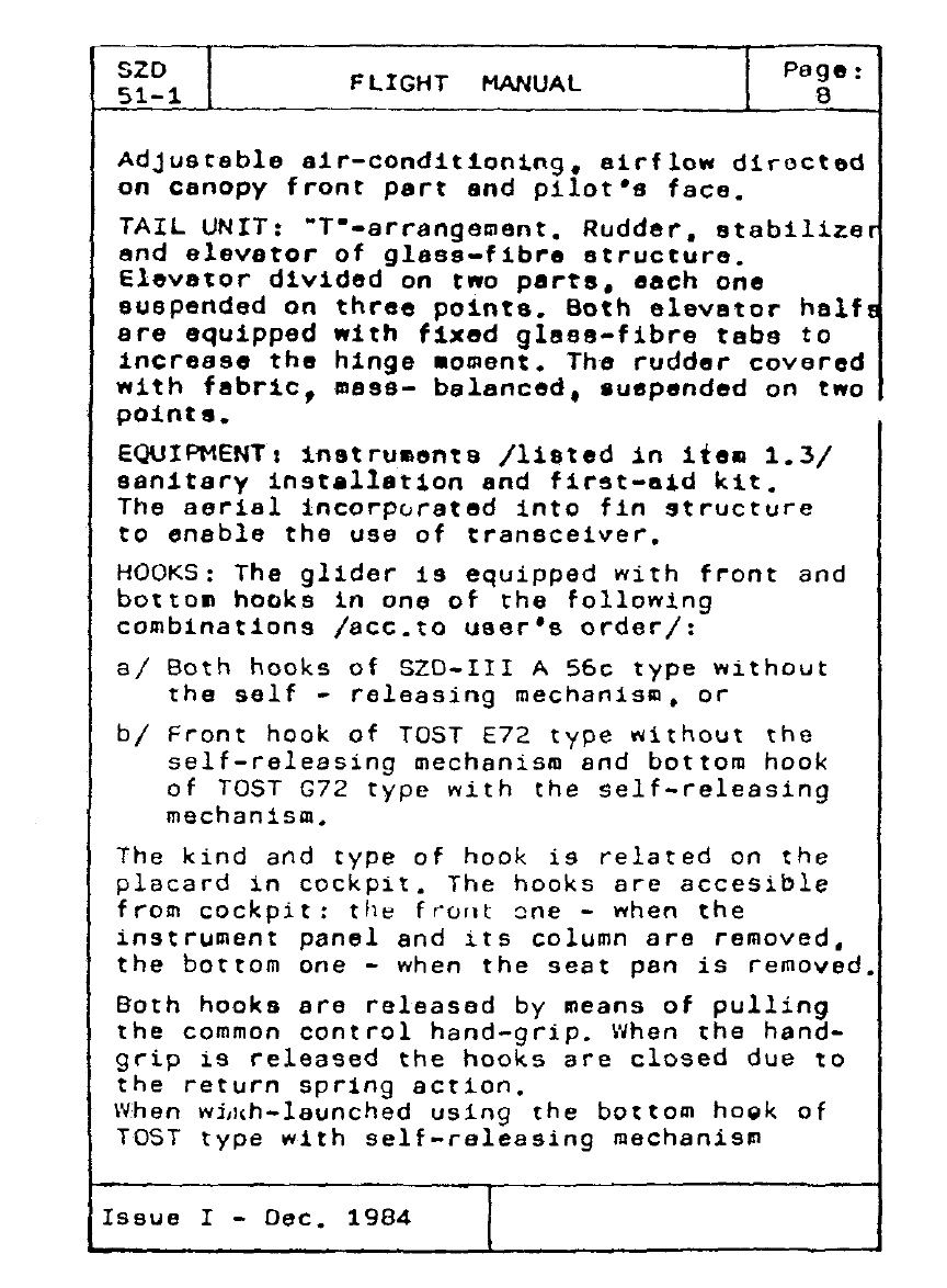
the
glider
releases
the
cable
auto111aticaly
when
the
cable
reaches
the
maximum
release
angle.
MOVABLE
EQUIPMENT:
assembling
lever,
screwdriver.
wrench
for
wheel
brake
adjustment
canvas
cover
for
canopy.
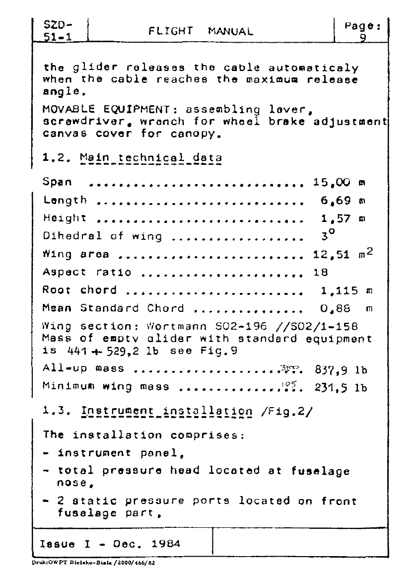
1.2.
Main
technical
data
-------------------
Sp;in .............................
15,00
'"
length
·~·····-····················
6•69
~
Height
• . • • •
..
. . • • • . . •
..
• .
..
• • . •
...
• • • .
..
1.57
m
Dihedral
of
wing
..••••••.••.••••••
3°
Wing
area
•..•••.•••.•.•••....•.•••
12.s1
m2
Aspect
rat
lo
.......................
18
Root
chord
.••••••••.••••••••••••••
1,115
m
Hean
Standard
Chord
• . . • • • • • • • • • • . •
0,88
m
Wing
section:
l'/ortmann
502-196
//502/1-158
Mass
of
emotv
alider
with
standard
equipment
is
441
+
529,2
lb
see
Fig.
9
All-vp
mass
...................
~
...•
;.~;:~.
M.
i Ill i I
05
in
mu
w
ng
mass
••••.•..••••••••.
The
installation
comprises:
-
1nstru~ent
panel,
837,9
lb
231,5
lb
-
total
pressure
heed
located
at
fuselage
nose,
- 2
static
pressure
ports
located
on
front
fuselage
part,
Ieeue
I -
Oec.
1984
Druk:OWPT
Diebko-Biala
/l.000/466/82: