Qlink LG250 User manual

IMPORTANT SAFETY INFORMATION
DRIVER AND PASSENGER
LG250 is designed only for one driver and one passenger. The total load must be within the limit specified
on the specification label.
ROAD CONDITION
The motorcycle is designed only for driving on paved roads.
READ THIS MANUAL CAREFULLY
Pay special attention to all the sentences or paragraphs marked with WARNING in this manual.
WARNING:
Means failure to follow the instructions will cause serious injury or death.
NOTICE:
Means that if the instructions in this manual are not observed, product damage or body injury may occur.
NOTE:
Provides you with the effective method of operation.
As the manual is considered as indispensable, it should be always kept with the driver for consultation.
USER'S MANUAL

TO OUR CUSTOMER
Thanks for choosing our motorcycle, LG250. For safe and pleasant driving, a complete understanding for all the
instructions in this manual is necessary. Your safety is not only ensured by your own alertness and your understanding
of all operations but also related to your understanding of the mechanic performance of the motorcycle. Making
inspections before driving and performing periodical maintenance are basic conditions for your safety.
When periodic maintenance or repair is necessary, please consult with our local dealer.
Wish you a pleasant drive.
The manufacturer reserves the rights to make improvement of the product at any time without prior
notice and without any obligation whatever.
USER'S MANUAL

CONTENTS
Traffic safety..............................................................1
Important information for safe driving...............2
Load .............................................................................3
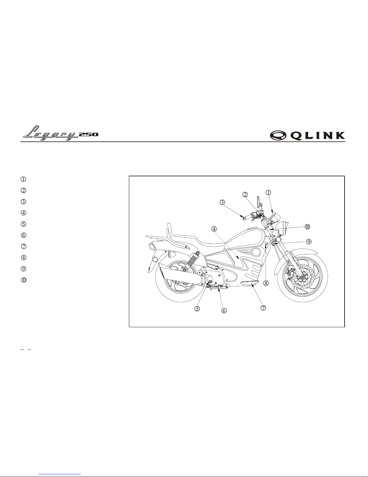
Parts and controls .....................................................4
Operation guide.........................................................7
Main switch ..............................................................7
Steering lock switch.................................................7
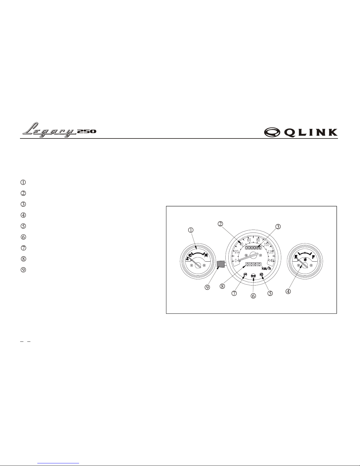
Temperature indicator..............................................8
Fuel gauge.................................................................8
Side stand indicator..................................................8
Trip reset button .......................................................8
Headlight illumination switch.................................9
Turning light switch .................................................9
Horn switch button ...................................................9
Ignition button..........................................................9
Headlight switch ......................................................9
Kill switch ................................................................9
Passing light switch.................................................9
Steering lock ..........................................................10
Rear foot pedal .......................................................10
Seat .........................................................................11
Audio control system .............................................12
USB plug................................................................12
Panel and buttons..................................................12
Main performance parameter..............................13
Output line functioning drawing ........................13
Inspection before driving .....................................14
Fuel capacity .........................................................14
Fuel tank capacity.................................................14
Checking engine oil level ....................................15
Brake ......................................................................16
Tire .........................................................................18
Starting the engine .................................................20
Driving the motorcycle..........................................21
Driving ...................................................................21
Braking ..................................................................22
Parking ...................................................................23
Anti-theft ...............................................................23
Maintenance interval.............................................24
Maintenance interval table..................................25
USER'S MANUAL

Maintenance ............................................................26
Air cleaner .............................................................26
Cooling system maintenance ..............................28
Radiator .............................................................28
Coolant type ......................................................28
Checking coolant capacity ..............................28
Engine oil...............................................................29
Recommend engine oil ....................................29
Viscosity ............................................................29
Replacing engine oil and cleaning oil screen ...30
Engine oil capacity..........................................30
Replace engine oil ...........................................30
Replace gearbox oil.........................................31
Spark plug..............................................................32
Battery....................................................................32
Replace the fuse....................................................33
Tools .......................................................................34
VIN number...........................................................35
Guideline for storage .............................................36
Technical parameter ..............................................38
Electrical diagram..................................................40
USER'S MANUAL
CONTENTS

TRAFFIC SAFETY
SAFETY CAN BE ENSURED ONLY BY DRIVER HIMSELF.
NOTICES:
A driver should always spend time on learning driving methods and technique before driving on the highway in less traffic
area.
1.Many motorcycle accidents occur due to that automobile driver cannot see the motorcycle driver. Therefore, the
motorcycle driver should make all his effort to be seen clearly by automobile driver.
For example:
Wear noticeable clothing.
Avoid driving carelessly.
2.Many accidents occur at the intersection, entrance or exit of parking lot and driveway. Therefore pay attention to the
above places.
3.Speeding is one of the main causes for many motorcycle accidents. Please obey the traffic rules and drive within the speed
limit.
4.Many motorcycle accidents occur due to insufficient experience. A new driver should comprehend each performance of
motorcycle before riding on the highway. Never lend motorcycle to inexperienced drivers.
5.Most injuries of motorcycle accidents are on head. Therefore please wear helmet and other protections, e.g. dust-tight
glasses, boots and thick coat.
6.Do not ride on the expressways. If inevitable, please be careful and drive safely.
7.Avoid driving on bumpy roads, which will result in losing control or damaging machine.
1
USER'S MANUAL

IMPORTANT INFORMATION FOR SAFE DRIVING
1.Before starting the engine, carefully inspect the motorcycle. (Refer to Page 14).
2.For safety, wear helmet as well as boots, gloves, dust-tight glasses and noticeable clothing;
3.The rear box or cargo box mounted by customer himself is for lightweight things only. If mounting cargo boxes on
two sides of motorcycles, please load equally on both and hold tightly in order not to move around when driving. For
detail, refer to page 3.
4.When driving, hold the steering handlebars and step on the footrest.
5.Practice on road in less traffic area and get familiar with motorcycle performance before driving on the roadway.
6.Turn on turn signals when turning or changing lane.
7.Do not drive on the road shoulder.
WARNING: This is a motorcycle of CVT transmission. Increase throttle ONLY after you are
ready to drive.
2
USER'S MANUAL

LOAD
WARNING:
Trunk or storage equipment etc., are for lightweight loads only.
Max. Load capacity: 331lbs.
Overload will affect the stability and controllability.
All the loads should be secured firmly.
Children or pets should not be carried on the bracket or trunk, e.g. dog or cat.
All the loads should not be oversized.
3
USER'S MANUAL

PARTS AND CONTROLS
THE ASSEMBLING POSITIONS OF CONTROLS
Panel and indicator
Audio box control system
Throttle grip
Air cleaner
Oil hole/Oil dip rod
Main stand
Floor rest
Main switch
Steering lock
VIN
The position marked with ……represents the invisible parts.
4
USER'S MANUAL

Rear Brake locking device
Left grip
Fuel tank lock
Fuel tank
Seat lock
Tool box
Coolant overflow
Radiator
VIN plate
Floor pedal
The position marked with ……represents the invisible parts.
5
USER'S MANUAL

PANEL AND INDICATOR
The controls of each indicator light and alarming light are integrated in the panel.
All the functions are instructed in the following pages.
Temperature indicator
Speedometer
Odometer
Fuel indicator
High beam indicator
Turning signal indicator (RH&LH)
Side stand parking indicator
Trip
Reset
6
USER'S MANUAL

OPERATION GUIDE
MAIN SWITCH
a) In this position, the engine will be shut down, all indicators will be
off, and the key can be taken out.
B)In this position, the engine and all indicators will be open, and the
key cannot be taken out.
STEERING LOCK SWITCH
Turn the handlebar to the upmost left, insert the key into steering
lock, turn it clockwise by 180 , and then take out the key.
Steering handlebar will be locked.
7
USER'S MANUAL

TEMPERATURE INDICATOR
The temperature indicator ① indicates the temperature of coolant. Side C indicates that the temperature is normal,
while the red area of side H indicates that the temperature is high. In that case shut down the engine until the coolant
temperature goes down.
In case the temperature frequently goes high, check coolant capacity or consult your local dealer.
NOTE: If the engine runs idle in extremely hot weather
for a long time the engine may be overheated.
Then shut down the engine for cooling.
SIDE STAND INDICATOR
When side stand is down, parking indicator ③ will be on, and engine will be stopped.
When side stand returns, parking indicator will be off, and engine can be started.
TRIP RESET BUTTON
Turn this button ④ counter clockwise to clear trip reading for next trip.
8
FUEL GAUGE
Fuel gauge ②indicates the remaining amount of the gasoline in the
fuel tank. “F” indicates the total amount of fuel is 4.5 Gallon
When the indicator reaches the first point of Red mark, fuel should
be refilled.
The Red mark indicates that the remaining amount of the gasoline
is only about 0.5 Gallon
USER'S MANUAL

HEADLIGHT ILLUMINATION SWITCH ①
Press button, and the high beam is on.
Press button, and the low beam is on.
TURNING LIGHT SWITCH ②
Press the switch to , and left turning light is on.
Press the switch to , and right turning light is on.
Press down the button, and turning light will be off.
HORN SWITCH BUTTON ③
Press the button, and the horn will sound.
IGNITION BUTTON ④
Press this button, and engine can be started (Refer to P20 for details).
HEADLIGHT SWITCH ⑤
The headlight switch consists of three positions: , and ;
: when the switch is at this position, headlight, the front pilot light, the rear pilot light and instrument light are on.
: when the switch is at this position, the front pilot light, the rear pilot light and instrument light are on.
: when the switch is at this position, headlight, the front pilot light, the rear pilot light and instrument light are off.
KILL SWITCH ⑥
Press button, and engine can be stopped..
Press button, and engine can be started.
OVERTAKE LIGHT SWITCH ⑦
Press this button, and headlight high beam will be on, which indicates the signal of passing to the vehicle in front.
9
USER'S MANUAL

10
STEERING LOCK
Turn the handlebar ① to the upmost left. Insert key into steering lock
and turn it clockwise by 180°(Refer to P7), and lock the steering
handle bar.Reverse the lock procedure to unlock.
NOTE: Before turning the key to LOCK, make sure to turn the
handlebar to the upmost left, or key may be damage.
REAR FOOT PEDAL
Passenger can unfold rear foot pedals (LH&RH) ③ to rest feet on.
If there is not a passenger on, fold the pedals for safety.
USER'S MANUAL

SEAT
Insert the key into the seat lock ①, turn it clockwise to open the seat.
Lift the rear part of seat ②, and move backward to separate the seat from front hook,
lift again, and the seat will be removed.
11
USER'S MANUAL

AUDIO CONTROL SYSTEM
USB PLUG
Remove the seat (Refer to P11), and toolbox cover ① can be seen.
Open toolbox cover, and a standard USB port can be seen.
Plug in flash memory stick, and enjoy music according to the
following instruction.
12
PANEL AND BUTTONS
1.PWR: POWER BUTTON. Press this button, and the light is on. Press
again, and the light is off.
2.FM: Press this button for radio. And the light will be on. (This light is off
when MP3 is working.)
3.SEEK: Press this button for seeking channels. When finding a channel,
the light winks, and the channel will be stored in “ ” and “ ”.
6channels could be stored.
Continue to seek channels by pressing this button again.
The button is invalid when the Mp3 is working.
4.MP3: Insert the flash memory stick and press this button, the MP3 player
will be on. And the light will be on.
If no U disk, there is no function and no light indicator.
5.MU: Press this button for MUTE, and light will be on.
Press again to cancel the MUTE mode, and the light will be off.
USER'S MANUAL

6. <</>>: Previous /Next button.
When MP3 is on, press this button for previous/next song
When radio is on, press this button for previous/next-stored channel.
7. VOL -: Press this button to reduce the volume.
8. VOL +: Press this button to increase the volume.
MAIM PERFORMANCE PARAMETER
FM radio MP3
Frequency range 87.5~108.0kHz Frequency response 10~20Hz
Noise limited sensitivity <15dB SNR <50 dB
SNR >50dB Text format in U disk Mp3
Distortion degree <1%
OUTPUT LINE FUNCTIONING DRAWING
NOTE:Never contact cathode line of sound
track (LH&RH) with earth, or sound
system may be damaged.
Output line functioning drawing
yellow
memo electrial
source anode
electrical source red
brown
left
speaker
brown/black
USB plug
wire plug
yellow
right
speaker
gray/black
USB
13
USER'S MANUAL

INSPECTION BEFORE DRIVING
To ensure the performance and safety, a routine inspection should be performed before drive.
FUEL CAPACITY
Once the fuel is insufficient, open the dust-proof cover ①, insert the key
into fuel tank lock②,turn it clockwise, take out fuel tank cap ③, and then
refill the fuel tank.
Also check any fuel leakage.
Fuel tank capacity: 4.5 Gallons
Turn the fuel tank lock ② clockwise after refilling, and press the fuel
tank cap to the filling port.
Take out the key, and fuel tank will be locked.
NOTE: Do not mix gasoline with engine oil.
NOTES: Use fuel with octane number over 93.
Be careful not to allow any dust, water or other
pollutants into fuel tank when refilling.
14
USER'S MANUAL

CHECKING ENGINE OIL LEVEL
1.Park the motorcycle on a level surface and support it with its main stand.
Remove oil dip rod ①, wipe it clean and insert it. Do not screw in.
2.If the oil level is at the lower limit ③, fill the crankcase with SAE15W-
40/SF engine oil till the oil level is up to the upper limit mark ②.
Then install oil dip rod. Check for any leakage.
15
WARNING: Gasoline is flammable and it may be exploded under certain conditions, therefore
refilling shall be done in a well-ventilated area after the engine has been stopped.
No smoking or lighting of spark is permitted in gas station or fuel storage area.
Do not over fill the tank. The amount of refilled fuel shall be kept below the fuel
mark. Tighten the cap after refilling.
Gasoline is poisonous. Faint or death may occur if gasoline is swallowed. Do keep
your skin away from gasoline. Do not breathe in the vapor of gasoline. Do keep it
away from children. If gasoline is swallowed, do not try to induce vomit, consult a
doctor immediately.
USER'S MANUAL

BRAKE
FRONT & REAR BRAKES
Check the brake fluid level: Brake fluid should be above the LOWER ① mark.
NOTICE: Use only DOT3 or DOT 4 brake fluid
FREE PLAY OF THE BRAKE LEVERS
Brake lever free play: 0.394~0.787" (at brake lever end)
NOTE: The free play of the brake lever should be 0.394 to 0.787".
If the free play is out of this range, please consult the local dealer.
16
USER'S MANUAL
This manual suits for next models
1
Table of contents
Other Qlink Motorcycle manuals