Qotom Q3217US User manual

QOTOM TECHNOLOGY LIMITED
1/ 11 www.qotom.net
Manual for Q3217US Mini Motherboard v1.0
Catalogue
I、Product Description.................................................................... 2
1. Brief Introduction .............................................................. 2
2. Version Specification............................................................ 2
3. Characteristics & Performances.................................................... 2
II、Product Overview ................................................................. 3
1. Front View.................................................................... 3
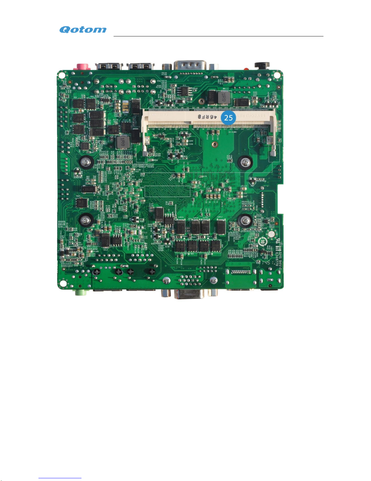
2. Back View .................................................................... 4
3. Connectors and Headers ......................................................... 4
III、Detailed Description of Connection Ports............................................... 6
1. Power Input Port ............................................................... 6
2. HDMI Connector............................................................... 6
3. VGA Connector................................................................ 6
4. 1000M LAN Port............................................................... 6
5. 4 * USB 2.0 Port ............................................................... 6
6. Audi Output Port ............................................................... 6
7. SATA 3.0 Port (6.0 Gb/s) ........................................................ 6
8. SATA Power Connector ......................................................... 7
9. PCI Express Half-Mini Card Slot (For WIFI and Bluetooth)............................ 7
10. PCI Express Full-Mini Card Slot (For MSATA SSD) .................................. 7
11. Intel Core 3217U Processor....................................................... 7
12. Intel HM76/HM75 Chipset ....................................................... 7
13. Serial Port .................................................................... 8
14. Power Switch with Power Indicator ................................................ 8
15. Microphone Input .............................................................. 8
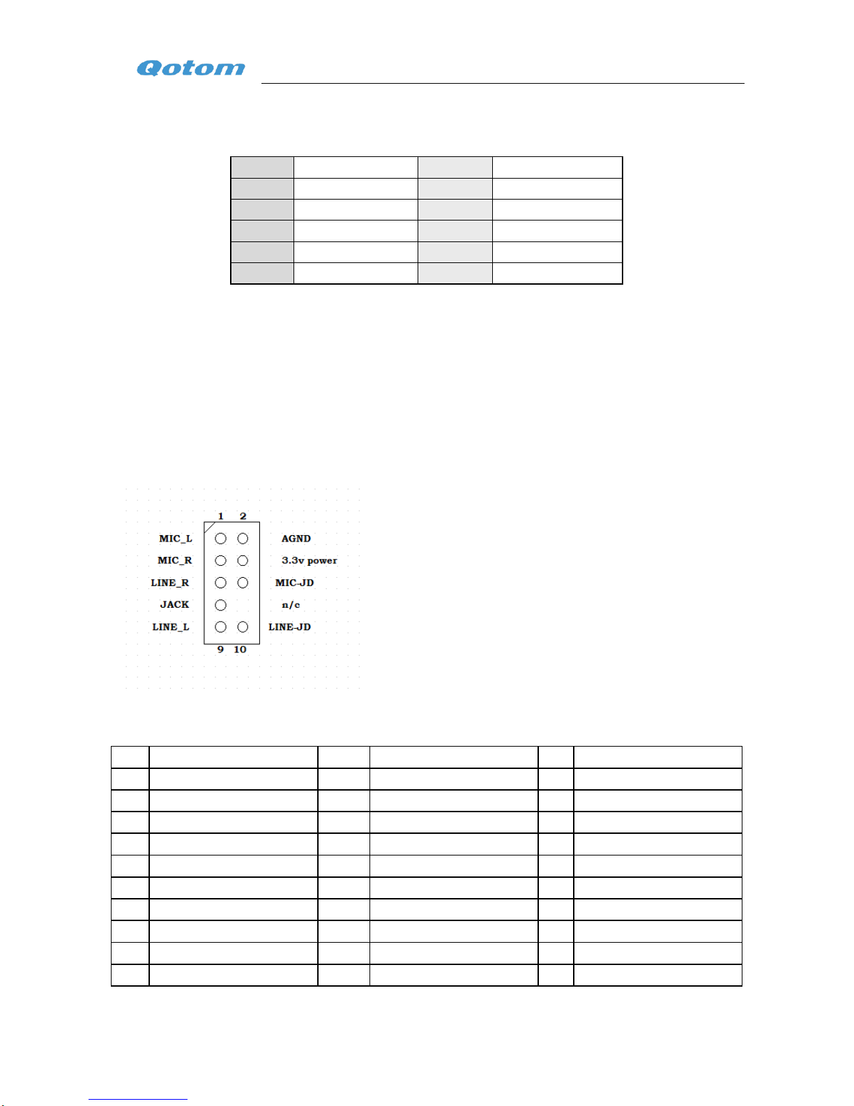
16. Extended Audio Input and Output Pin............................................... 8
17. LVDS Connector (optional)....................................................... 8
18. LCD Backlight Control (optional).................................................. 9
19. VDD_PANEL Pin for Selection of Power LVDS Backlight Inverter Voltage Selection
Header(optional) ...................................................................... 9
20. Extended USB Pin............................................................. 10
21. System Fan Header ............................................................ 10
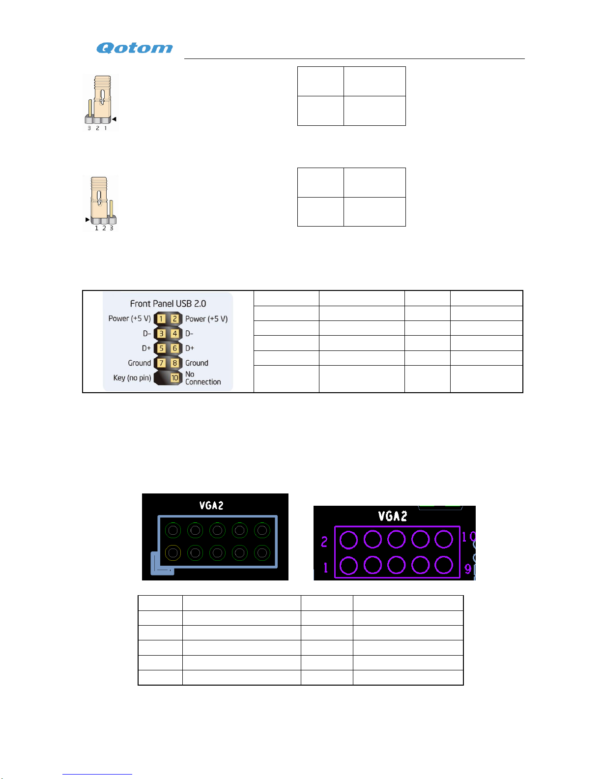
22. VGA Connection Pin........................................................... 10
23. Hard Drive Indicator Lamp ...................................................... 10
24. Extended Pin for External Panel .................................................. 11
25. Memory Slot ................................................................. 11

QOTOM TECHNOLOGY LIMITED
2/ 11 www.qotom.net
I、Product Description
1. Brief Introduction
Q3217US is a Standard Ultrathin Nano Mini-ITX motherboard designed based on the Intel IVB
Platform, with the size of 120mm x120mm. It adopts onboard Intel Core dual core 3217U 1.8G CPU.
2. Version Specification
Version NO.
Motherboard NO.
QTY of Network Card
QTY of USB Ports
V2.0
NM70EM01
2
4
3. Characteristics & Performances
1) Great reliability
With the adoption of the dual core 3217U ultra power consumption processor and switching mode power
supply, Q3217US motherboard can provide stable, sufficient and efficient power. The stability of the
motherboard is further guaranteed with the switching mode of power supply applied in memory, too. All of the
external devices of the motherboard is composed of some anti-static and jam-proof components which ensured
the operation of a stable and efficient system.
2) High Performance
It considerably increases performance of the platform by employing the NM70 chipset of Intel 7 Series and
SATA3.0
3) Full Support of BIOS
Support LVDS, Diskless booting and Wake on LAN
4) Working Condition
Working Temperature:-10℃~50℃
Working Humidity:5%~95%(Non-gel)

QOTOM TECHNOLOGY LIMITED
3/ 11 www.qotom.net
II、Product Overview
1. Front View

QOTOM TECHNOLOGY LIMITED
4/ 11 www.qotom.net
2. Back View
3. Connectors and Headers

QOTOM TECHNOLOGY LIMITED
5/ 11 www.qotom.net
Pin
Description
Signal Name
1
12V-19V DC IN
PWR1
2
HDMI Connector
HDMI
3
VGA Connector
VGA1
4
2 * 1000M LAN Ports
LAN1,LAN2
5
4 * USB 2.0 Ports
BACK_USB2, BACK_USB3
6
Audio Output Port
F_OUT
7
SATA 3.0 Port (6.0 Gb/s)
SATA1
8
SATA Power Connector
PWR_SATA1
9
PCI Express Half-Mini Slot(For WIFI&Bluetooth)
MINIPCIE2
10
PCI Express Full-Mini Slot(For MSATA SSD)
MINIPCIE1
11
Intel Core 3217U Processor
U1
12
Intel HM76/HM75 Chipset
U5
13
Serial Port
COM1
14
Power Switch with Power Indicator
BUTTON1
15
Microphone Input
F_MIC
16
Extended Audio Input and Output Pin
F_AUDIO
17
LVDS Connector
JLVDS
18
LCD Backlight Control
CNL_LVDS1
19
VDD_PANEL Pin for Selection of Power
LVDS Backlight inverter voltage selection header
ADJ_PWR1
PWR_LVDS
20
Extended USB Pin
F_USB1

QOTOM TECHNOLOGY LIMITED
6/ 11 www.qotom.net
21
System Fan Header
CPU_FAN1
22
VGA Connection Pin
VGA2
23
Hard Drive Indicator Lamp
LED1
24
Extended Pin on External Panel
PANEL1
25
Memory Slot
SO-DIMM1
III、Detailed Description of Connection Ports
1. Power Input Port
Increased reliability with intensive electrical socket outlet
12-19V power supply with wide voltage input, supporting 3A﹢current. Suitable for power adapter
(Internal: the positive pole, external: the negative pole) which has the outside diameter of 5.5mm and
inside diameter of 2.5mm.
2. HDMI Connector
Standard HDMI port
3. VGA Connector
Standard VGA port
4. 1000M LAN Port
Realtek RT8111E gigabit network, support diskless booting and Wake on LAN.
5. 4 * USB 2.0 Port
Universal USB2.0 port
6. Audi Output Port
Universal audio output port
7. SATA 3.0 Port (6.0 Gb/s)
Universal SATA3.0 port

QOTOM TECHNOLOGY LIMITED
7/ 11 www.qotom.net
8. SATA Power Connector
Special power interface, please ask for matching wire from the distributor.
Lead
1
2
3
4
Signal
5Vvoltage
5V voltage
Ground wire
Ground wire
Contact Spacing:2.0mm
PS:Standard SATA Power Connector Definition
9. PCI Express Half-Mini Card Slot (For WIFI and Bluetooth)
Half Mini PCIE port for extending WIFI and Bluetooth
10. PCI Express Full-Mini Card Slot (For MSATA SSD)
Universal MINI SATA port for accessing MSATA SSD
11. Intel Core 3217U Processor
Intel Core dual core 3217U, 1.8GHz, 3MB, with integrated Intel HD Graphics 4000
12. Intel HM76/HM75 Chipset
Intel HM76/HM75 Chipset

QOTOM TECHNOLOGY LIMITED
8/ 11 www.qotom.net
13. Serial Port
Standard RS232 port
Pin#
Signal
Pin#
Signal
1
DCD
2
RXD
3
TXD
4
DTR
5
GND
6
DSR
7
RTS
8
CTS
9
RI
10
14. Power Switch with Power Indicator
Power switch button with green power indicator lamp inside
15. Microphone Input
Universal microphone input port
16. Extended Audio Input and Output Pin
For accessing extended audio input and output pin
17. LVDS Connector (optional)
Pin
Signal
Pin
Signal
Pin
Signal
1
VDD_PANEL
11
LVDSA_CLK#( Negative )
21
LVDSB_DATA#2( Negative )
2
VDD_PANEL
12
LVDSA_CLK( Positive )
22
LVDSB_DATA2( Positive )
3
GND
13
LVDSA_DATA#3( Negative )
23
LVDSB_CLK#( Negative )
4
GND
14
LVDSA_DATA3( Positive )
24
LVDSB_CLK( Positive )
5
LVDSA_DATA#0( Negative )
15
GND
25
LVDSB_DATA#3( Negative )
6
LVDSA_DATA0( Positive )
16
GND
26
LVDSB_DATA3( Positive )
7
LVDSA_DATA#1( Negative )
17
LVDSB_DATA#0( Negative )
27
LVDS_DDCCLK
8
LVDSA_DATA1( Positive )
18
LVDSB_DATA0( Positive )
28
LVDS_DDCDAT
9
LVDSA_DATA#2( Negative )
19
LVDSB_DATA#1( Negative )
29
VDD_PANEL
10
LVDSA_DATA2( Positive )
20
LVDSB_DATA1( Positive )
30
LVDS_VCON

QOTOM TECHNOLOGY LIMITED
9/ 11 www.qotom.net
The above picture shows only the specification of 20 pins’socket, the actual socket is of 30 pins. The
interior corner on the upper right side is the first pin, and on the opposite of it is the second one, and so on.
All dimensions are given in millimeters.
18. LCD Backlight Control (optional)
Lead
1
2
3
4
5
Signal
12V voltage
5V voltage
Backlight
control
Backlight
Luminance control
Ground
Contact Spacing:2.0mm, the highlighted yellow one is the first pin.
19. VDD_PANEL Pin for Selection of Power LVDS Backlight Inverter Voltage Selection Header(optional)
PWR_LVDS Definition of Pin(VDD_PANEL Pin for Selection of Power)

QOTOM TECHNOLOGY LIMITED
10 / 11 www.qotom.net
1-2
3.3V
2-3
5V
ADJ_PWR1 Definition of Pin (Manual Control LVDS Backlight Inverter Voltage Selection Header)
1-2
5V
2-3
3.3V
20. Extended USB Pin
Pin for accessing extended USB2.0, extensible to 2 group
Lead
Signal
Lead
Signal
1
+5V DC
2
+5V DC
3
D-
4
D-
5
D+
6
D+
7
Ground
8
Ground
9
KEY (no pin)
10
No Connect
21. System Fan Header
For connecting fan of the system
22. VGA Connection Pin
Pin for accessing extended VGA port, standard VGA Signal output
Lead
Signal
Lead
Signal
1
VCC_PWR
2
RED
3
DDC_DATA
4
GREEN
5
DDC_CLK
6
BLUE
7
VSYNC
8
GND
9
HSYNC
10
GND
23. Hard Drive Indicator Lamp

QOTOM TECHNOLOGY LIMITED
11 / 11 www.qotom.net
Red color, for indicating the RW state
24. Extended Pin for External Panel
For accessing the power switch, reset button, power LED and HD LED.
25. Memory Slot
Only suitable for SO-DIMM of 1333Mhz or1600Mhz working frequency, maximum 8 GB single-sided
module
Table of contents
Other Qotom Motherboard manuals