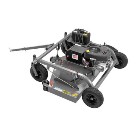
QuadBoss QBFC11544 User manual

44” FINISH CUT
TRAIL MOWER
OWNER’S
MANUAL
1602 CORPORATE DRIVE, WARRENSBURG MISSOURI 64093
PHONE 660 747 8183 FAX 660 747 8650
Manufacturing quality lawn care equipment since 1945
Assembly
Operation
Service and Adjustment
Repair Parts
Made In The
USA
REV 12 341
10699
QBFC11544
QBFC12544
Read and follow all
Safety Precautions
and Instructions
before operating this
equipment.
IMPORTANT
MODEL NO.
STARTING SERIAL # L112-341001

LIMITED WARRANTY
The manufacturer’ warranty to the original con umer purcha er i : Thi product i free from
defect in material and workman hip for a period of one (1) year from the date of purcha e
by the original con umer purcha er. We will repair or replace, at our di cretion, part found to
be defective due to material or workman hip. Thi warranty i ubject to the following
limitation and exclu ion :
1) Engine Warranty All engine utilized on our product ha a eparate warranty
extended to them by the individual engine manufacturer. Any
engine ervice difficulty i the re pon ibility of the engine
manufacturer and in no way i Swi her or it agent re pon ible
for the engine warranty. The Brigg & Stratton Engine Service
Hot Line i 1-800-233-3723.
2) Commercial U e The warranty period for any product u ed for commercial or
rental i limited to ninety day from the date of original purcha e.
3) Limitation Thi warranty applie only to product , which have been
properly a embled, adju ted, and operated in accordance with
the in truction contained within thi manual. Thi warranty
doe not apply to any product of Swi her that ha been ubject
to alteration, mi u e, abu e, improper a embly or in tallation,
hipping damage, or to normal wear of the product.
4) Exclu ion Excluded from thi warranty are normal wear, normal
adju tment , and normal maintenance.
In the event you have a claim under thi warranty, you mu t return the product to an
authorized ervice dealer. All tran portation charge , damage, or lo incurred during
tran portation of part ubmitted for replacement or repair under thi warranty hall be borne
by the purcha er. Should you have any que tion concerning thi warranty, plea e contact u
toll-free at 1-800-222-8183. The model number, erial number, date of purcha e, and the
name of the authorized Swi her dealer from whom you purcha ed the mower will be needed
before any warranty claim can be proce ed.
THIS WARRANTY DOES NOT APPLY TO ANY INCIDENTAL OR CONSEQUENTIAL
DAMAGES AND ANY IMPLIED WARRANTIES ARE LIMITED TO THE SAME TIME
PERIODS STATED HEREIN FOR ALL EXPRESSED WARRANTIES. Some tate do not
allow the limitation of con equential damage or limitation on how long an implied warranty
may la t, o the above limitation or exclu ion may not apply to you. Thi warranty give
you pecific legal right and you may have other right , which vary from tate-to- tate. Thi i
a limited warranty a defined by the Magnu on-Mo Act of 1975.
2

This Safety Alert Symbol indicates important messages in this
manual. When you see this symbol, carefully read the message that
follows and be alert to the possibility of personal injury.
Read this manual completely. This machine can amputate hands, feet, and
throw objects. Failure to observe the following safety instructions could
result in serious injury or death.
SAFETY PRECAUTIONS
• Read the manual. Learn to operate thi machine afely.
•Alway di connect the park plug wire and place the wire where it
cannot contact the park plug, to prevent accidental tarting of the engine
when etting up, tran porting, adju ting or making repair .
• Keep all hield and guard in place.
• Under tand the peed, teering and tability of thi machine. Know
the po ition and operation of all control before you operate thi
machine. Check all of the control in a afe area before tarting to work
with thi machine.
• Clear the area of object uch a rock , toy , wire, etc. that can be
picked up and thrown by the blade.
• Allow only re pon ible adult who are familiar with the e in truction
to operate thi machine. Never allow children to operate this machine.
• Be ure the area i clear of other people before mowing. Be aware of the
mower di charge direction and do not point at anyone. Stop the machine
if anyone enter the mowing area. Children are often attracted to the
machine and the mowing activity. Never assume that children will
remain where you last saw them.Keep children under the watchful care
of another re pon ible adult.
•No riders!
3

• Turn off the blade when not mowing. Before leaving the machine, turn off the
blade and top the engine.
• Watch for traffic when operating near or cro ing roadway .
• Do not operate the mower if the mower ha been dropped or damaged
in any manner or if it vibrate exce ively. Exce ive vibration i an
indication of damage. Repair mower a nece ary.
• Dre properly. Do not operate the mower when barefoot or
wearing open andal . Wear only olid hoe with good traction when
mowing.
• Do not operate the machine while under the influence of alcohol or
drug .
• Operate elf-propelled machine up and down lope . There i
ignificant ri k of overturn when operating acro lope . Operate walk-
behind machine acro lope . There i a ignificant ri k of lipping
under a walk-behind machine when operating up and down lope . Do not
operate on lope greater than 15 degree .
• Never tamper with afety device . Check their proper operation
regularly.
• Stop and in pect the equipment if you trike an object. Repair, if
nece ary, before re tarting.
• Never make adju tment or repair with the engine running.
• Mower blade are harp and can cut. Wrap the blade or wear glove ,
and u e extra caution when ervicing them.
4
• Do not put hand or feet near or under rotating part . Keep clear of
the di charge opening at all time .
• Do not mow in rever e. Always look down and behind before and while
backing.

OD36 Deflector Decal
OD45 Warning Decal
OD29 Danger Decal
Engine Serial #
OD11 No Step Decal
OD15 Void Warranty Decal
OD33 Speed Decal
OD55 Triangle Danger Decal
(All four deck corners)
TrailMower Serial #
SAFETY DECALS
Replace decal immediately if damaged. Order by part number from Swi her.
OD99125 Medium Swisher
Logo White Decal
(Not Pictured)
OD99127-44" Deck White Decal
(Not Pictured)
OD99127-44" Deck White Decal
(Not Pictured)
5
OD99161 QUADBOSS Decal

OPERATING YOUR TRAIL MOWER
INTENDED USE
The 44” Trail Mower i de igned to produce a quality fini h cut on lawn , golf cour e ,
etc. It i not intended to clear bru h or cut apling . Your Trail Mower hould be
towed behind an ATV, golf cart, lawn tractor, or other approved vehicle. It i not
de igned for peed exceeding 5 MPH. WARNING: To avoid eriou injury,
operate your mower up and down the face of lope , NEVER acro the face. DO
NOT MOW SLOPES GREATER THAN 15 DEGREES! (See attached guide for
ighting lope .)
ATTACHING TRAIL MOWER TO TOW VEHICLE
• Back vehicle up to de ired towing po ition.
• Off et the Trail Mower to the ide oppo ite the tow vehicle di charge (if any).
Thi prevent the tow vehicle from throwing gra into Trail Mower engine.
• If tow vehicle ha a ball hitch, the ball mu t be removed before hitch can be
fa tened.
• Attach hitch to the tow vehicle with hitch pin (H11). Make certain the hitch
pin goe completely through and i clipped to prevent accidental eparation.
• Securely attach afety tether (6736) to tow vehicle and to the Trail Mower
toggle witch located on right ide of the engine. The afety tether will top the
Trail Mower engine either manually or if the two hould become eparated. It is
very important that the safety tether is securely attached to both the toggle
switch and to the tow vehicle. See Fig 3, pg 15.
The operation of any mower can produce foreign object to be thrown into the
eye , re ulting in evere eye damage. Alway wear certified afety gla e or
wide-vi ion afety goggle over pectacle before taring any cutting machine
and while operating uch a machine.
The operation of any cutter produce ound wave that are damaging to the
human ear. Ear protection i recommended.
CAUTION!
Tragic accident can occur if the operator i not alert to the pre ence of
children. Children are often attracted to the machine and the mowing
activity. Never assume that children will remain where you last saw
them.
TRANSPORTING MOWER
• Stop Trail Mower.
• Place Trail Mower deck in it highe t po ition.
• When tran porting without the u e of a tow vehicle, remove park plug
wire and place it where it cannot contact the park plug.
6

• Set vehicle parking brake or chock wheel to prevent accidental rolling.
• Start engine properly.
• Slowly engage blade control.
• In a afe environment, i.e. no children, allow blade to rotate and engine to
idle for 5 minute . Thi break in the belt and the engine.
• Stop mower properly.
ENGAGING BLADES
The Trail Mower will not tart if the blade lever i in the “ENGAGED” po ition.
• Engage blade by rotating blade lever into the “ENGAGED” po ition.
• Rotate blade lever in oppo ite direction to di engage blade.
• The dual braking y tem i applied when the blade become di engaged. It i
de igned to bring the blade to quick top (approximately 7 econd ). Each
Trail Mower brake y tem ha been te ted and calibrated. For afety, the
con umer hould not alter the braking y tem.
STARTING THE ENGINE
See engine manufacturer’ recommendation for the type and amount of oil and fuel
u ed. Trail Mower equipped with an electric tart engine will need a battery ( old
eparately). Swi her recommend u ing a tandard “12N12A” battery.
• Make ure the tow vehicle parking brake i et, mower i level, and blade are
di engaged. Engine mu t be level to accurately check and fill oil. Do not overfill.
• Check park plug wire, oil, and fuel.
• Check all electrical connection for buildup or debri .
• Make ure toggle witch i not turned “OFF” and afety tether i attached.
• Set engine throttle to “RUN” po ition.
• Move the choke lever to the “ON” po ition (cold engine only).
• With feet clear of mower deck, turn key witch to the “START” po ition; relea e
when engine begin to run (12 volt model ). Recoil model mu t u e pull-rope.
Pull rope with a ingle fluid motion.
• Set engine throttle at maximum RPM.
• Allow engine to run a few moment before engaging blade .
BREAKING IN YOUR MOWER
CAUTION!
SHUT OFF MOWER ENGINE AND REMOVE SPARK PLUG WIRE FROM
SPARK PLUG BEFORE MAKING ANY ADJUSTMENTS TO THE MOWER.
7
IMPORTANT: This engine is not equipped with a spark arrester muffler. It is a violation of
California Public Resource Code Section 444 to use or operate the engine on any forest-covered,
brush-covered, or grass-covered land. Other states or federal areas may have similar laws.

• There i approximately 1 ½” to 4 ½” of height adju tment.
• Rotate height adju t crank handle in a clockwi e direction to lift the mower
deck. A counter-clockwi e direction i u ed to lower the mower deck.
• Graduated cale are for reference only, not the actual cutter height.
• Bring tow vehicle to a complete top, hut off engine, and et parking brake.
• Di engage blade .
• Manually hut toggle witch and/or key witch to their “OFF” po ition .
• Alway remember to remove key to avoid irre pon ible u age (electric tart
model only).
• Adju t the cutting height.
• Double check vehicle to mower attachment.
• Start mower engine and et throttle to “FAST” for be t cutting performance.
• Slowly engage blade clutch lever.
• Carefully mount vehicle and tart mowing at a low travel peed.
• Swi her recommend if the tow vehicle i equipped with a mid-mount mower
to overlap the cut approximately 6”. Thi may vary depending on mowing
terrain, ob tacle , and/or tow vehicle. Alway keep SAFETY the fir t priority.
• If the tow vehicle i not equipped with a mid-mount mower, we till
recommend off etting the mower o that the tow vehicle doe not cru h the
gra .
• Make adju tment while Trail Mower i not running.
• Remove hairpin NB127 from clevi pin 18842 o L-hitch 18829 can
be repo itioned.
• Rai e or lower hitch ection to obtain proper front to back adju tment.
• In ert clevi pin in the de ired hitch po ition and ecure with hairpin .
MOWER HEIGHT ADJUSTMENT
• Make adju tment while Trail Mower i not running.
FRONT TO BACK ADJUSTMENT
For be t cutting re ult , the mowing deck hould be rai ed to ½” to ¾” higher in
the rear.
TOW HITCH OFFSET
Thi Trail Mower ha been de igned to operate off et from the center of the tow
vehicle or con ecutively with another Trail Mower, providing additional cutting
width. When off etting the mower do o to the ide oppo ite the di charge of the tow
vehicle.
STARTING TO MOW
STOPPING THE MOWING SESSION
8

SUGGESTED MOWING PRACTICES
• Operate mower engine at full throttle to a ure the be t cutting performance and
maximum material di charge.
• Allow wet gra to dry. Wet gra will clump and collect under the mowing deck.
• Mowing hould be tarted with tow vehicle in low gear and increa ed only a afe
mowing condition permit. Mowing peed hould not exceed 5 MPH.
• The average lawn hould be cut to approximately 2.5” during the cool ea on and to
over 3” during the hot month .
• For a healthier lawn and better ae thetic , your lawn hould be mowed often and
after moderate growth.
• When cutting high or den e gra area go lowly. Some area may need to be
mowed twice. The econd cut hould be at 90 degree to the fir t, if po ible.
•Mowing thick or high grass: Rai e rear of deck to ½” to ¾” above front of the
deck. See “FRONT TO BACK ADJUSTMENT”. When mowing thick or high gra ,
it i recommended to cut area twice. The fir t at a higher etting and the econd at the
de ired lawn height.
•Creating a manicured lawn: Never cut more than 1/3 of the gra height in one
cutting.
GENERAL TROUBLE SHOOTING
The mower i not cutting level.
• Check air pre ure of all tire ; make ure they are equal. See tire for
maximum inflation.
• Make certain blade are in talled identically, without the engine running.
The engine will not tart.
• Di engage blade , turn toggle witch to “OFF” po ition, check battery and all
other electrical connection , and in pect park plug and wire.
• Contact engine manufacturer or qualified mechanic.
Engine run poorly.
• See engine manual.
• Check the throttle adju ter.
• Replace fuel, clean fuel filter and fuel line.
• Check park plug and gap.
Mower bounce exce ively while towing.
• Decrea e tire pre ure.
• Tow at a lower peed.
IF PROBLEMS PERSIST HAVE A QUALIFIED MECHANIC SERVICE THE
MOWER. NEVER ATTEMPT TO MAKE AN ADJUSTMENT THAT YOU
ARE NOT SURE IS CORRECT. DOING SO CAN CAUSE OTHER
PROBLEMS.
9

MOWER MAINTENANCE
GENERAL RECOMMENDATIONS
The warranty on thi Trail Mower doe not cover item that have been ubjected to
operator abu e or negligence. To receive full value from the warranty, operator mu t
maintain unit a in tructed in thi manual.
Some adju tment will need to be made periodically to maintain your unit properly.
All adju tment in thi manual hould be checked at lea t once each ea on.
BEFORE EACH USE
• Check engine oil level on a level urface. Check twice to en ure an accurate
reading.
• Check condition of air filter; clean and replace a nece ary.
• Check blade operation; keep blade in good condition.
• Check for loo e fa tener and tighten them a needed.
AFTER EACH USE
• Keep blade harp.
• Remove fre h gra clipping with garden ho e.
• Hardened gra clipping on under ide hould be craped out with a putty
knife.
• Keep fluid at proper level .
• Cover unit to prevent rain or other debri buildup. Definitely cover the
engine.
BEFORE AND/OR AFTER EACH SEASON
• Replace the park plug.
• Clean or replace the air filter.
• A new park plug and clean air filter a ure proper air-fuel mixture and help
your engine run better and la t longer.
• Check blade and belt for wear. Replace a nece ary.
• Change the oil.
• See engine manufacturer’ recommendation for ervicing.
STORAGE RECOMMENDATIONS
CAUTION! Do not tore engine indoor or other poorly ventilated area. Keep
engine away from ga appliance and water heater where fume could contact
open flame, pilot light , or park .
If engine is to be stored for 30 or more days, prepare unit as follows:
· Drain fuel out ide into an approved container.
· Start engine properly and run until unit i out of fuel.
· Let engine cool.
· Remove remaining ga oline from carburetor and fuel tank to prevent gum
depo it from forming within the engine. Gum depo it can cau e
malfunction in the engine.
· Store mower with blade di engaged to prevent belt from being permanently
tretched.
10

BLADE CARE AND SERVICE
For be t re ult mower blade mu t be kept harp. The blade can be harpened with a
few troke of a file or grinding wheel. Do not attempt to harpen blade while they are
on the mower. Disconnect spark plug wire before servicing unit.
Important: Replace blades that have been damaged or deeply nicked.
Important: Check blade and spindle hardware on a regular basis to make sure
nuts are tight.
Only a qualified mechanic should make any
adjustments, disassembly or other kind of repairs.
REPAIR PARTS
Your 44” Trail Mower ha been produced with component de igned pecific to thi
machine. Although tandard V-belt , pring , bearing , blade , pulley , hardware, etc.
look imilar to part u ed on other machinery, they may in ome ca e be made of a
different con truction and/or material .
NOTES:______________________________________________________________
_____________________________________________________________________
_____________________________________________________________________
_____________________________________________________________________
_____________________________________________________________________
_____________________________________________________________________
_____________________________________________________________________
_____________________________________________________________________
_____________________________________________________________________
_____________________________________________________________________
_____________________________________________________________________
_____________________________________________________________________
_____________________________________________________________________
_____________________________________________________________________
_____________________________________________________________________
_____________________________________________________________________
_____________________________________________________________________
_____________________________________________________________________
_____________________________________________________________________
_____________________________________________________________________
_____________________________________________________________________
_____________________________________________________________________
_____________________________________________________________________
_____________________________________________________________________
_____________________________________________________________________
_____________________________________________________________________
_____________________________________________________________________
_____________________________________________________________________
_____________________________________________________________________
11

DESCRIPTION PART #
Harness - Wiring, Recoil 10638
Module MOD1
Harness - Wiring, 1 V 10 35
Harness - Toggle/Ground Wire Assembly 9090
Solenoid - 3 Pole 100 004
Cable - Battery, 10" Red; Positive BCSR
Cable - Battery, 10" Black; Negative BCS
Box - Battery 10 31*
Pad - Battery BATPAD
Cable - Battery 19.5", Red BCL
Boot - Battery BCBT
Battery - Hold Down BHOLD
BATTERY (1 N1 A) RECOMMENDED** N/A
12 VOLT START MODELS
RECOIL START MODELS
FC44 RECOIL START FC44 12 VOLT START
Fig. 1
PARTS NOT SHOWN
WIRING CONFIGURATIONS
12
When ordering repla ement parts
* = USE PAINT CODE: GT=GRAY TK=BLACK
**Battery Sold Separately

Fig. 2
PARTS BREAKDOWN
When ordering repla ement parts
* = USE PAINT CODE: GT=GRAY TK=BLACK
ITEM # DESCRIPTION PART #
1 Cover - Belt 10599*
Bolt - 1/4- 0 X 1/ NB114
3 Base - Motor 4517*
4 Hitch - Weldment 45 5*
5 Bolt - Serrated Flange 5/16-18 X 3/4 NB596
6 Nut - Serrated Flange 5/16-18 NB170
7 Bracket - Roller Right 4016*
8 Bolt - 3/8-16 X 5 1/ NB575
9 Bracket - Anti Scalp Roller 10634*
10 Roller - Anti-Scalp 3/8 ID AS001
11 Screw - .31 -18 X .75 6X 49
1 Axle - Assembly Weldment 10596*
13 Plate - Front Skirt 4518*
14 Plate - Back Skirt 4519*
15 Nut - Nyloc 3/8-16 NB18
ITEM # DESCRIPTION PART #
16 Nut - Nyloc 1/ -13 NB 81
17 Bolt - 1/ -13 X 1/ NB588
18 Bracket - Roller, Left 4015*
19 Roller - Anti-Scalp 1/ ID AS003
0 Nut - Jam, 1/ -13 NB118
1 Tire/Wheel - 3/4 Bearing 15 X 6 X 6 F44157LVK
Pin - Cotter, 1/8 X 1 NB1 6
3 Chute - Discharge Weldment 10598*
4 Spring - Torsion 166X34
5 Nut - Nyloc 5/16-18 NB181
6 Mount - Grass Chute 6030*
7 Bolt - 5/16-18 X 8 3/4 NB136
8 Bearing - OI Lite 1/ " 0 1008
9 Washer - USS Flat, 1/ NB555
30 Bolt - 1/ -13 X 1 1/ 10046
31 Deck - Weldment 10586*
13

Fig. 3
ENGINE SET UP
Fig. 4
BLADE SET UP
ITEM # DESCRIPTION PART # QTY
1 Engine - 11.5HP N/A 1
1 Engine - 12.5HP 12V N/A 1
2 Module - Engine MOD1** 1
3 Valve - Oil Drain 16000 1
4 Bolt - Serr Flange, 5/16-18 X1 1/4 NB253 4
5 Tether - Assembly 6736 1
6 Bracket - Switch 4483Z 1
7 Switch - Toggle, Single Pole 685SP 1
8 Nut - Serr Flange 5/16-18 NB170 4
9 Spacer - Engine Pulley BB105S 1
10 Key Stock - 1/4 X1 9031 1
11 Pulley - Engine, 4.25" BB105 1
12 Spacer - Lower Engine Pulley BB105SL 1
13 Washer - Belleville 7/16 X1 1/4 699 1
14 Bolt - 7/16-20 X1, Nylock NB452N 1
ITEM # DESCRIPTION PART # QTY
1 Nut - Jam 3/4-16 NB175 1
2 Washer - Belleville .760 X1.5 AS155 1
3 Pulley - Blade 4 1/2" B4104 1
4 Washer - 3/4 X1 1/4 NB179 3
5 Bearing - Blade B98 2
6 Shaft - Blade 4.25" 9076 1
7 Bolt - Serr Flange 1/4-20 X3/4 NB690 2
8 Nut - Serr Flange, 1/4-20 NB524 4
9 Housing - Bearing 9057* 1
10 Bolt - Serr Flange 1/4-20 X1 1/4 15359 1
11 Bolt - Serr Flange 1/4-20X2 1/2 NB208 1
12 Washer - 3/4 X 1 3/4 B98W 1
13 Nut - Lock, Two Way 3/8-24 NB216 2
14 Plate - Blade Mount 9008 1
15 Washer - Belleville .413 X.945 NB607 1
16 Blade - 22" 9005 1
17 Bolt - 3/8-24 X1, Nylock NB238N 1
18 Bolt - 3/8-24 X1 NB238 2
14
** MOD1 is not used with 12V engine.
Slide plastic tube on tether 6736
snug against toggle switch 685SP.
When ordering replacement parts
* = USE PAINT CODE: GT=GRAY TK=BLACK
Blade Driver Assembly
(Includes shaft, housing and bearings)
Part # 9018

ITEM # DESCRIPTION PART # QTY
1 Bolt - 1/ -13 X 5 NB155 1
Bolt - Spade, 5/16-18 X 10.5 NB 60 1
3 Nut - Nyloc 5/16-18 NB181 1
4 Pivot - Engage 4578* 1
5 Nut - 5/16-18 NB 10Z
6 Knob - Shift B19BLACK 1
7 Pivot - Engagement 4548* 1
8 Nut - Serr Flange 5/16-18 NB170 1
9 Nut - Jam Lock, 1/ -13 NB1 1
10 Bolt - 5/16-18 X 1 NB501 1
11 Nut - Serr Flange, 1/4- 0 NB5 4
1 Bolt - Serr Flange, 1/4- 0 X 3/4 NB690
13 Engagement - Standoff 4547* 1
15
ITEM # DESCRIPTION PART # QTY
1 Rod - Crank ES 14 1
Nut - Push, 5/16 NB117
3 Knob - Height Adjustment H7K 1
4 Rod - Height Adj 5/8-11 X 13-1/16 4006 1
5 Washer - Mach 1/ NB177 6
6 Block - Single Point Pivot 4007* 1
7 Bolt - 1/ -13 X 1 1/ 10046
8 Nut - Jam, 1/ -13 NB118 1
9
Washer - Belleville .515 X1.50 X.115
10635
10 Nut - Nyloc 1/ -13 NB 81 1
Fig. 6
HEIGHT ADJUSTMENT
When ordering repla ement parts
* = USE PAINT CODE: GT=GRAY TK=BLACK
Fig. 5
STANDARD ENGAGE

1
2
3
4
5
2
6
7
8
ITEM # DESCRIPTION PART #
1 Belt - 74" 4 0
Spring T SM
3 Bracket - Spring Tension 4593*
4 Brake - Arm Sub-Assembly, Left 10591
5 Brake - Arm Sub Assembly, Right 10590
6 Switch - Return to Neutral 3695
7 Bracket - Switch 4301*
8 Bolt - Serr Flange 5/16-18 X 3/4 NB596
8
Nut - Serr Flange 5/16-18
NB170
16
Fig. 7
Tension Assembly
ITEM # DESCRIPTION PART #
1 Nut - Way Lock 3/8-16 NB 80
Washer - 3/8 NB 7
3 Pulley - Idler B5 7
4 Bolt - 1/4- 0 X NB 18
5 Bolt - 3/8-16 X 1 1/4 NB618
6 Washer - Idler 6040Z
7 Nut - Nyloc 1/4- 0 NB180
8 Brake - Link 453
9 Nut - Serrated Flange 1/4- 0 NB5 4
10 Eyebolt - 1/4- 0 X 3/4 V139EB
11 Arm - Idler 4530*
1 Bushing - Idler 6037
13 Nut - Nyloc 3/8-16 NB18
14 Nut - Nyloc 5/16-18 NB181
15 Spring - Idler Tension 44
16 Nut - Serrated Flange 5/16-18 NB170
17 Bolt - Serrated Flange 5/16-18 X1 1/4 NB 53
18 Bolt - Spade, 5/16-18 X 10.5 NB 60
19 Nut - 5/16-18 NB 10Z
0 Bolt - 3/8-16 X 1 1/ NB107
When ordering repla ement parts
* = USE PAINT CODE: GT=GRAY TK=BLACK
Fig. 8
Belt / Brake Configuration

Fig. 9
BRAKE ARM CONFIGURATIONS
17
Item # Des ription Part # Qty
1 Arm - Brake 10589* 1
Eyebolt - 1/4- 0 X 3/4 V139EB 1
3 Nut - Nylock 1/4- 0 NB180 1
4 Nut - Serr Flange 1/4- 0 NB5 4
5 Bolt - HTC 1/4- 0 X 1 1/ NB16
6 Nut - Kep 10- 4 NB17 1
7 Pad - Brake 9039 1
8 Screw - 10- 4 X 1 1/ NB710 1
RIGHT ASSEMBLY PART # 10590
LEFT ASSEMBLY PART # 10591
Item # Des ription Part # Qty
1 Arm - Brake 10589* 1
Nut - Serr Flange 1/4- 0 NB5 4
3 Bolt - 1/4- 0 X NB 18 1
4 Nut - Kep 10- 4 NB17 1
5 Pad - Brake 9039 1
6 Screw - 10- 4 X 1 1/ NB710 1
When ordering repla ement parts
* = USE PAINT CODE: GT=GRAY TK=BLACK

Fig. 10
HITCH ASSEMBLY
When ordering repla ement parts
* = USE PAINT CODE: GT=GRAY TK=BLACK 18
ITEM #
DESCRIPTION
PART #
QTY.
1
Weldment - "L" Hitch
188 9*
1
Tube - Hitch
1883 *
1
3
Tube - Hitch Elbow
18833*
1
4
Washer - SAE Flat 3/8
NB 7
8
5
Bolt - 3/8-16x 1/ HCC GR5
NB 1
6
Nut - Nyloc 3/8-16
NB18
4
7
Plug - 1.75x10⁻¹⁴ga SQ Tube
18834
8
Pin - Clevis, 3/8x .5; ZY
1884
1
9
Pin - Hair, #39
NB1 7
5
10
Pin - Clevis, 3/8x3.75; ZY
18843
11
Pin - Safety Hitch 3/8x 1/ ZY
H11
1
1 Bolt - 3/8-16x3 HCC GR5 ZY NB150
13 Spacer - Straight Hitch 18974* 1

RECOMMENDED HITCH
CONFIGURATIONS AND
POSITIONS
19

20
This manual suits for next models
1
Table of contents
Other QuadBoss Lawn Mower manuals
Popular Lawn Mower manuals by other brands

Toro
Toro Recycler 20357 Operator's manual

Toro
Toro Groundsmaster 4500-D Operator's manual

Craftsman
Craftsman 917.250051 owner's manual

Locke
Locke MP-148, MP-160, MP-172 Operator's manual

POWERTEC Garden
POWERTEC Garden Eco Wheeler 460/5IN1 R Translation of the original instructions

MTD
MTD 130-410 owner's guide