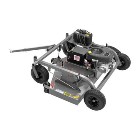
QuadBoss QBFC2066 User manual

66” FINISH CUT
TRAIL MOWER
OWNER’S
MANUAL
1602 CORPORATE DRIVE, WARRENSBURG, MISSOURI 64093
PHONE 660 747 8183 FAX 660 747 8650
MODEL NO.
QBFC2066
Manufacturing quality lawn care equipment since 1945
Assembly
Operation
Service and Adjustment
Repair Parts
Made In The
USA
REV 12 341
Read and follow all
Safety Precautions
and Instructions
before operating this
equipment.
IMPORTANT
13318
STARTING SERIAL #:
L112-341001

LIMITED WARRANTY
The manufacturer’s warranty t the riginal c nsumer purchaser is: This pr duct is
free fr m defects in materials and w rkmanship f r a peri d f ne (1) year fr m the
date f purchase by the riginal c nsumer purchaser. As required by § 1060.120, the
fuel system related c mp nents, which have been certified t this equipment by SAI
are t be free f defects in material and w rkmanship f r a peri d f tw (2) years
fr m the date f purchase by the riginal c nsumer purchaser. We will repair r
replace, at ur discreti n, parts f und t be defective due t materials r w rkmanship.
This warranty is subject t the f ll wing limitati ns and exclusi ns:
1) Engine Warranty All engines utilized n ur pr ducts have a separate
warranty extended t them by the individual engine
manufacturer. Any engine service difficulty is the
resp nsibility f the engine manufacturer and in n way
is Swisher r its agents resp nsible f r the engine
warranty. The Briggs & Stratt n Engine Service H t
Line is 1-800-233-3723.
2) C mmercial Use The warranty peri d f r this pr duct used f r
c mmercial r rental is limited t ninety (90) days fr m
the date f riginal purchase.
3) Limitati ns This warranty applies nly t pr ducts which have been
pr perly assembled, adjusted, and perated in
acc rdance with the instructi ns c ntained within this
manual. This warranty d es n t apply t any pr duct f
Swisher that has been subject t alterati n, misuse,
abuse, impr per assembly r installati n, shipping
damage, r t n rmal wear f the pr duct.
4) Exclusi ns Excluded fr m this warranty are n rmal wear, n rmal
adjustments, and n rmal maintenance.
In the event y u have a claim under this warranty, y u must return the pr duct t an
auth rized service dealer. All transp rtati n charges, damage, r l ss incurred during
transp rtati n f parts submitted f r replacement r repair under this warranty shall be
b rne by the purchaser. Sh uld y u have any questi ns c ncerning this warranty,
please c ntact us t ll-free at 1-800-222-8183. The m del number, serial number, date
f purchase, and the name f the auth rized Swisher dealer fr m wh m y u purchased
the m wer will be needed bef re any warranty claim can be pr cessed.
THIS WARRANTY DOES NOT APPLY TO ANY INCIDENTAL OR CONSEQUENTIAL DAMAGES AND
ANY IMPLIED WARRANTIES ARE LIMITED TO THE SAME TIME PERIODS STATED HEREIN FOR ALL
EXPRESSED WARRANTIES. S me states d n t all w the limitati n f c nsequential damages r limitati ns n
h w l ng an implied warranty may last, s the ab ve limitati ns r exclusi ns may n t apply t y u. This warranty
gives y u specific legal rights and y u may have ther rights, which vary fr m state-t -state. This is a limited
warranty as defined by the Magnus n-M ss Act f 1975.
2

SAFETY PRECAUTIONS
• Read the manual. Learn t perate this machine safely.
• Always disc nnect the spark plug wire and place the wire where it cann t c ntact the spark plug, t prevent
accidental starting the engine when setting up, transp rting, adjusting r making repairs.
• Keep all shields and guards in place.
• Understand the speed, steering and stability f this machine. Kn w the p siti ns and perati ns f all
c ntr ls bef re y u perate this machine. Check all f the c ntr ls in a safe area bef re starting t w rk
with this machine.
• All w nly resp nsible adults wh are familiar with these instructi ns t perate this machine. Never all w
children t perate this machine.
• Clear the area f bjects such as r cks, t ys, wire, etc. that can be picked up and thr wn by the blade.
• Be sure the area is clear f ther pe ple bef re m wing. Be aware f the m wer discharge directi n and d
n t p int at any ne. St p the machine if any ne enters the m wing area. Children are ften attracted t the
machine and the m wing activity. Never assume that children will remain where you last saw them.
Keep children under the watchful care f an ther resp nsible adult.
• No riders!
• D n t put hands r feet near r under r tating parts. Keep clear f the discharge pening at all times.
• D n t m w in reverse. Always l k d wn and behind bef re and while backing.
• Turn ff the blades when n t m wing. Bef re leaving the machine, turn ff the blades and st p the engine.
• Watch f r traffic when perating near r cr ssing r adways.
• D n t perate the m wer if it has been dr pped r damaged in any manner r if the m wer vibrates
excessively. Excessive vibrati n is an indicati n f damage. Repair m wer as necessary.
• Dress pr perly. D n t perate the m wer when baref t r wearing pen sandals. Wear nly s lid sh es
with g d tracti n when m wing.
• D n t perate the machine while under the influence f alc h l r drugs.
• Operate self-pr pelled machines up and d wn sl pes. There is significant risk f verturns when perating
acr ss sl pes. Operate walk-behind machines acr ss sl pes. There is a significant risk f slipping under a
walk-behind machine when perating up and d wn sl pes. D n t perate n sl pes greater than 15
degrees.
• Never tamper with safety devices. Check their pr per perati n regularly.
• St p and inspect the equipment if y u strike an bject. Repair, if necessary, bef re restarting.
• Never make adjustments r repairs with the engine running.
• M wer blades are sharp and can cut. Wrap the blades r wear gl ves, and use extra cauti n when servicing
them.
This Safety Alert Symbol indicates important messages in this
manual. When you see this symbol, carefully read the message that
follows and be alert to the possibility of personal injury.
Read this manual completely. This machine can amputate hands, feet, and throw
objects. Failure to observe the following safety instructions could result in serious
injury or death.
3

4
SAFETY DECALS
Replace decals immediately if damaged.Order by part number fr m Swisher
OD45- Warning Decal
OD11- N step Decal
OD55- Triangle Danger Decal
OD33- Speed Decal
OD29- Danger Decal
OD43- Flying Debris Decal

REQUIRED ASSEMBLY
FRONT WHEEL CASTER ASSEMBLY
1. Rem ve single nut and washers fr m caster shaft.
2. Place ne washer n the shaft f the caster/wheel sub-assembly.
3. Slide same shaft thr ugh the bearing/frame with wheel t wards the gr und.
4. Place the ther washer n the shaft; it sh uld be resting n the t p bearing.
5. Thread nyl c jam nut nt shaft.
6. Tighten nut snuggly, making sure shaft threads enter the nyl c f the nut.
Over tightening this nut will bind caster.
7. Repeat pr cess f r ther fr nt side.
REAR WHEEL ASSEMBLY
1. Rem ve c tter pin fr m axle.
2. Slide washer (NB149) if necessary and wheel (valve stem ut)
nt axle and replace c tter
pin.
3. Bend c tter pin s it will n t fall ut.
4. Repeat pr cess f r ther wheel.
OFFSET & CENTER TOW HITCH BAR ASSEMBLY
1. Lay ut parts acc rding t the diagram.
2. Insert part 661A int part 12543 and pin with the hitch pin (H11).
3. Insert part 661 int part 661A. Ch se fr m the 3 h les t set the desired hitch length.
Pin with a hitch pin.
4. Part 12543 slides int the fr nt tube f the frame. Ch se fr m the 5 h les t arrange
desired ffset. Pin with a hitch pin (H11).
5. Eliminate step 3 f r hitching fr m the center bracket. Only ne meth d can be used at a
time.
5
CENTER TOWING
POSITION
OFFSET TOWING
POSITION
Bent Pin, Hair Pin
and Receiver
supplied by thers.
Existing Rear Hitch.
ATV or Utility
Vehicle Attachment
Instructions
661
661A
12543
H11

OPERATING YOUR TRAIL MOWER
INTENDED USE
This Trail M wer is designed t pr duce a quality finish cut n lawns, g lf c urses, etc. It is
not designed t clear brush r cut saplings. Y ur Trail M wer sh uld be t wed behind an
ATV, a g lf cart, lawn tract r, r similar appr ved vehicle. It is n t meant f r speeds
exceeding 5 mph.
ATTACHING TRAILMOWER TO TOW VEHICLE
• Place m wer behind vehicle and back vehicle up t desired attaching p siti n.
• When ffsetting Trail M wer d s t side pp site the discharge f the t w vehicle.
• B lt swivel hitch (H10) t vehicle t w receiver.
• Attach t w hitch (661) t the swivel hitch with hitch pin (H11). Make certain hitch
pin g es c mpletely thr ugh each piece and is clipped t prevent accidental
separati n.
• Attach red safety tether (H9C) t b th the t wing vehicle and t the TrailM wer
t ggle switch (685SP), l cated n the thr ttle h using (6013). Its purp se is t
manually st p m wer engine r t st p m wer engine in case the tw machines
bec me separated. (See M t r Base Detail #20).
• It is extremely important the safety tether is secured properly to both the toggle
switch and the towing vehicle.
STARTING THE ENGINE
See engine manufacturer’s instructi ns f r the type and am unt f il and fuel used. Trail
M wers with electric start engines will need a battery (s ld separately). Swisher
rec mmends using a standard “U 1 R” lawn & garden battery.
• Engine must be level t accurately check and fill il. D n t verfill.
The perati n f any m wer can pr duce f reign bjects t be thr wn int the
eyes, resulting in severe eye damage. Always wear certified safety glasses r
wide-visi n safety g ggles ver spectacles bef re starting any cutting machine and
while perating such a machine.
The perati n f any cutter pr duces s und waves that are damaging t the
human ear. Ear pr tecti n is rec mmended.
CAUTION!
Tragic accidents can ccur if the perat r is n t alert t the presence f
children. Children are ften attracted t the machine and the m wing
activity. Never assume that children will remain where you last saw them.
6

•
Make sure the t w vehicle parking brake is set, m wer is level, and blades are disengaged.
• Check spark plug wire, il, and fuel.
• Check all electrical c nnecti ns (See Schematics).
• Make sure t ggle switch is turned “ON” and the red tether is pr perly attached.
• Set engine idle t “CHOKE” p siti n.
• With feet clear f m wer deck, turn key switch t the “START” p siti n and release when
engine begins t run.
• Set engine idle at desired RPM.
BREAKING IN YOUR MOWER
• Set vehicle parking brake r ch ck wheels t prevent accidental r lling.
• Start engine pr perly.
• Sl wly, engage blade c ntr l.
• In a safe envir nment, i.e. n children, all w blades t r tate and engine t idle f r 5
minutes. This breaks in the belts and the engine.
• St p m wer pr perly.
MOWER HEIGHT ADJUSTMENT
• Adjust while m wer is not running.
• The cutting range is appr ximately 1.5” t 4.5”. The height has been measured fr m the
gr und t the blade tip with ut the engine running.
• R tate height adjust crank handles (H7N) in a cl ckwise directi n
t lift the m wer deck. A
c unter-cl ckwise directi n is used t l wer the m wer deck.
• Make sure the height adjustment is the same at side crank handles. F r best results, see
“SUGGESTED PRACTICE” secti n. Graduated scales are f r reference nly, n t the
actual cutter height.
• Place crank handle in a retracted p siti n t maintain height adjustment.
STARTING TO MOW
• Adjust the cutting height.
• D uble check vehicle t m wer attachment.
• Start m wer engine pr perly.
• Sl wly, activate the blade engage lever by r tating it f rward and left until the lever l cks
int place.
• Carefully m unt t w vehicle and start m wing sl wly.
STOPPING THE MOWING SESSION
• Pull safety tether t shut t ggle switch “OFF”. If the engine fails t st p r if the safety
tether has bec me in perable, then use Alternative St pping Meth d.
CAUTION!
SHUT OFF MOWER ENGINE AND REMOVE SPARK PLUG WIRE FROM
SPARK PLUG BEFORE MAKING ANY ADJUSTMENTS TO THE MOWER.
7

ALTERNATIVE STOPPING METHOD
• Bring vehicle t c mplete st p, shut ff engine, and set parking brake.
• Disengage blade engage lever (6008).
• Manually shut t ggle and key switches t their “OFF” p siti ns.
• Always remember t rem ve keys t av id irresp nsible usage.
TRANSPORTING MOWER
• St p m wer pr perly.
• Place m wer deck in its highest p siti n.
• If transp rting with ut the use f a t w vehicle, rem ve spark plug wire and place
where it cann t c ntact the spark plug.
SUGGESTED MOWING PRACTICES
• Operate m wer engine at full thr ttle t assure the best cutting perf rmance and
maximum material discharge.
• All w wet grass t dry. Clumps f wet grass will c llect under the m wing deck.
• M wing sh uld be started with t w vehicle in l w gear and increased nly as safe
m wing c nditi ns permit. This speed sh uld n t exceed 5 mph.
•
The average lawn sh uld be cut t appr ximately 2.5” during the c l seas n and t
ver 3” during the h t m nths.
• F r a healthier lawn and better aesthetics, y ur lawn sh uld be m wed ften and
after m derate gr wth.
• When cutting high r dense grass areas g sl wly. S me areas may need t be
m wed twice. The sec nd cut sh uld be at 90 degrees t the first, if p ssible.
• Mowing thick or high grass. Raise rear height crank handles t .5”-.75” a
b ve the
ther tw handles.
• Creating a manicured lawn. L wer rear height crank handle t .25”-.5” bel w
fr nt f deck. This all ws grass blades t be cut twice. It als c ntinually cuts
clippings t pr duce a mulching effect.
GENERAL TROUBLE SHOOTING
• The m wer is n t cutting level.
o Level deck, making sure the side crank-handles are equal.
o Check air pressure f all tires; make sure they are equal and t
manufacturers specificati ns.
o Examine blades f r damage, while m wer engine is n t running.
• The engine will n t start.
o Di
sengage blades, turn t ggle switch t “ON” p siti n, check battery and all
ther electrical c nnecti ns, and inspect spark plug and wire.
o Check f r fuel in the engine.
• Engine runs p rly.
o See engine manual.
o Check thr ttle adjuster.
o Replace fuel, clean fuel filter and fuel line.
IF PROBLEMS PERSIST HAVE A QUALIFIED MECHANIC SERVICE THE
MOWER. NEVER ATTEMPT TO MAKE AN ADJUSTMENT THAT YOU ARE
NOT SURE IS CORRECT. DOING SO CAN CAUSE OTHER PROBLEMS.
8

MOWER MAINTENANCE
GENERAL RECOMMENDATIONS
The warranty n this Trail M wer d es n t c ver items that have been subjected t perat r abuse r negligence.
T receive full value fr m the warranty, perat r must maintain unit as instructed in this manual.
S me adjustments will need t be made peri dically t maintain y ur unit pr perly.
All adjustments in this manual sh uld be checked at least nce each seas n.
BEFORE EACH USE
• Check engine il level n a level surface. Check twice t insure an accurate reading.
• Check c nditi n f air filter; clean and replace as necessary.
• Check blade perati n; keep blades in g d c nditi n.
• Check f r l se fasteners and tighten them as needed.
AFTER EACH USE
• Keep blades sharp.
• Rem ve fresh grass clippings with garden h se.
• Grass clippings can harden t the underside sh uld be scraped ut with a putty knife.
• Keep fluids at pr per levels.
• C ver unit t prevent rain r ther debris buildup. Definitely c ver the engine.
BEFORE AND/OR AFTER EACH SEASON
• Replace the spark plug.
• Clean r replace the air filter.
• A new spark plug and clean air filter assure pr per air-fuel mixture and help y ur engine run better and
last l nger.
• Check blades and belts f r wear. Replace as necessary.
STORAGE RECOMMENDATIONS
CAUTION! D n t st re engine ind rs r ther p rly ventilated area. Keep engine away fr m gas
appliances where fumes c uld c ntact pen flame, pil t lights, r sparks.
If engine is to be stored for 30 or more days, prepare unit as follows:
• Drain fuel utside int an appr ved c ntainer.
• Start engine pr perly and run until unit is ut f fuel.
• Let engine c l.
• Rem ve remaining gas line fr m carburet r and fuel tank t prevent gum dep sits fr m f rming
within the engine. Gum dep sits can cause malfuncti n in the engine.
• St re m wer with blades disengaged t prevent belts fr m being permanently stretched.
BLADE CARE AND SERVICE
F r best results blades must be kept sharp. The blades can be sharpened with a few str kes f a file r grinding
wheel. D n t attempt t sharpen blades while they are n the m wer. Disconnect spark plug wire before
servicing unit.
Important: Replace blades that have been damaged or deeply nicked.
Important: Check blade and spindle hardware on a regular basis to make sure nuts are tight.
Only a qualified mechanic sh uld be used f r any
adjustments, disassembly r ther kind f repairs.
9

FRAME DETAIL
10
Item # Description Part #
1 Tongue Hitch 661*
2 Solid Stock Hitch 661A*
3 Bushing 10579
4 Safet Hitch Pin H11
5 3/4 - 16 N loc Nut NB122
6 Caster Fork 665*
7 Washer NB195
8 Wheel Spacer 663L
9 5/8 - 11 2 Wa Lock Nut NB595
10 Wheel/Tire/Bearing F4157WK
11 5/8 - 11 X 7 Bolt NB624
12 Extension Hitch 12543*
13 Frame 12513*
14 Bearing B98
15 Cotter Pin NB126
16 Rear Axle 12526
17 Height Adjustment Handle H7N
18 Height Adjustment Tube Weldment 10059
19 5/16 PAL Nut NB276
20 Plastic Knob H7K
21 Crank Arm ES214
22 5/8 ID X 1 OD 14 Ga Washer NB149
23 5/8 ID X 1 OD 10 Ga Washer NB178
24 E e Bolt 10038
25 Caster/Wheel Assembl 18430
NOT SHOWN Height Indicator Decal OD41
Item # Description Part #
1 Ubolt - SQ 3/8-16 X 2.437 X 3 12447
2 Nut - N loc, 1/4-20 ZY NB180
3 Nut - N loc 3/8-16 ZY NB182
4 Mount - For EPA/CARB Gas Tank 18331*
5 Fuel Tank - 2.5 Gallon, Carb 18214
6 Cap - Thread Vented, 2.5 Gal. Tank 18134
7 Bracket - Fuel Tank 18225
8 Bolt - Serr Flange 1/4-20 X 1 3/4 18236
9 Washer - SAE Flat 1/4 NB274
Item # Description Part #
1 Carbon Canister - 2.50 Gallon, 3/16 Line 18224
2 Cable Tie - Carbon Canister 18219
3 Nut - 10-24 N lon Lock 024900
4 Bracket - Carbon Canister, ZT 17127
5 Screw - 10-24 X 3/4 Phil Truss Head ZP 024203
Only included on “CA” Models (California Compliant)
When rdering replacement parts
*USE PAINT CODE: GT=GRAY TK=BLACK

MOWER DECK DETAIL
BA50
(50”)
12527
(130”)
11
Item # Description Part #
1 Belt Cover 12523*
2 Grass Chute 9902*
3 Chute Bracket 6030*
4 Anti-Scalp Roller AS001
5 Deck 12520*
6 Torsion Spring 166X34
Swa Bar Left 3665
Swa Bar Right 3664
12 Deck Idler 6055
13 3/8 - 16 X 1 1/4 Bolt NB618
14 Spacer 6040Z
15 Idler Arm 6054*
16 Bushing 6037
17 Nut - N loc 5/16-18 ZY NB181
18 Idler Pulle B527
19 3/8 - 16 2 Wa Lock Nut NB280
20 3/8 Washer NB272
21 Nut - N loc 3/8-16 ZY NB182
22 5/16 - 18 E e Bolt NB315
23 Spring TZ2S
24 5/16 - 18 Nut NB173
25 5/16 - 18 X 1 Bolt NB501
26 3/8 - 16 X 1 1/2 Bolt NB107
27 5/16 - 18 Serr Flange Nut NB170
28 Batter Box 6112*
29 Bolt/Nut for Batter Box NB690/NB524
32 Bolt - HCC 5/16-18 X 8 1/2 GR2 ZP NB136
33 Bolt - 3/8-16 X 5 1/2 GR5 ZY NB575
34 Bolt/Nut for Frame Mount NB509/NB281
35 Bolt - Carriage, 3/8-16 X 4 NB707
36 Bracket - Rear Roller 10775
37 Bolt - Carriage, 3/8-16 X 4 ZY NB707
38 Bolt - Carriage 5/16-18 X 3/4 GR5 ZY 10216
39 Nut - Lock, 5/16-18 ZY 2 Wa NB558
11
BELT IDLER DETAIL
BELT CONFIGURATION
When rdering replacement parts
*USE PAINT CODE: GT=GRAY TK=BLACK

Slide plastic tube snug
against toggle switch.
MOTOR BASE DETAIL
12
IDLER DETAIL
Item No.
Description Part #
1 Heat Shield 6052*
2 Throttle 686N
3 Toggle Switch 685SP
4 Control Console 10737*
5 Ignition Switch 3623
6 Motorbase 12521*
7 Belt Guide 14869
8 Belt Guide 6000
9 Top Idler Assembl 10735
10 5/16 - 18 N loc Nut NB181
11 Plastic Knob
B19BLACK
12 Engage Lever 10727*
13 Engage Rod Assembl 4422/10636YZ
14 3/8 - 16 X 1 1/2 Bolt NB107
15 Washer NB272
16 Idler Pulle B527
17 3/8 - 16 2 Wa Lock Nut NB280
18 Top Idler Weldment 6009*
19 5/16 - 18 X 1 Bolt NB501
20 Safet Tether H9C
21 Return Spring BRS6
22 Nut - Jam 5/16-18 ZY NB173
23 Washer - SAE 5/16 ZY NB275
24 Nut - Serrated Flange 5/16-18 ZY NB170
25 Nut - Flange, 1/4-20 NB524
26 Nut - HX 1/4-20 ZY NB139
27 Bolt - Serr Flng, 5/16-18 X 3/4 NB596
28 Nut - Jam Lock, 1/2-13 2-Wa NB121
20
29 Pivot - Engage 4578*
30 Bolt - HCC 1/4-20 X 1 GR5 ZY NB102
31 Bolt - 1/4-20 X 3/4 GR5 ZY NB250
32 Screw - Phil Truss 8-32 X 1/2 ZY NB197
33 Nut - Kep 8-32 ZY NB201
34 Nut - Ke Switch 9087
35 Bolt - Shoulder, 1/2 X 1-9/16 NB220
36 Nut - N loc 3/8-16 ZY NB182
PA TS NOT SHOWN
Washer Kev Switch 9088
Throttle Knob 686K
10 Amp Fuse AS069
WIRING HARNESS [BRIGGS] WH60B2
BATTERY [ U 1 R ] NA
BATTERY CABLE- RED BCSR
BATTERY CABLE- BLACK BCLB
SOLENOID 1002004
BATTERY STRAP BHOLD
KEYS KSK
BATTERY CABLE BOOTS BCBT
When rdering replacement parts
*USE PAINT CODE: GT=GRAY TK=BLACK

ENGINE DETAIL*
13
Item # Description Part #
1 UPPER SPACER 689L
2 5-1/2'' ENGINE PULLY 688
3 1/4/ X 1'' KEY STOCK 9031
4 LOWER SPACER 689S
5 3/8 BELLEVILLE WASHER 699
6 FLAT WASHER TR150W
3/8-24 X 1BOLT [BRIGGS ] NB452N
7/16-20 X 1 BLOT [TECUMSEH ] NB238N
8 5/16-18 X 1-3/4 BOLT NB515
9 5/16 USS WASHER NB275
10 5/16-18 Flge NUT NB170
11 BELT GUIDE 6000
12 5/16-18 X 1 1/4 FLG.BOLT NB253
13 5/16-18 NYLOCK NUT NB181
NOT SHOWN Valve - Oil Drain 16000
NOT SHOWN Oil Drain Valve Cap AS123
7
*Engine shown is for reference onl
Out r Blad
Driv r
Configuration
Item # Description Part #
27 Center Shaft 9075
28 Blade Bearing B98
29 Bearing Housing 10539*
30 Pulle Spacer 6065PM
31 Blade Mount Plate 9008
32 22 1/2 ''Blade 12509
33 Blade Pulle - 5.5" 6114
34 SP Washer Bellvl. PLN .413 X .945 X .118 NB607
35 3/4 ID X 1 1/4 OD 18 GA Washer NB179
36 3/4-16 Jam Nut NB175
37 3/8-24 X 1 1/4 HCC GR5 ZP NB238
38 3/8-24 X 1 Engine Bolt Locktite NB238N
39 1/4-20 X 3/4'' Serr Flange Bolt NB690
40 1/4-20 Serr.Flange Nut NB524
41 3/8-24 2-Wa Lock Nut NB216
42 L&R Shaft 9077
43 Belleville Washer AS155
44 Flat Washer B98W
C nt r Blad
Driv r
Configuration
When rdering replacement parts
*USE PAINT CODE: GT=GRAY TK=BLACK

WIRING SCHEMATICS
14

NOTES:
______________________________________________________________________
______________________________________________________________________
______________________________________________________________________
______________________________________________________________________
______________________________________________________________________
______________________________________________________________________
______________________________________________________________________
______________________________________________________________________
______________________________________________________________________
______________________________________________________________________
______________________________________________________________________
______________________________________________________________________
______________________________________________________________________
______________________________________________________________________
______________________________________________________________________
______________________________________________________________________
______________________________________________________________________
______________________________________________________________________
______________________________________________________________________
______________________________________________________________________
______________________________________________________________________
______________________________________________________________________
______________________________________________________________________
______________________________________________________________________
______________________________________________________________________
______________________________________________________________________
______________________________________________________________________
______________________________________________________________________
______________________________________________________________________
______________________________________________________________________
______________________________________________________________________
______________________________________________________________________
______________________________________________________________________
15

OWNER’S
MANUAL
MODEL NO.
QBFC2066
HOW TO ORDER
REPAIR PARTS:
66” FINISH CUT
TRAIL MOWER
Each m wer has its wn m del number. Each engine has its
wn m del number. The m del number f r the m wer will be
f und n the right hand side f the frame at the wheel bracket.
The m del number f r the engine will be f und n the t p f
the bl wer fan h using.
All m wer parts listed herein may be rdered directly fr m
Swisher r y ur nearest Swisher dealer.
All engine parts may be rdered fr m the nearest dealer f the
engine supplied with y ur m wer
.
C l r cann t be guaranteed n service parts.
WHEN ORDERING PARTS, PLEASE HAVE THE
FOLLOWING INFORMATION AVAILABLE:
* PRODUCT – FC66 TRAIL MOWER
* SERIAL NUMBER - _______________
* MODEL NUMBER - _______________
* ENGINE MODEL NUMBER - _______________
TYPE - _______________
* PART NUMBER
* PART DESCRIPTION
TELEPHONE - 1-800-222-8183
FAX - 1-660-747-8650
SWISHER
1602 CORPORATE DRIVE
WARRENSBURG, MO 64093
SWISHER
IMPORTANT
Read and follow all
Safety Precautions
and Instructions
before operating this
equipment.
Table of contents
Other QuadBoss Lawn Mower manuals