Trouble Shooting
This power amplifier has protection features to prevent any damages from misuse or faulty conditions.
If the unit senses excessive heat ,short circuited speaders or overload, the protection indicators will light,
and the system will be turned off.ln order to check the occurred problem,you should turn all levels down
and all power off and carefully check the installation for wiring mistakes or short.
lf the amplifier shuts down due to excessive heat, the protection indicators will not light :simply allow
time for the unit to cool.
Before removing your amplifier, refer to the list below and follow the suggested procedures.
Always test the speakers and their wires first.
AMPLIFIER IS NOT POWERED UP
Check that there is battery power on the +12V terminal.
Check that remote terminal has at least 14.4V DC remote connection.
Check a good ground connection. Check all fuses.
Check the protection LED is not lit.
PROTECTION LED ILLUMINATES WHEN AMPLIFER IS POWERED UP
Check shorts on speaker wires.
Remove speaker wires and reset the amplifier. lf the protection LED still comes on,
then the amplifier is faulty.
FUSE BLOWING
Check that the minimum speaker impedance is correct.
Check short on power cable and vehicle chassis.
OVERHEATING
Check that the minimum speaker impedance is correct.
Check speaker shorts .
Check that there is a good airflow around the amplifier.
SOUND TOO LOW -DISTORTED SOUND
Check that the input level control is set to match the output level of the unit.
Check the head unit volume.
Check speaker shorts.
Check that crossover frequencies have been properly set.
HIGH HISS-ENGINE NOISE IN SPEAKERS
Check a good ground and for speaker shorts.
Disconnect all RCA inputs from the amplifier. lf hiss/noise disappears, check it with a good
RCA interconnect. Then check the component driving the amplifier.
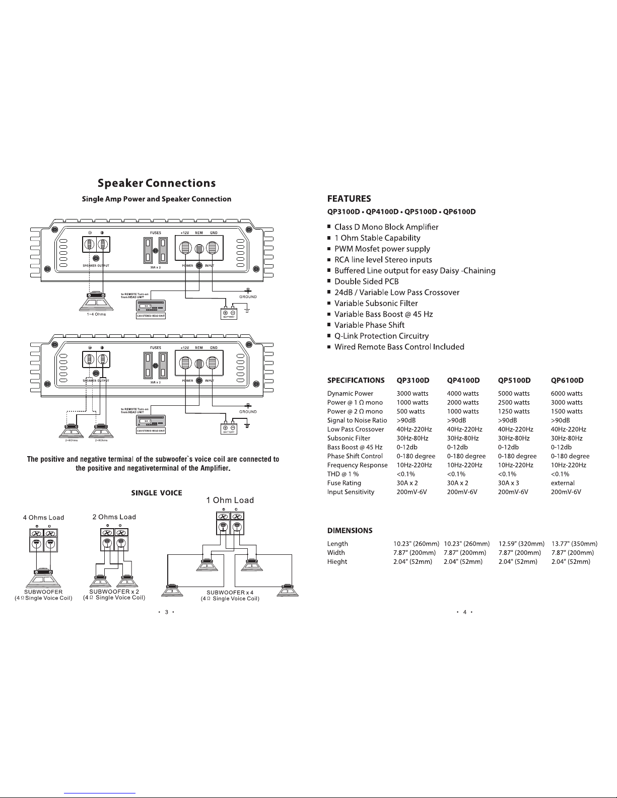
+12V REM GND
POWER INPUT
FUSES
SPEAKER OUTPUT
30
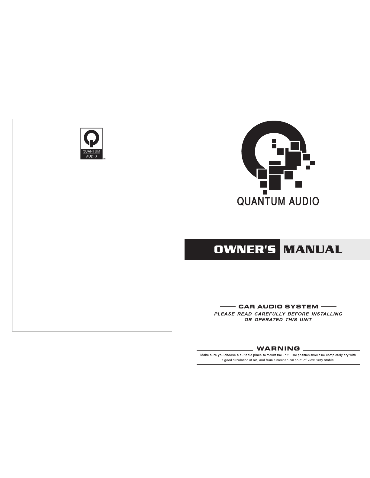
Power Connections
It is important that you read this manual very carefully and follow it for your installation carefully.
Before you start your installation,please consider following concerns.
1.Disconnect the negative (-) battery cable before mounting the amplifier or making any connections .
Check the battery and alternator ground (-) connections. Make sure they are properly connected and
free of corrosion.
2.Before selecting a mounting location for amplifier, please take some concerns into consideration
with cooling efficiency and safety.
3.Power connection
Before installing amplifier,disconnect the negative (-) wire from battery to protect any accidental
damage to your amplifier and System.This Amplifier is designed to use 8 AWG POWER and GROUND
cables.
4.Ground connection
Locate a secure grounding connection as close to the amplifier as possible. Make sure the location is
clean and provides a direct electrical connection to the frame of the vehicle.Connect one end of a
short piece of the same size cables as the power cable to the grounding point.Run the other end
of the cable to the amplifier mounting location. Connectiot the ground cable to the screw terminal
labeled as GND.
5.Remote connection
Run a remote turn on cable from the switched +12V source you will be using to turn on the system
components. This may be a toggle switch, a relay, or your source unit`s remote trigger wire, or power
antenna trigger wire. Connect the remote turn on cable to the power terminal labeled as REM. Run
this lead to the amplifier mounting location. Using 16AWG wire or larger.