Quantum TIER1-AR2 User manual

QUANTUM TIER1-AR2
Water Softener

2
Table of Contents
What’s Included..................................................................3
Operating Conditions .........................................................5
Assembly Instructions ........................................................7
Master Programming..........................................................13
Care and Maintenance........................................................17

3
What is included with the TIER1-AR2
Check the entire unit for any shipping-related damage, missing parts, or damage to shipping cartons. Contact the
transportation company for all damage and loss claims. Tier1®is not responsible for damage in transit. Small parts
needed to assemble the softener are contained in parts bags, the control valve box, or in the owner’s manual zip-lock
bag. To avoid loss of small parts, keep them in the parts bag until you are ready to use them.
What is included in the box?
Model TIER1-AR2 includes the following:
1. Control Valve with Bypass
2. Resin Tank
3. Parts Bags
4. Owner’s Manual Zip-lock Bag
5. Brine Tank and Brine Valve Assembly
1. Control Valve
Upper
Distributor
5. Brine Tank
3. Parts Bags
2. Resin Tank
4. Owner’s Manual Resealable Bag
Distributor
Tube Inside
of Tank
Parts Bag A includes:
1. Brine Well Overow Elbow
2. Brine Well Bracket
3. Blue “C” Clip
Parts Bag B includes:
1. Master O-Ring (3.25” outside diameter)
2. Brine Line Connector Nut
3. Brine Line Bushing/Filter Screen
1. Owner’s Manual
2. Hose clamps (x2)
3. Silicone Lubricant
A. Control Valve
B. Bypass and 4 clips
C. Clear Drain Tubing (10’)
D. PVC Tubing
E. Upper Distributor
F. Brine Valve
G. Brine Well
H. Control Valve Power Cord
Additional Components
1 2 3
1 2 3
A DC E F GB H

4
Operating Conditions
This softening system will operate at maximum efciency under the following conditions:
Operating Conditions
Working conditions Working pressure 21 psi to 120 psi
Water temperature 40°F - 120°F (5° C - 50°C)
Working Environment
Environment temperature 40°F - 120°F (5°C - 50°C)
Relative humidity ≤95% when temperature is 25C/77°F
Power source AC100~240V/50~60Hz
Inlet Water Quality
Water turbidity Down-ow Regeneration <5FTU
Chlorine <0.1ppm
Iron2 <0.3ppm
• All plumbing and electrical work should be performed by an accredited professional to ensure all local, munici-
pal, and state codes are met.
• Do not use the water softener with water that is unsafe or of unknown quality.
• Do not use the brine tube, injector body, or other connectors on the valve as a handle to carry the system.
•Ensure there is salt in the brine tank at all times when in use for softening. The brine tank should contain clean
water softening salt only, at least 99.5% pure. Do not use small grain salt.
•When there is moderate to high turbidity, a lter should be installed before the softening system on the inlet
side.
• If the water pressure exceeds 80 psi, it is recommended to install a pressure valve. If the water pressure is under
20 psi, a boost pump must be installed before the water inlet.

5
Assembly Instructions
Locate the following parts:
Brine Tank - Inside the brine tank you will nd:
A. Control Valve with
B. Bypass with 4 clips
C. Clear Drain Tubing (10’)
D. PVC Tubing
E. Upper Distributor
F. Brine Valve
G. Brine Well
H. Control Valve Power Cord
Parts Bag A includes:
1. Brine Well Overow Elbow
2. Brine Well Bracket
3. Blue “C” Clip
1 2 3
Parts Bag B includes:
1. Master O-Ring (3.25” outside diameter)
2. Brine Line Nut
3. Brine Line Bushing/Filter Screen
4. Owner’s Manual Resealable Bag
1. Owner’s Manual
2. Hose clamps (x2)
3. Silicone Lubricant
A DC E F GB
1 2 3
H

6
Prior to Assembly
IMPORTANT NOTE: To avoid irreversible
damage to connector threading, hand tighten
plastic connections rst. If leaks are noted
during initial start up, gently tighten with tool.
1. Prior to installation of this water softener, ensure you are aware of local laws and
codes regarding the installation, use, and maintenance of water softeners.
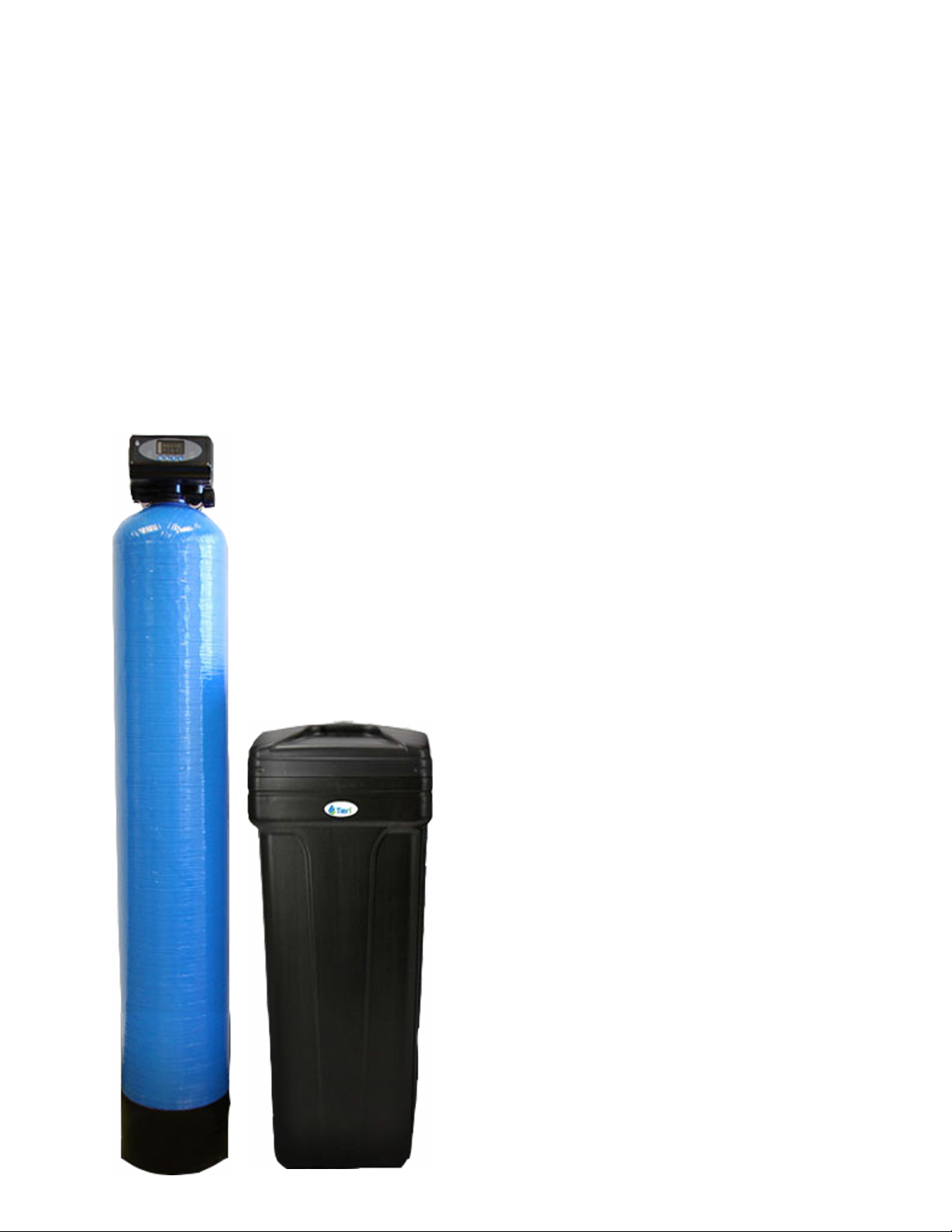
2. Resin Tank - the tank may be shipped with a temporary shipping cap, a master
O-Ring, and a piece of tape covering the riser tube. This is to prevent resin from
entering the riser tube during shipping. The cap, master O-Ring, and tape must
be removed and discarded prior to attaching control valve and the upper distrib-
utor. (Another master O-ring is supplied.)
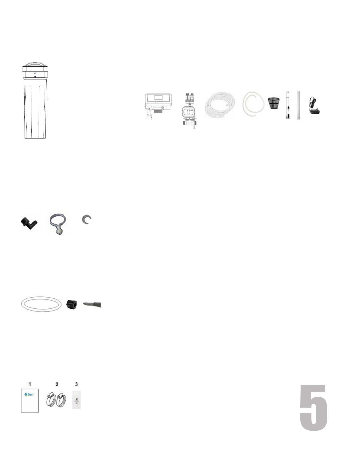
3. Unpack the product and ensure all listed parts are included.
4. Turn off the main water line to your home prior to installation.
5. If you will be draining the tank, shut offthe power supply to your water heater.
6. Turn on the water faucets in the highest and lowest levels of your home.
Begin assembly on pages 7-12.

7
Assembly Instructions
STEP 1: Attach the Control Valve to the Resin Tank
A. Locate the Master O-ring (from Parts Bag B) and lightly coat with silicone lubricant (from Owner’s Manual Zip-
lock Bag). Insert into bottom of control valve as shown below.
B. Connect the upper distributor to bottom of control valve, line up slots and twist as shown below.
C. Center the riser pipe within the resin tank.
D. Attach the control valve to the resin tank by sliding the upper distributor over the riser pipe.
E. Securely tighten the control valve by hand, tightening it clockwise.
Twist to securely seat

8
Assembly Instructions
STEP 2: Connect Bypass Valve to Control Valve
A. Attach bypass valve to control valve by rmly pushing inlet and outlet of bypass valve into control valve. Install
plastic clips to secure bypass.
B. Connect inlet and outlet elbow connectors to pipe connection end of bypass valve. Install plastic clips.
C. Connect the signal wire ends from control valve and bypass. Tighten nut.
D. Verify water meter probe is installed in probe port on control valve.
Top view of bypass assembly
Outlet
Inlet Clip
Signal wire Outlet elbow
connector
Inlet elbow
connector
Water meter
probe

9
Assembly Instructions
STEP 3: Connect Brine Line to the Brine Tank
A. Remove brine well cap from brine well.
C. Remove nut from threaded end of brine well bracket. Slide
bracket (1) over top of brine well, lining up hole in bracket with
hole in brine tank as shown in Figure 1.1.
D. Insert threaded end of bracket into top hole (2) of brine tank.
Replace nut on bracket outside of hole in tank.
E. Feed PVC tubing (3) from outside the brine tank through the
hole in the bracket. Push tubing rmly into quick connect tting
on brine valve.
F. When fully inserted, secure tubing by placing blue “c” clamp (4)
from Parts Bag A in between collar of quick connect tting and
brine valve.
G. Replace brine well cap.
Brine well bracket Blue “C” clamp
Threaded Nut
FIGURE 1.1
B. Locate brine well bracket and blue “C” clamp in Parts Bag A.
Follow steps on next page to connect brine tubing to control valve.

10
Assembly Instructions
A. Slide brine nut over end of brine tube. Insert brine tube bushing/lter screen into the end of brine tube.
B. Insert brine tubing into brine line connector.
C. Tighten hexagonal nut onto brine line connector.
STEP 4: Connect Brine Line to the Control Valve
STEP 5: Connect backwash drain line to control valve
A. Slide drain hose connector into drain outlet.
B. Insert drain line ow control into drain outlet.
C. Attach clear drain tubing to connector. Secure
using a hose clamp (from Owner’s Manual Zip-
lock Bag.)
D. Secure the clear drain tubing over a oor drain
or other suitable drain. Leave an air gap of
about 1 1/2” between the end of the hose and
the drain. An air gap is necessary to prevent
backow of sewer line.
Drain Outlet
Drain line
ow control
Clear drain tubing
Clip
Drain hose
connector
Note: There is one 10’ length of clear drain tubing provided. This tubing will need to be cut to be used for both
backwash drain line from control valve and overow drain line from brine tank. You should measure the length you
need for the backwash line from the resin tank rst, using the remainder for the brine tank overow line.
Air gap to drain
Brine tube
Brine Nut
Bushing/Filter Screen
Brine line connector
Brine line ow control
O-ring
Clip

11
Assembly Instructions
Inlet elbow
connector
Outlet elbow
connector
Signal wire
Power Cord
Plug
Power
Cord Plug
Brine line
connector
Bypass
Drain connector
STEP 6: Connect overow drain line to brine tank
A. Locate overow elbow (in Parts Bag A.) Remove nut from
threading. Insert drain elbow (1) in bottom half of brine
tank below brine line as shown in Figure 1.2.
B. Replace nut on drain elbow inside of brine tank. Attach
clear drain tubing (2) to the drain elbow. Secure with hose
clamp (form Owner’s Manual Zip-Lock Bag).
C. Secure the clear drain tubing over a oor drain or other
suitable drain. Check your local codes to ensure compliance.
Leave an air gap of about 1 1/2” between the end of the
hose and the drain. An air gap is necessary to prevent
backow of sewer line.
Overow
elbow
Hose
clamp
FIGURE 1.2
1
2
STEP 7: Connect Inlet elbow connector to home water supply.
STEP 8: Connect Outlet elbow connector to home plumbing.
STEP 9: Flush water lines and program control valve as on following pages before rst use.

12
Flushing the water lines
Before operating water softener for the rst time, ush out your water lines and the water softener bypass.
System Startup and Programming
Attach one plug of the power cord to the control valve power cord (top cord), and the other plug to the bypass
power cord. Plug in the power cord.
Programming instructions begin on next page.
A programming key detailing button settings is below.
Step by step programming instructions begin on page 13.
Please review all settings and adjust as necessary for your water hardness to ensure that the water softener will work
most effectively for your needs.
Display Screen
UpDownBack/Regen
Menu/Conrm Button Area
12:12
1. Turn off the water source at the inlet to your home.
2. Disconnect the bypass from the control valve.
3. Place a container underneath the bypass to catch water. Turn on the water source to allow water to ow through
and remove any foreign material from the water lines.
4. Turn off the water source.
5. Reconnect the bypass to the control valve.
6. Check for any leaks.

13
Programming
Valve Programming Instructions
When control valve is rst plugged in, screen will show “F79”. After a minute, a beep will sound and the button
lock indicator- - will display. The default time of day - 12:12 - will ash in the middle of the screen.
To begin programming, press and hold both up and down keys for 5 seconds until the button lock
indicator light turns off.
Item Process Steps Screen Display
Time of Day 1. Press Menu key. Display shows “Set
Soener Para.” as shown in Fig. 2A. “Set Time of
Day” is selected automatically.
2. Press Menu key. Display shows “Set Time of Day”
as in Fig. 2B. (24-hour clock.) Hour value “12”
ashes. Press Up or Down keys to adjust hour value.
3. Press Menu key. Minute value “30” ashes. Press
Up or Down keys to adjust Minute value.
4. Press Menu key to return to rst screen.
Regeneration
Time
1. Press Down key to select “Set Regen. Time” as in
Fig. 2-C.
2. Press Menu key. Display shows “Set Regen. Time”
as shown in Fig. 2D. Hour value “02” ashes. Press
Up or Down key to adjust hour value.
3. Press Menu key. Minute value “00” ashes. Press
Up or Down key to adjust minute value.
4. Press Menu key to return to rst screen.
Water
Hardness
1. Press Down key to select “Set Water Hardness” as
in Fig. 2E.
2. Press Menu key. Displays shows “Set Water
Hardness” as shown in Fig. 2F. Hardness value
“150” ashes. Press Up or Down to adjust hardness
value in mg/l [mg/l = parts per million (ppm)]
3. Press Menu key to return to rst screen.
Bypass Set 1. Press Down key to select “Bypass set” as in Fig.
2G.
2. Press Menu key. Display shows “Bypass set” as in
Fig. 2H. Press Up or Down key to choose Intelligent
Bypass mode.
3.Press Menu key to return to select mode.
4. Press Regen key to return to home screen
and put soener into service.
Set Soener Para.
Set Time of Day
Set Regen. Time
Set Water Hardness
Set Time of Day
12:30
Set Soener Para.
Set Time of Day
Set Regen. Time
Set Water Hardness
Set Regen. Time
02:00
Set Soener Para.
Set Time of Day
Set Regen. Time
Set Water Hardness
Set Water Hardness
150 mg/L
Set Soener Para.
Set Regen. Time
Set Water Hardness
Bypass Set
Bypass set
Intelligent bypass
No bypass
Fully bypass
Fig. 2A
Fig. 2B
Fig. 2C
Fig. 2D
Fig. 2E
Fig. 2F
Fig. 2G
Fig. 2H

14
Programming
12:12:00
Water System
In-Service
Water
Cur. F.R.:
0.00 gpm
12:12:00
Water System
In-Service
Water
Regen. Time:
02:00
12:12:00
Water System
In-Service
Water
Remaining
3698 gal
Control Valve Display while in Service
While in service, the control valve rotates between the following screens:
12:12:00
Water System
In-Service
Bypassing Stage III
Screen 1:
Button lock key Current time of day in 24-hour clock
Number of gallons remaining to be used before triggering a regeneration.
Note: Typical water usage is calculated at 75 gallons per person per day.
Screen 2:
Button lock key Current time of day in 24-hour clock
Current water ow rate in gallons per minute. When a faucet is turned on
this should register a number if everything is working correctly.
Screen3:
Button lock key Current time of day in 24-hour clock
Regeneration Time of Day (default setting is 2:00 AM)
Screen 4:
Button lock key Current time of day in 24-hour clock
Automatic bypass setting based on water hardness. Stage I: 426 - 550 mg/L
Stage II: 301-425 mg/L Stage III: 200-300 mg/L

15
Programming
After Control Valve has been programmed, perform the following steps before rst use:
Open a water line and let water ow until water runs clear.
Press and hold both up and down keys simultaneously for 3 seconds to unlock the key pad.
Press Regen key to advance through each cycle, following the below instructions.
When you press the Regen key, the screen will display “motor running” as it positions the ceramic disc. Once
“motor running” disappears and the next phase is displayed, press manual return key to advance to the next phrase.
1 - Backwash - lets air out of the drain line. Process will take 8-10 minutes to purge the system.
Press Regen key to advance to the next phase, brine and slow rinse.
2 - Brine and slow rinse - verify the air check valve is closed by listening to be sure no air is being drawn into the
system. Press Regen key to advance to the next phase, brine rell.
3 - Brine rell - This stage will ll the brine tank with the correct amount of water. Allow the brine rell phase to
run, do not advance past this phase until it is complete. After this phase has completed, press Regen key to advance
to Fast rinse, then press Regen key again to return to In Service position.
Add salt to the brine tank (40 pound minimum, 120 pound maximum).
Note: We recommend using water softener salt, 99% pure.
Install brine tank cover.
Turn on a faucet away from the installation location. Turn off faucet when plumbing lines have been purged.
Your water softener should now be fully operational.
To verify that your water softener is functioning correctly, take a water sample test to verify hardness reduction.
Manual Regeneration
To force a manual regeneration:
Press and hold up and down keys for ve seconds until a beep sounds and the button lock indicator light
turns off.
Press Regen key to start the backwash.
Press Regen key again to move to Brine and Slow Rinse (60 minutes)
Press Regen key again to move to Brine Rell (13 minutes)
Press Regen key again to move to Fast rinse (10 minutes)
Press Regen key again to return to In-Service.

16
Bypass Valve Information
Automatic Bypass Information
The automatic bypass is controlled by the settings
chosen on the control valve.
The keys on the bypass valve serve no function when
connected to the control valve and should not be used.
Bypass stages
The bypass stage used by the automatic bypass is
determined by the water hardness setting selected during
programming of the control valve.
Bypassing Stage III - water hardness 200-300 mg/L
Bypassing Stage II - water hardness 301-425 mg/L
Bypassing Stage I - water hardness 426-550 mg/L
Turning O Bypass
The control valve controls the bypass settings. To change the bypass settings, press and hold both up and
down keys simultaneously for 3 seconds to unlock the key pad.
Press Menu key. Display shows “Set Soener Para.”
“Set Time of Day” is selected automatically.
Press Down key until can select “Bypass set” as shown in Fig. 3A.
Bypass is set to Intelligent Bypass during normal service as shown in Fig. 3B.
If you do not want unsoftened water to be able to ow during your
softener’s regeneration, press Down key to select “No bypass”.
If you want to allow water to fully bypass the water softener, press Down key to
select “Fully Bypass.”
Press Menu key to return to In-Service Status.
Set Soener Para.
Set Regen. Time
Set Water Hardness
Bypass Set
Bypass set
Intelligent bypass
No bypass
Fully bypass
Fig. 3A
Fig. 3B
Top view of bypass assembly

17
Care and Maintenance
Bridging
Humidity or the wrong type of salt may create a cavity between the water and the salt. This action, known as
“bridging”, prevents the brine solution from being made, preventing the water softener from working.
If you suspect salt bridging, carefully pound on the outside ofthe plastic brine tank, or pour some warm water over
the salt to break up the bridge. This should always be followed by allowing the unit to use up any remaining salt, and
then thoroughly cleaning out the brine tank. Allow four hours to produce a brine solution, then manually regenerate
the softener.
Caution
Liquid brine will irritate eyes, skin, and open wounds. Gently wash exposed areas with fresh water. Keep children
away from water softener.
Product Care
To retain the attractive appearance of your new softener, clean occasionally with a mild soap solution. Do not
use abrasive cleaners, ammonia, or solvents. Never subject your softener to freezing or to temperatures above 43
degrees Celsius (110 degrees Fahrenheit).
Effective water softener maintenance is critical to ensuring your system operates efciently. The Tier1 water
softener cleanser is packaged in a 16 ounce bottle, simply pour the entire bottle into the brine well every four
months. The cleanser will eliminate contaminants and build up that are not removed during a backwash cycle or
regeneration phase.

TIER1-AR2
Water Softener
SOMETHING NOT RIGHT?
Our Support Team is here to assist you. We’re
happy to answer any questions you may have.
Quality Water Treatment
Quantum Authorized Dealer
866-278-4130
www.QualityWaterTreatment.com
Version 1.15.21
Table of contents
Other Quantum Water Dispenser manuals
Popular Water Dispenser manuals by other brands

BWT
BWT AQA Perla Installation and operating manual

Kenmore
Kenmore SOFTENERS-275-280 owner's manual

BWT
BWT INTEGRAL Assembly, Commissioning, Operation and Maintenance Manual

Verbatim
Verbatim CP005E user manual

SPT
SPT SP-3618 instruction manual

3M
3M Aqua-Pure CS Series Installation and operating instructions

resideo
resideo Braukmann KaltecSoft KS10S installation instructions

Hatco
Hatco ATMOSPHERIC AWD-12 Series Installation and operating manual

GE
GE Profile FQROMF Instruction manual and performance data sheet

Elkay
Elkay EWA14 2JO Series Installation, care & use manual

Crown
Crown CWD-1925 Pure quick start guide

Soleus Air
Soleus Air WA2-02-50A user manual