Quanzhou 9900 User manual

1
Operation Instructions of 9900
Vehicle-Mounted Walkie Talkie
©All rights reserved Quanzhou Baojie Electronics Co., Ltd.

2
致谢
感谢讲机亦不例外。本公司相信本产品将同时满足您对语音和资料通讯的苛刻要求。
Acknowledgement
Thank you for purchasing this walkie talkie. We have been dedicated to providing novel and fine
radio products, including this walkie talkie. We believe this product will satisfy your strict
requirements on both voice and data communication.
Important Notice:
Attentions
Please observe the following instructions to avoid fire, human injure or device damage.
Do not try to set the walkie talkie during driving, which may lead to dangerous consequence.
Do not transmit at a large power for a long time. Otherwise, the walkie talkie may become
too hot so that its service life will be shortened.
Unless otherwise specified in this manual or instructions, do not dismantle or retrofit the
walkie talkie for any reason.
Explosive atmosphere (gas, dust, smog, etc.)
Please turn off the walkie talkie in oil filling or when your vehicle stops at a filling
station. If your walkie talkie is installed in the trunk, please not place the reserve fuel
tank in the trunk.
Damage from radio signal transmission
When there is any person around the antenna fittings or touching the antenna, please
do not operate your walkie talkie so as to avoid possible damage or human body
injure due to radio frequency.
Gunpowder and detonator
The operation of the talkie walkie within 150m (500ft) to gunpowder and detonator
may lead to explosion. In the region of explosion or the region with sign “Close
dual-way radio”, please turn off your walkie talkie. If your vehicle is used to
transport gunpowder and detonator, be sure they are in the black sealed metal box
with internal packing layer. Do not transmit signals when you put the gunpowder and
detonator into or take out them from the metal box.
金属箱内运输。将火药、雷管放入或从包装箱中取出时,不要发射讯号。
Warning
Friendly Reminder:
The purchase and use of this device is an acts of setting up and using a radio station, and must
go through the procedures by laws for the approval of radio station setup and obtain a license
for radio station. The use of this device shall conform to the items approved by the license
thereof. Any radio station or radio interference business without authorization, any operation
thereof exceeding the scope of license and other acts violating the radio administration
regulations shall be punished by the radio administrative institution. Serous conducts may
violate Article 288 of the Criminal Law or Article 28 of the Public Security Administration
Punishment Law, and a criminal punishment of fixed term imprisonment of not more than
three years, criminal detention or public surveillance and additional or exclusive fine or
administration punishment of detention by public security organ may be imposed.

3
Do not expose the walkie talkie to blazing sun for quite a long time or put it near a heating
appliance.
Do not put the walkie talkie at places where there is too much dust, damp or water splash or
on instable surface.
If any abnormal smell or fume is found from the walkie talkie, immediately turn off its power
and contact the local distributer.
Using a walkie talkie in driving may violate traffic laws. Please inquire or consult the local
transportation administration body about it and observe the local traffic laws.
Do not use options not designated by this company.
The walkie talkie is designed to use 13.8V DC (±15%) power supply! Never use 24V
batteries. Prior to installing it on the vehicle, please inspect the battery polarity and
voltage of the vehicle.
Only use the DC power line attached or designated by this company.
Never insert a metal object into the cooling fan.
Attention
Do not cut down or remove the fuse holder of the DC wire. Wrong connection may
lead to fume and further fire.
To ensure passengers’ safety, please use the attached installation support and screw
set in the installation of the walkie talkie and be sure that it will not slip out in case of
vehicle collision.
Lack of proper protection or isolation of various electronic devices in the vehicle
from radio RF energy during the transmission of the walkie talkie may lead to their
damage. For example, electronic fuel injector, anti-slide brake and navigation control
system are easy to be damaged. If your vehicle is furnished with such devices, please
consult the vehicle distributor on whether it is necessary to protect them in
transmission.
Warning

4
Table of Contents
Preparation
Standard Configuration Accessories---------------------------------------------------------------------6
Installation of Walkie Talkie------------------------------------------------------------------------------6
Power Line Connection -----------------------------------------------------------------------------------6
Connection of Antenna------------------------------------------------------------------------------------8
Removal and Installation of Front Panel----------------------------------------------------------------8
Connection of Accessories--------------------------------------------------------------------------------9
Get Familiar with the Talkie Walkie
Front Panel------------------------------------------------------------------------------------------------10
Display ----------------------------------------------------------------------------------------------------12
Screen------------------------------------------------------------------------------------------------------12
Rear Panel-------------------------------------------------------------------------------------------------13
Subpanel---------------------------------------------------------------------------------------------------13
Handheld Microphone-----------------------------------------------------------------------------------14
Basic Operations
Turn On/Off the Talkie Walkie-----------------------------------------------------------------------15
VolumeAdjustment------------------------------------------------------------------------------------15
Squelch Level Adjustment----------------------------------------------------------------------------15
Selection of Frequency Band-------------------------------------------------------------------------15
Selection of Operation Mode-------------------------------------------------------------------------16
Transmission--------------------------------------------------------------------------------------------17
Selection of Transmission Power---------------------------------------------------------------------17
Context Menu Mode
Setting of Context Menus-----------------------------------------------------------------------------19
Context Menu Setting----------------------------------------------------------------------------------19
Operation via Repeater
Setting of Repeater------------------------------------------------------------------------------------21
Selection of Pilot Frequency-------------------------------------------------------------------------23
Transmission of Pilot Frequency--------------------------------------------------------------------23
Reverse Frequency Function------------------------------------------------------------------------23
Memory Channel
Memory Channels for Simplex Transmission/Receiving with the Identical Frequency or
Transmission /Receiving with Different Frequencies? -----------------------------------------24
Storage of the Same Frequency for Simplex and Standard Transmission/Receiving in
Memory Channel-------------------------------------------------------------------------------------25
Storage of Different Frequencies of Transmission /Receiving in Memory
Channel------------------------------------------------------------------------------------------------25
批注 [u1]: 目录中的标红处的标题与
正文处不符

5
Use of Memory Channel----------------------------------------------------------------------------26
Clear of Memory Channel--------------------------------------------------------------------------26
Scanning
Scanning Mode---------------------------------------------------------------------------------------27
Turn on Scanning------------------------------------------------------------------------------------27
Continuous Tone Coded Squelch System (CTCSS)
Use of CTCSS------------------------------------------------------------------------------------------27
Digital Coded Squelch (DCS)
Use of DCS--------------------------------------------------------------------------------------------28
Dual Tone Multiple Frequency (DTMF)
Setting of DTMF code block--------------------------------------------------------------------------30
Selection of receiving DTMF code block------------------------------------------------------------31
Selection of squelch mode-----------------------------------------------------------------------------32
Selection of transmission of DTMF code block-----------------------------------------------------32
Selection of DTMF transmission mode---------------------------------------------------------------33
Selection of DTMF transmission time----------------------------------------------------------------34
FM Radio
Use of FM radio-----------------------------------------------------------------------------------------35
Auxiliary Functions
Power-on Information---------------------------------------------------------------------------------35
Key Locking--------------------------------------------------------------------------------------------35
Setting of Wide and Narrow Bands (W/NA)-------------------------------------------------------35
Setting of Voice Companding (COMP)-------------------------------------------------------------36
Setting of Voice Encryption (SRMR)---------------------------------------------------------------37
Setting of Frequency Step (STEP)-------------------------------------------------------------------37
Setting of Prompt Tone (BEEP)----------------------------------------------------------------------38
Setting of Backlight (LED)---------------------------------------------------------------------------38
Setting of Busy Channel Lock (BCL)---------------------------------------------------------------38
Setting of Transmission Time-out Timer (TOT)---------------------------------------------------39
Restoration of Factory Setting (RESET)------------------------------------------------------------40
Operation of AM Aircraft Frequency Band
Setting Steps for AM Aircraft Frequency Band----------------------------------------------------41
Operation of Cross-Band Repeater
Setting Steps for Cross-Band Repeater Operation-------------------------------------------------42
Maintenance
General Information-----------------------------------------------------------------------------------43
Repair----------------------------------------------------------------------------------------------------43
Clean-up-------------------------------------------------------------------------------------------------43

6
Troubleshooting----------------------------------------------------------------------------------------43
Technical Parameters
Annex 1: Continuous Tone Coded Squelch System (CTCSS)----------------------------------44
Annex 2: Digital Coded Squelch (DCS)-----------------------------------------------------------44
Specifications------------------------------------------------------------------------------------------45
Declaration---------------------------------------------------------------------------------45
Standard Configuration Accessories
Handheld microphone
Holder for handheld microphone
DC power line
Installation support
Screw set
Fuse
Operation Instructions
Installation of Walkie Talkie
Select a safe and convenient site in your vehicle so as to reduce possible damage to your
passenger or yourself during vehicle movement. You may install the walkie talkie blow the
instrument panel in front of the front passenger seats so that your knee and legs will not collide the
walkie talkie. It’s best to select a well ventilated site where direct exposure to sun can be avoided.
1. Use the attached self-tapping screws (4) and flat washers (4) to install the installation support in
the vehicle as shown in Fig. 1 and Fig. 2.
Fig. 1 Fig.2 Fig. 3
2. Fix the walkie talkie, and then insert and tighten the attached the (4) hexagonal screws as shown
in Fig. 3.
Make sure all screws are tightened to avoid loosening of the support or the walkie talkie in
vibration of vehicle.
Utilize the 3 screw grooves at the side rear side of each support to install the main body at a
proper inclined angle as shown in Fig., 4, 5 and 6.
Fig. 4 Fig. 5 Fig. 6
Power Line Connection
Operation of talkie walkie
Be sure to use 12V vehicle batteries with sufficient electricity. If the electricity is insufficient,
the display screen will turn dark or the transmission output power may greatly decrease during the
transmission. Never connect the talkie walkie to 24V batteries.
Note: If you use the talkie walkie when the vehicle-use batteries are not sufficiently
charged or the generator is off, battery discharge may lead to insufficient electricity quantity,
making it difficult to start the vehicle. Therefore, try to avoid use the talkie walkie in such
situation.
1. Use the DC power line attached with the talkie walkie to connect the talkie walkie with the
Vehicle body
Installation support
Cone screw
Washer M5

7
vehicle battery terminal in a shortest route.
It is suggested not to use a cigar lighter socket as much as possible as some of them
may lead to great voltage drop.
The whole power line must be packed so as to isolate it from heat and moisture and
from the generator ignition system/connection line.
2. When the power line is installed in place, wind the fuse holder with heat-resistant adhesive
tape to protect it against moisture. It’s better to use heat-resistant adhesive tape to wrap the
whole power line.
3. To prevent short-circuit, disconnect the other connection lines at the negative (-) battery
terminal before connecting the talkie walkie.
4. Please first confirm the polarity of connection is correct, and then connect the power line
to the battery terminal. Connect the red wire to the positive (+) terminal of battery and the
black wire to the negative (-) terminal of battery.
Use the whole power line and do not cut the surplus part even if it is longer than
required. Be sure to remember: never remove the fuse holder from the power line.
5. Reconnect all connection lines that have been disconnected from the negative terminal
previously.
6. Connect the DC power line to the walkie talkie.
Press them together with force till the locating plate is locked with a sound of
“click”.
Operation of fixed radio station
If you intend to use the talkie walkie as a fixed radio station, you need to buy a independent
type of 13.8 DC power supply separately with a suggested continuous current capacity of
above 12A.
Note:
Do not connect this DC power supply to the AC power socket before all connections are
completed. (Do not connect the talkie walkie with power on.)
Please connect all lines and finally insert the DC power supply device into the AC
socket.
1. Be sure the talkie walkie and the DC power supply are off.
2. Connect the DC power supply line to the DC regulated power supply and make sure the
polarities are correct (red: positive, black: negative).
Never directly connect the talkie walkie to theAC socket.
Use the DC power line attached to connect the talkie walkie to the DC regulated
power supply.
Never use a power line with the specification and parameters lower than the
original one to replace the original power line.
3. Connect the DC power line to the talkie walkie.
Press them together with force till the locating plate is locked with a sound of
“click”.
Fuse replacement
If the fuse burns out, please find out the cause and remove it. After that, replace the fuse. If
the fuse newly installed continues to burn out, disconnect the power line and contact the
authorized distributor for help.
Red
Black

8
Location of fuse
Rated current of fuse
talkie walkie
15A
Attached DC power line
20A
Use the fuse of designated type and rated value. Otherwise, the talkie walkie may be
damaged at your own risk.
Connection of Antenna
Before using the talkie walkie, you must install a high efficiency and fine tuned antenna.
Successful installation depends on the correct antenna type and installation. If a proper
antenna system is selected and installed correctly, the talkie walkie will achieve best
performance.
Use an antenna with a characteristic impedance of 50Ω and a low loss coaxial feeder
also with 50Ω characteristic impedance to match the input impedance of the talkie walkie.
Using a feeder with an impedance of other than 50Ω to connect the antenna with the talkie
walkie will reduce the performance of the antenna system, may cause interference to the
nearby radio and TV receivers, radio receivers and other electronic devices and even damage
the talkie walkie.
Without the connection with antenna or other matched load, it is prohibited to use
the talkie walkie to transmit. Otherwise, the talkie walkie will be damaged. Be sure
to connect the antenna to the talkie walkie before transmission, and only when the
connection is confirmed can the transmission be made.
All fixed radio stations must be furnished with a lightning arrester to reduce the
risk of the damage of talkie walkie by fire or electric shock.
The location and fixed mode of the antenna on the vehicle are shown as follows:
Removal and Installation of Front Panel
In the light of the location/mode of the installation of talkie walkie, you may remove the front
panel and install it to a proper site with the extension line.
1. At the left side of the front panel, push the release bolts of the front panel directly to the
left rear direction as shown in Fig. 8.
Fig. 8
2. Slide the front panel in parallel to left and pull it out forward and away from the main body
of the talkie walkie as shown in Fig. 9.
Attention
Attention
Att

9
Fig. 9
3. Move the front panel translationally from left to right till the front panel fits the body and a
“click”is heard. Thus, the front panel is installed.
Connection of Accessories
Handheld microphone
For voice communication, connect the handheld microphone attached to the MIC socket on
the right side of the talkie walkie. Please align the RJ12 plastic spring piece upward with the
MIC socket till the locking-locating plate is locked in place with a sound of “click” as shown
in Fig. 10.
Fig.10
Get Familiar with the Talkie Walkie
Front Panel
①Left tuning knob (DIAL)
MIC socket
Plug of handheld microphone

10
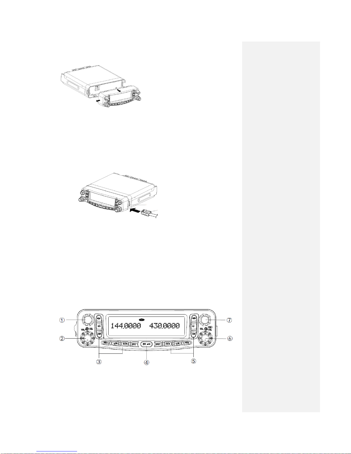
Rotate this knob to select the left band operation frequency or memory channel, change the
scanning direction and select functional menu and parameters.
Press this knob shortly to switch the left band as the main band.
If the left band is set as the main band, press this knob shortly will enter the first level and
second level of the setting status of functional menu.
In the functional menu setting status, press this knob shortly to confirm the setting.
②Left volume/muting knob (VOL SQL)
The center VOL (volume) control knob is used to tune the speaker volume in receiving by
left band. Turn it clockwise to increase the volume.
The outer SQL (squelch) control knob is used to eliminate the background noise in
receiving by left band. Turn it clockwise to the extent that the noise just disappears (the
on the screen disappears) so as to improve the sensitivity of weak signal.
③Left keys
【REV】for frequency reverse selection
Shortly press 【REV】. If the left band starts the frequency reverse function, the
transmission-receiving frequency will reverse.
【H/L】for power adjustment
Shortly press【H/L】,the left band transmission power can be switched between high power
(High) and low power (Low).
【CMP】for starting companding
Shortly press 【CMP】to open the left band companding function.
【MHz】for MHz and Mb adjustment
Shortly press【MHz】and the Mb will flicker. Turn DIAL to adjust the Mb frequency and
press DIAL shortly to confirm it.
【V/M】for switching between VFO frequency mode and memory channel mode
Shortly press this key to switch the left band frequency control mode between VFO
frequency mode and memory channel mode.
【SCN】for scanning
Shortly press this key to activate the scanning of left band.
【EXIT】for return/exit
④【FM/ 】for starting radio receiver/locking keypad
Shortly press this key to enter/exit the FM receiver mode.
Press this key for long to start the keypad lock.
⑤Right side keys
【EXIT】for return/exit
【SCN】for scanning
Shortly press this key to activate the scanning of left band.
【V/M】for switching between VFO frequency mode and memory channel mode
Shortly press this key to switch the right band frequency control mode between VFO
frequency mode and memory channel mode.
【MHz】for MHz and Mb adjustment
Shortly press【MHz】and the Mb will flicker. Turn DIAL to adjust the Mb frequency and
press DIAL shortly to confirm it.
【CMP】for starting companding
Shortly press 【CMP】to open the right band companding function
【H/L】for power adjustment
Shortly press 【H/L】and the right band transmission power can be switched between high
power (High) and low power (Low).
【REV】for frequency reverse selection
Shortly press 【REV】. If the right band starts the frequency reverse function, the
transmission-receiving frequency will reverse.
⑥Right volume/muting knob (VOL SQL)
The center VOL (volume) control knob is used to tune the speaker volume in receiving by
right band. Turn it clockwise to increase the volume.
The outer SQL (squelch) control knob is used to eliminate the background noise in
批注 [微软用户2]: 短按此键激活左
段扫描
不是右段吗?

11
receiving by right band. Turn it clockwise to the extent that the noise just disappears (the
on the screen disappears) so as to improve the sensitivity of weak signal.
⑦Right tuning knob (DIAL)
Rotate this knob to select the right band operation frequency or memory channel, change
the scanning direction and select functional menu and parameters.
Press this knob shortly to switch the right band as the main band.
If the right band is set as the main band, press this knob shortly will enter the first level and
second level of the setting status of functional menu.
In the functional menu setting status, press this knob shortly to confirm the setting.

12
Display Screen
<Left Frequency Band> <Right Frequency Band>
Icon
Description
Displays the number of memory channel and context menu.
Appears when the frequency reverse function is enabled.
No definition for this device
Appears when the transmission difference frequency offset is set as
negative.
Appears when the transmission difference frequency offset is set as
positive.
Appears when transmission of CTCSS (Continuous Tone Coded
Squelch System) is enabled in transmission status.
Appears when receiving of CTCSS (Continuous Tone Coded Squelch
System) is enabled.
Displays the transmission status.
Displays that the current frequency band is the main one.
Displays the operation frequency, name of memory channel and context
menu.
Appears in busy signal receiving
Displays the signal strength in receiving while displaying the power
level selected in transmission.
Appears when the scrambling function is on.
Appears when the companding function is on.
Appears in narrow band mode.
Appears when the DCS function is on. (When the transmission DCS is
started, it will appear only in the transmission status.)
Appears when the AM aircraft frequency band is started and the left or
right band frequency is in the scope of aircraft frequency band.
No definition for this device
Appears when low transmission power is used. (No icon display for
high transmission power).
No definition for this device
Appears when the keypad is locked.
Appears when entering the function menu mode.
No definition for this device

13
Rear Panel
①Antenna interface
Connect N-connector type external antenna to this port.
②Data interface
Connect the TNS device to this interface via 6-pin mini DIN connector. (This function is
temporally unavailable and for B model talkie walkie).
③External speaker interface
If necessary, connecting with an external speaker for better sound effect. This interface can
connect with a 2-core 3.5mm audio plug. The matched load resistance is 8 ohm. When such a plug
is inserted into the interface, the internal speaker will stop.
④13.8V DC power supply interface and fuse block
It is the DC power supply interface for supplying power to the talkie walkie. Use the DC power
line attached to connect it with the above 12A DC power supply of the vehicle battery or the
base station. Make sure the red wire is connected with the positive polarity (+) and the black
wire with the negative polarity (-) of the power supply.
Subpanel
①MIC
Connect the handheld microphone to this interface.
②PANEL
When this panel needs to be installed separately from the main body, use the optional extension
line for connection to connect the panel to this interface.

14
Handheld Microphone
①Down adjustment key (【DOWN】)
Press it to make downward adjustment or decrease the main band operation frequency value,
memory channel number (changing direction in scanning) or the setting value of function
menu.
In most cases, this key can perform the same functions as the tuning knob of the main band.
②Up adjustment key (【UP】)
Use it to make upward adjustment or increase the main band operation frequency value,
memory channel number (changing direction in scanning) or the setting value of function
menu.
In most cases, this key can perform the same functions as the tuning knob of the main band.
③Transmission key (PTT)
Press this key to transmit when speaking via the handheld microphone and release it to
receive.
④Numeric keypad
In receiving status, it is used for frequency input in VFO frequency mode;
In transmission status, it is used for DTMF dialing.
⑤Key lock switch (LOCK)
Key lock switch (all keys except PTT key)
Move the switch up and the “OFF”will appear. The handheld microphone is locked.
Move the switch down and the “ON”will appear. The handheld microphone is unlocked.
⑥for lighting (LAMP)
Switch for the keypad light.
Move the switch up and the “OFF”will appear. The keypad light is off.
Move the switch down and the “ON”will appear. The keypad light is on.

15
Basic Operations
Turn On/Off the Talkie Walkie
1. To turn on the talkie walkie, press the right band (VOL) knob for 2 seconds.
When you turn on the talkie walkie, the startup information will appear on the
display screen for 2 seconds and the display screen will return to the normal display
of operation frequency.
2. To turn off the talkie walkie, once again press the right band (VOL) knob for 2
seconds.
Volume Adjustment
The left band and right band volume adjustments are separate from each other. The left volume
knob (VOL) is for adjusting the left band volume and the right (VOL) is for adjusting the right
band volume.
Clockwise turn the volume knob will increase the volume of the selected band and
counterclockwise turn it will decrease the volume.
Squelch Level Adjustment
The left band and right band squelch adjustments are also separate from each other. The left
squelch knob (SQL) is for adjusting the left band squelch level and the right (SQL) is for adjusting
the right band squelch level as shown by the arrow in the figure below.
The squelch level function is used to close the speaker volume when there is no signal. If the
squelch level is correctly set, you will hear sound only when actually receiving signals. The higher
the squelch level, the stronger the signal strength for you to hear the sound will be.
Turn the (SQL) control bottom for the selected frequency band to just eliminate or reduce the
surrounding noise.
Selection of Frequency Band
In dual-receiving operation, the main band (transmissible band) is indicated by .

16
To set the main band, just shortly press the left tuning knob (DIAL). The icon will appear
on the left of the screen, representing that the left band is the main band now. Shortly press the
right tuning knob (DIAL) to switch the right band into the main band. With your switching the
main band from left to the right, the icon will move from the left to the right as indicated
by the arrow in the above figure.
Selection of Operation Mode
Similarly, the left and the right operation modes are separate from each other. There are two
selectable operation modes: VFO frequency mode and memory channel mode.
Shortly press the left or right 【V/M】key to switch between the VFO frequency mode and
memory channel mode for the corresponding frequency band.
VFO frequency mode
1、In VFO frequency mode, you may manually change the operation frequency.
1. Rotate the tuning knob (DIAL) to tune the frequency of the current band in accordance
with the preset frequency step conveniently. Clockwise rotation will increase the frequency
and counterclockwise rotation can reduce the operation frequency.
2. You may also adjust the frequency by【UP】/【DOWN】key on the handheld microphone
or directly enter the required frequency value via its keypad.
3. To make a large amount of frequency adjustment, you may shortly press 【MHz】key to
enter the MHz mode. In the MHz mode, rotate the tuning knob to make frequency adjustment
at 1MHz interval. Shortly press the tuning knob to confirm and exit the MHz mode and use
the general frequency step to adjust the frequency.
Shortly press【EXIT】key will exit the MHz mode without storage.
Note: The product offers the frequency steps of 2.5K, 5K, 6.25K, 10K, 12.5K, 25K and 50K
for your choice.
Memory channel mode
The memory channel mode enables you to quickly select the commonly used frequencies and
related data stored in the memory of the talkie walkie.
Rotate the tuning knob (DIAL) to select the needed memory channel. Clockwise rotation
will lead to the higher frequency channel and counterclockwise rotation will lead to the lower
operation frequency channel.

17
Note: Refer to No. 24 page for the details of the setting of memory channel.
Transmission
1. Select the required frequency band and frequency/channel.
2. Press and hold the【PTT】switch of the handheld microphone and speak toward it for
transmission.
The screen will display the and RF power meter of the
selected transmission frequency band. The RF power meter displays the relative power of
the transmission output.
Speak toward the handheld microphone with normal voice and keep it 5cm from your
mouth. Too near to the microphone or too loud a voice will increase the distortion of the
signals received by the receiving radio and reduce their understandability.
3. After the completion of speaking, release the【PTT】switch.
Selection of Transmission Power
Under good communication conditions, it is better to select a lower transmission power, which
may reduce the risk of interference with the other frequencies at the same band. When a battery
power supply is used, make sure if recharging is needed to prepare for long time use.
Shortly press 【H/L】key to select high power (no display) or low ( ) power.
You may set the left and right bands with different power levels.
You may also adjust the transmission power by context menu.
1. Shortly press the tuning knob (DIAL) to enter the context menu.
2. Rotate (DIAL) to select Item 11 on the context menu.

18
3. Shortly press the tuning knob (DIAL)to set the current context menu.
4. Rotate the tuning knob (DIAL) to select “HIGH (high power) or LOW (low
power )”.
5. Shortly press the tuning knob (DIAL) to confirm the storage of the required value.
Or shortly press 【EXIT】to return to the context menu mode without storage.
6. shortly press 【EXIT】to exit the context menu mode.
Note: If the talkie walkie is too hot due to the high temperature in surrounding environment
temperature or continuous transmission, the protection circuit may automatically start the
protection function to reduce the transmission output power.

19
Context Menu Mode
Many function of this walkie talkie are selected or set via the context menu (other than actual
control bottom). When you become familiar with the context menu system, you will like them for
the various functional conveniences they provide.
Setting of Context Menus
1. Shortly press the tuning knob (DIAL) and you may set the operation of context menu.
The name and number of the context menu will appear on the screen.
2. Rotate the tuning knob (DIAL) to select the required context menu.
3. Shortly press the tuning knob (DIAL) to set the current context menu.
4. Rotate the tuning knob (DIAL) to select the required value for the selected context menu.
5. Shortly press the tuning knob (DIAL) to set the required value.
6. Repeat Steps 2~5 to set more context menus.
Shortly press 【EXIT】to cancel the setting of context menu and return to the interface
of selecting the context menu.
Once again shortly press 【EXIT】to exit the context menu mode.
Context Menu Setting
No. of
context
menu
Display
Description
Set value
Preset
Reference
page
01
R-CTCSS
Setting of CTCSS for
receiving
OFF: closed
67.0~254.1Hz
OFF
27
02
R-DCS-N
Setting of the positive code of
DCS for receiving
OFF: closed
D023N~D754N
OFF
28
03
R-DCS-I
Setting of the reverse code of
DCS for receiving
OFF: closed
D023I~D754I
OFF
29
04
R-DTMF
Setting of DTMF for
receiving
OFF: closed
DTMF1-8
OFF
31
05
SP-SQUELC
H
Squelch mode
QT: quiet talk
QT+DTMF: quiet talk
+dual tone multiple
frequency
QT
31
06
T-CTCSS
Setting of continuous tone
coded squelch system for
transmission
OFF: closed
67.0~254.1Hz
OFF
28
07
T-DCS-N
Setting of the positive code of
digital coded system DCS for
transmission
OFF: closed
D023N~D754N
OFF
29

20
08
T-DCS-I
Setting of the reverse code of
digital coded system DCS for
transmission
OFF: closed
D023I~D754I
OFF
30
09
T-DTMF
Setting of dual tone multiple
frequency for transmission
OFF: closed
DTMF1-8
OFF
32
10
PTT-ID
Transmission of ID code
OFF: closed
BOT: press to transmit the
code EOT: release to
transmit the code
BOTH: press or release to
transmit the code
OFF
33
11
POWER
Setting of transmission power
HIGH: high power
LOW: lower power
HIGH
17
12
W/NA
Selection of broad or narrow
band
WIDE: broad band
NARR: narrow band
WIDE
35
13
COMP
Voice companding
OFF : closed
ON: open
OFF
36
14
SRMR
Voice encryption
OFF :closed
ON: open
OFF
36
15
SFT
Frequency offset direction
OFF: closed
(+): positive offset
(-): negative offset
OFF
21
16
OFFSET
Frequency offset
00.0000-90.0000MHz
00.0000
22
17
STEP
Frequency step
2.50K, 5.00K, 6.25K,
10.00K, 12.50K, 25K,
50.00K
5.00K
37
18
CH-SAVE
Channel storage
128 signal channels on
either of the left and right
bands
CH-001
24
19
CH-DEL
Channel deletion
128 signal channels on
either of the left and right
bands
CH-001
26
20
BEEP
Prompt tone
OFF: closed
ON: open
ON
37
21
LED
Backlight
OFF: closed
LED1: red
LED2: blue
LED3: purple
LED4: green
LED5: yellow
LED6: light blue
LED7: white
LED4
38
22
BCL
Busy channel lock
OFF: closed
ON: open
OFF
38
23
TOT
Time out time
OFF: closed
30S~600S(20 shifts)
OFF
38
24
TONE
Pilot carrier frequency
1000Hz
1450Hz
1750Hz
2100Hz
1000HZ
23
25
DTMF-TM
DTMF transmission time
50MS
100MS
150MS
200MS
100MS
34
26
RPT
Start of cross-band repeater
OFF: closed
ON: open
OFF
42
27
AM-SW
Start of AM aircraft band
OFF: closed
ON: open
OFF
41
28
DTMF
DTMF group
8 groups
-------
30
29
RESET
Reset
RST-NO: do not reset
RES-NO
40
Table of contents