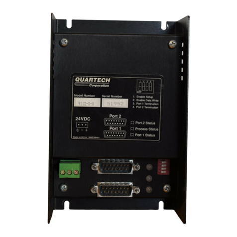
Quartech 9113-1 Series User manual

Product Manual
Model 9113-1-X
Ethernet Bridge II
for Ultra 3000 Servo
Quartech Corporation
15923 Angelo Drive
Macomb Township, Michigan 48042-4050
Phone: (586) 781-0373 FAX: (586) 781-0378
www.QuartechCorp.com
PM9113-1-X Revision 0
The product described in this document can have a variety of uses, the user and those responsible for applying this
equipment must satisfy themselves as to the acceptability of each application and the use of the unit. Under no
circumstances will QUARTECH CORPORATION be responsible or liable for any damage, including indirect or
consequential losses resulting from the use, misuse, or application of the unit.
The text, illustrations, charts, and examples included in this document are intended solely to help explain applications
of the product. Due to the many variables associated with specific uses or applications, QUARTECH
CORPORATION cannot assume responsibility or liability for actual use based upon the data provided in this
document.
No patent liability is assumed by QUARTECH CORPORATION with respect to the use of circuits, information,
equipment, or software described in this document.
This document is subject to change without notice.
PM9113-1-X Revis ion 0

Model 9113-1-X Product Manual Page 2
The Model 9113 Ethernet Bridge allows an Allen-Bradley
PLC such as a MicroLogix or CompactLogix to monitor and
control an Ultra 3000 Servo Drive over an ethernet
connection. The 9113 connects to the Ultra 3000 CN3 port
using a cable provided with the unit and to the PLC via a
10/100 auto sensing ethernet port.
The PLC will access the 9113 as though it were another PLC
using File/Element addressing. A pre-defined map exists
within the 9113 that associates Ultra 3000 Host Command
Reference parameters to File/Element numbers. The 9113
can perform scaling that allows your PLC program to work in
scaled values such as inches or RPMs.
The 9113-1-1 allows Allen Bradley Ultraware software to
access Ultra 3000 drives over an ethernet network when
used in conjunction with the Quartech Ethernet Gateway
program. The Ethernet Gateway program creates a virtual
serial port that Ultraware will connect to. Your computer
does not need to have an actual serial communication
port. The gateway uses a node address to IP address
mapping table to determine which drive to access on the
ethernet network.
Free utility suite is available that includes an IP address server, a firmware update utility, an Ultra parameter
mapping utility, and the ethernet gateway utility.. Shown below is the simplest application which does not require
an ethernet hub or switch. The PLC will access drive parameters using the Message Instruction.
9113 Web Utilities
All configuration to the 9113-1-X is accomplished by the
built in Web Utilities server accessed using your internet
browser.
The Ultra drive must have its serial communication port
configured as follows:
38400 Baud, 8 Data, No Parity, 1 Stop
PM9113-1-X Revis ion 0

Model 9113-1-X Product Manual Page 3
Theory of Operation
The 9113 allows a PLC to read and write parameters within the Ultra 3000 drive using the Message Instruction.
The parameters in the Ultra 3000 are mapped to File/Element numbers so the PLC accesses the Ultra
parameters as though they were File/Elements in a peer PLC
For the PLC to read or write File/Elements it must first establish a TCP connection to the 9113. Next the PLC
must request a session identification number from the 9113. The PLC is then ready to read and write
File/Elements as instructed by the PLC program. The TCP and session connections are transparent to the user
and PLC program but do have implications that require understanding. Once a session is established between
the 9113 and PLC it can remain indefinitely providing both devices remain wired, powered, and active.
Once a session is established the 9113 expects the PLC to make regular read/write requests. If a request is not
received for a thirty seconds then the session will be cancelled and the TCP connection will be closed. The mode
LED will be flashing green when a session is active and amber when no session is active..
When using a MicroLogix or SLC 500 Processor use the 500CPU Read and 500CPU Write commands. When
using a CompactLogic Processor use the SLC Typed Read and SLC Typed Write commands.
9113 Utility software is available free of charge at the
Quartech Corporation web site.
Also available is the latest version of this product manual
plus other related manuals and documents.
PM9113-1-X Revis ion 0

Model 9113-1-X Product Manual Page 4
Multiple Axis:
The 9113 provides a bridge to a single drive When an application requires multiple drives to be controlled then
each drive will have an associated 9113 with a unique IP address. An ethernet hub or switch will be required to
connect the devices.
Each 9113 in a network must have a unique IP address. The node address of the Ultra 3000 has no significance
in the network but must match the node set in the 9113. The 9113 is configured by the factory to access Ultra
node zero which is the default for a new Ultra 3000 drive. The node used by the 9113 can be modified using the
Web Utilities..
Address Mapping Utility
This utility will find the File/Element number associated
with an Ultra 3000 parameter you select. The utility will
run along with RSLogix and will remain on top unless
minimized. This allows you to quickly select a parameter,
copy the associated File/Element number to the
Windows clipboard then paste the number into the
RSLogix Message Instruction setup dialog.
PM9113-1-X Revis ion 0

Model 9113-1-X Product Manual Page 5
Ethernet Cables:
The 9113 operates with standard ethernet cables available from many sources. The examples below are
consistent with the TIA/EIA 568-B color code standard.
Straight Through Cable Crossover Cable
Device to Hub / Switch Device to Device
Ethernet Cable Notes:
- Straight through cables have identical color coded ends
- Crossover cables have different color coded ends.
- Straight through cables are used as a patch cord between a device and a hub or switche.
- Crossover cables are used to connect two devices directly without a hub or switch.
- Odd numbered pins are always striped, even numbered pins are always solid colored.
- The solid brown wire is always pin 8.
Serial Port Cables
The serial communication port of the 9113 uses RS-232 signal
levels. A standard six pin circular mini-DIN plug must be used on the 9113
end of all communication cables. A two foot long cable is provided with the
9113 for connection between the 9113 and Ultra 3000 serial ports.
Pin 1 - No Connection Pin 2 - Transmit Data
Pin 3 - Receive Data Pin 4 - Request-To-Send
Pin 5 - Clear-To-Send Pin 6 - Signal Common
Front view of plug
PM9113-1-X Revis ion 0

Model 9113-1-X Product Manual Page 6
2180 Cable - 9113 to Ultra 3000
(Supplied with 9113)
9 Pin Male D-Type
Ultra 3000 Communication Parameters: 38400 Baud, 8 Data Bits, No Parity, One Stop Bit
2182 Cable - 9113 to 9120 Two Port Multiplexer
9 Pin Female D-Type
Specifications:
Electrical: 24 VDC, ±5%, @ 200 ma
Temperature: 0Ec to +60Ec Operational, -20Ec to +70Ec Storage
Humidity: 10% to 95%, Non-condensing, Operational or storage
Vibration/Shock: 0.5mm displacement (X,Y,Z axis), 10-55Hz, 30G shock
Weight: approximately ½ pound
PM9113-1-X Revis ion 0

Model 9113-1-X Product Manual Page 7
9113 Hardware
Power Terminal:
Power to the 9113 is supplied through a three position removable compression terminal block. The 9113
requires 24 volt, two hundred milliamp direct current power. An earth ground connection is also required and
provided through the terminal block. Do not plug or unplug the terminal block while power is applied. Reverse
voltage and overvoltage protection are included.
Dip Switch:
Four switches are accessible through an opening at the side of the 9113 as shown in the image above. A switch
is OFF when the slider is pushed down toward the product label. Currently switches one and three are not
implemented. The operation of the 9113 is controlled by switch two and four. Do not change switch settings
while power is applied to the 9113!
If switch two and four are off...
This is the normal run mode for the 9113. The Mode LED will flash amber when no session has been initiated by
a PLC or the absence of activity by the PLC has caused a session to expire. The LED will flash green while a
session is active. Refer to the theory of operation topic for more information about sessions.
If switch four is on and switch two is on or off...
This is a mode that allows the 9113 firmware to be updated. Refer to the help file included with the update utility
for specific instructions.
PM9113-1-X Revis ion 0

Model 9113-1-X Product Manual Page 8
If switch four is off and switch two is on...
This DHCP mode is used during initial setup, or when the IP address assigned to the 9113 is unknown, or when
you attach it to a personal computer that is within a different subnet then the 9113. The IP Address Server utility
is used to assign a temporary IP address to the 9113 so that the Web Utilities can be accessed.
LED Indicators:
The five LEDs indicate the ongoing status of the 9113 during both Run and Utility modes. During power-up a
checksum verification is made on the 9113 firmware. If the verification fails then the three LEDs on the front
will light red and the micro controller will halt execution. This is a fatal error and may require a firmware
download or factory repair.
Green Ethernet Activity LED:
This LED indicates network activity and will flash when nwtwork packets are received or sent.
Yellow Ethernet LED:
This LED currently has no specific function and may be on or off.
Serial Port LED:
The state of this LED is dependant on the operating mode of the 9113.
During active run mode...
The LED will light green when successful communications occurs with the Ultra 3000 and red when a response is
not received from the Ultra 3000. A response failure will also cause the Fault LED to light and a fault to be
logged into the internal Fault Register (mapped address B010:038).
Otherwise...
The LED is used in combination with the other LEDs during Firmware Update and its state is described within
that topic.
Fault LED:
The state of this LED is dependant on the operating mode of the 9113.
During active run mode...
If the internal Fault Register is non-zero then the LED will be lit red. Once lit the LED will remain lit until the
internal fault register is reset by the PLC or through a timed reset.
Otherwise...
The LED is used in combination with the other LEDs during Firmware Update and during initial power-up. Its
state is described within those topics.
Mode LED:
The state of this LED is dependant on the operating mode of the 9113.
During active run mode...
The LED will flash amber when no session has been initiated by a PLC or the absence of activity by the PLC has
caused a session to expire. The LED will flash green while at least one session is active. Access by Ultraware
software will have no affect on this LED.
Otherwise...
The LED is used in combination with the other LEDs during Firmware Update and during initial power-up. Its
state is described within those topics.
PM9113-1-X Revis ion 0

Model 9113-1-X Product Manual Page 9
9113 Power-up:
Power-up with DIP Switch 4 off...
When power is applied to the 9113 it will begin looking for an active ethernet network. During this time the Mode
LED and Fault LED will be lit steady red and remain that way until an active network is detected. Once an active
network is detected the Fault LED will turn off. If switch two is on (DHCP Mode) then the Mode LED will begin
flashing red indicating it is requesting an IP address. Once the IP Address Server provides an address the Mode
LED will begin flashing amber indicating it is ready to receive network requests from a PLC, Ultraware
software, or the Web Utilities browser. If switch two is off the assigned IP address is used and the Mode LED
begins flashing amber while the Fault LED is turned off.
Power-up with DIP Switch 4 on...
This is firmware update mode. When power is applied to the 9113 and it will begin looking for an active ethernet
network. During this time all LEDs will be off. Once an active network is detected the Mode LED will begin
flashing red. Firmware update always uses DHCP mode. Refer to the Firmware Update topic for a description
of the subsequent LED activity you can expect to see.
Internal Fault Register:
The internal fault register consists of sixteen bits and may be accessed by the PLC as B010:038. The bits
indicate individual errors or faults that are recognized by the 9113 and are listed in the table below. The Web
Utilities program can be used to allow the PLC to reset the fault and/or set a time period for fault reset.
Bit Number Fault Description Bit Number Fault Description
0 Invalid file type request 1 Invalid byte count request
2 Invalid file or element request 3 Invalid read/write function code
4 Invalid word number request 5 Open session failure
6 Ultraware access failure 7 Test mode running
8 Serial port bad reply 9 Serial port exception returned
10 Math fault 11 Serial port CTS failure
12 Serial port - No reply 13 Not assigned
14 Global Index Selector Fault 15 Fail safe
Refer to the 9113-1-X help file for additional information about the Fault Register. The help is available in the
free configuration software of online at www.QuartechCorp.com.
PM9113-1-X Revis ion 0

Model 9113-1-X Product Manual Page 10
Physical Size and Mounting:
Dimensions in inches
The 9113 is enclosed in a rugged steel case and provides a DIN rail mounting clip that allows quick mounting
and dismounting. To mount the 9113 tilt it forward and hook the clip to the top of the DIN rail. Rotate downward
until the clip snaps onto the bottom of the DIN rail.
EN500-22-35 DIN Rail
To remove, slide a flat blade screwdriver under the
bottom of the clip and twist until the clip releases,
tilt forward, then pull upward to release from the top
of the DIN rail.
PM9113-1-X Revis ion 0

Model 9113-1-X Product Manual Page 11
Ethernet Gateway for Ultraware:
The 9113-1-1 allows Allen-Bradley Ultraware software to access Ultra 3000 drives over an ethernet network
when used in conjunction with the Quartech Ethernet Gateway program. The Ethernet Gateway program
creates a virtual serial port that Ultraware will connect to. Your computer does not need to have an actual serial
port. The gateway uses a node address to IP address mapping table to determine which drive to access on the
ethernet network.
Quartech Ethernet Gateway Program
PM9113-1-X Revis ion 0
Table of contents
Other Quartech Network Router manuals
Popular Network Router manuals by other brands

Planex
Planex BRL-04FXP user manual

Ubiquiti
Ubiquiti PowerBridge M3 quick start guide

Moxa Technologies
Moxa Technologies NPort 5000 Series user manual

Teltonica
Teltonica RUT950 user manual

Cisco
Cisco uBR10012 Universal Broadband Router... installation guide

NetComm Wireles
NetComm Wireles NF17ACV quick start guide

Motorola
Motorola WE800G - Wireless EN Bridge Specifications

NETGEAR
NETGEAR AC1200 JR6100 user manual

Cisco
Cisco Wireless Express 526 quick start guide

TRENDnet
TRENDnet TWG-BRF114 user guide

ZyXEL Communications
ZyXEL Communications ACCESSING INTERNET & INTRANET omni series user manual

INSYS
INSYS MoRoS ADSL 2.1 PRO manual