Quasar SSI000 User manual

quasarelectronics.co.uk
CAUTION:
Each model is design to work up to its maximum rated power load.
Please check carefully to ensure applications used are within the rated power range.
Any attempt of misuse to overload will trigger the overload protection and may cause
damage to both unit and application used. Mercury will not be responsible for any
damaged caused by misusage of the product
WARNING
Contain high voltage and high current Do not open or
attempt to repair yourself
SSI000/001/002/003/004/005/006/007/008/009/010/011
12 and 24V Modified Sine Wave Inverter
User Manual
IMPORTANT NOTICE:
This product is not intended to be use by children or persons in poor health without
supervision. Please read this manual thoroughly before use.
This manual is written for below models:
SSI000UK
SSI001UK
SSI002UK
SSI003UK
SSI004UK
SSI005UK
SSI006UK
SSI007UK
SSI008UK
SSI009UK
SSI010UK
SSI011UK

User Manual
INTRODUTION:
Thank you for choosing this Modified Sine Wave Inverter. This inverter is capable of converting DC power
input to AC power output that has similar output signal wave as normal domestic mains. Unlike pure sine
wave inverters, modified sine wave inverter is not recommended for powering voltage sensitive or
inductive equipment. For inductive load such as fluorescent light, acoustic equipment and equipment
contain motor such as fan and compressor, we recommend to use our pure sine wave inverter instead.
Below shows the differences in output voltage waveform between pure and modified output:
PRODUCT LAYOUT:

User Manual
FRONT PANEL:
-ON/OFF SWITCH – rocker switch to switch unit on and off
-POWER INDICATOR – solid green LED indicates unit has been switched on
-FAULT INDICATOR – solid on or flashing red LED indicates fault has occurred,
refer to fault code for interpretation
-USB POWER SOCKET – 5V 1.0A USB power supply socket for charging smart phone camera etc
-UK AC MAINS SOCKET – output UK mains socket provide 230Vac 50Hz mains power
-GROUND CONNECTION – star washer and nut for ground connection to the outer case (normally
connected to the vehicle chassis)
BACK PANEL:
-INPUT BATTERY NEGATIVE CONNECTION – battery input connection to connect negative output
of the DC power source
-INPUT BATTERY POSITIVE CONNECTION – battery input connection to connect positive output of
the DC power source
-FUSES – location of the fuses
-FAN DUCT –fan for cooling - do not obstruct
Temperature and load controlled multi-speed cooling fan:
The cooling fan is designed to run at a speed in proportion to the load, this minimises the running noise
and extend fan life.
-At load lower than 40% or inner temperature less than 30°C the fan will not operate
-At load between 40% - 60% the fan will operate at 40% of its maximum speed
-At load between 60% - 80% the fan will operate at 60% of its maximum speed
-At load between 80% - 100% the fan will operate at 80% of its maximum speed
-At 100% load or inner temperature exceeds 45°C the fan will operate at 100% of its maximum
speed
INSTALLATION:
Location – it is important to for the location of the inverter to meet below requirements:
-Dry environment where there should be no risk of the inverter coming into contact with water
-A cool shaded environment where temperature should be 0°C – 40°C,
not to be placed near any heat source and avoid direct sunlight
-A well-ventilated area, minimum clearance of two inches should be allowed in front of the
ventilation duct and fan. Please ensure free flow of air around the unit, if the unit is used to its full
load, an external fan may be used to aid the cooling of the unit
-Not to be place in the same compartment as the battery or together with flammable substances
-Avoid dusty environments, dust can cause blockage of airflow within the inverter
and cause the unit to overheat
-Avoid using long input cable run as input voltage can be affected by cable resistance and heat

User Manual
Mounting – The unit should be mounted horizontally; w do not r comm nd mounting th unit v rtically.
Connection:
-Please ensure the ON/OFF switch on the inverter is in the OFF position and the voltage of power
source matches the required inverter input voltage, if the power source is from a DC power supply
please ensure it is switched off also
-Connect the invert to battery / DC power source. Using provided black cable; connect the
black n gativ t rminal to the n gativ output of the power source. Using provided red
cable; connect the r d positiv t rminal to the positiv output of the power source.
-Before connect the inverter to appliances please ensure the appliance power rating is within the
inverter’s continuous output power. After connected, double check all connections are correct
before switch on the inverter and appliance. If more than one appliance is being used on the
same inverter, please ensure appliances are switched on one after the other, after the inverter has
been switched on. This is to avoid the inverter undergoing any surge current from individual load
all at once.
Please beware, any use of cables and accessories other than the ones provided may cause damage,
Mercury will not take any responsible for damage caused by use of third-party accessories. For cable
cross-section requirement for different models, please refer to accessory appendix at the back of this
manual. Some models with higher power may have 2 pairs of terminals that require 2 pairs of cable to
help with the high input current. ALWAYS ensure the correct polarity is connected before start, DO NOT
reverse input polarity as it will blow up the fuse and may cause permanent damage to the inverter.
Input power specification:
For an inverter running from a battery, the duration of the appliance is determined by these 3 factors:
-Voltage of input power
-Power of the appliance
-Capacity of the battery
For example, an appliance of 100W running on a 12V input power inverter will
require: 100/12 = 8.33 Amp/hour
A typical 12V car battery has capacity of around 80Ah; to run the above example on this battery we can
estimate it will be capable of duration of:
80/8.33 = 9.6 hours
In reality, this number will be lower due to the power lost from the efficiency in power conversion (in this
case over 80% of DC power will be used to convert to AC power) power lost from the input/output cable,
depreciation of battery capacity on older batteries, and temperature (a cold battery holds less capacity).

User Manual
For running the inverter on a DC power supply, it is important the check the current from power source is
sufficient to run the inverter at full load. The required current to allow the inverter to operate at full load
can be estimated from the continuous output power of the inverter and input power voltage. For example
a 1500W 12V input inverter at maximum load will require input current of:
1500 / 12 = 125 Amp
In reality the current requirement will be higher to compensate the power lost during the DC – AC
conversion and the power lost from the cable.
From the above calculation please choose your power source set up for the inverter carefully to suit the
purpose of use in terms of both duration and load.
The start-up load is also a major factor of whether the inverter is capable to power up the appliance.
Although the start-up load peaks for a fraction of a second, the start-up load is normally twice as much as
the rated continuous power of the appliance. In some equipment the start-up load can be as high as 8
times of its continuous power, especially on inductive loads that include an electric motor.
This inverter can withstand the momentary start-up load for up to 2 times of its rated continuous output
power for up to 2 seconds. To determine if the inverter is capable to start up an appliance, simply test it
by plugging it in and running it. If the start-up current peaks higher than the highest power inverter can
supply, it will trigger the over load protection, which creates a buzz and the fault LED indicator will light to
indicate there is a fault.
BATTERY ARRAY CONNECTION:
To increase the duration of inverter operation while running on battery, multiple batteries can be linked
together to increase the total capacity and duration. The below diagram shows the common ways to wire
typical 12V 75Ah batteries together to increase the capacity for both 12V and 24V output:
12V OUTPUT – PARALLEL CONNECTION (voltage remains current increase)

User Manual
24V OUTPUT – SERIES CONNECTION (voltage increase current remain)
24V OUTPUT – SERIES/PARALLEL CONNECTION (both voltage and current increase)
SAFETY INSTRUCTION:
Please note the following instructions should be carefully followed as any incorrect installation or misuse of
the inverter may cause harm to user and damage apparatus.
-Do not connect any other form of input power other than DC power that is within the inverter’s
acceptance range
-Ensure the ventilation duct on both front and back panels are clear of blockage when the inverter
is in use
-Please use appliance with power rated within the inverter power range.
Do not attempt to overload the inverter constantly
-Do not pull on cable when unplugging from the inverter, always grip firmly on the plug
-To avoid shock hazard, always ensure inverter and DC power supply (if apply) are switched off
before inserting the AC plug to the inverter
-Strictly for indoor use only, avoid exposing the unit to any heat source, sunlight, dust, moisture or
flammable substances
-It is normal that the inverter will become hot while in use, please avoid touching the unit
-Do not drop the inverter
-Do not place any object on the inverter
-Always connect/set up with cable and accessories supplied and follow the instructions carefully.
Any use of third party accessories may cause damage and result in injury
-Do not attempt to service or disassemble the inverter. Any attempt to do so can cause injury to
user including death from exposure to high voltage. If problems are experienced from the unit

User Manual
when in use, please discontinue use immediately and contact technician or retailer
-This inverter is design to be maintenance free, but requires occasional attention as dust may build
up after period of time. To clean dust off, please switch off power from inverter and unplug AC
plug. Carefully clean unit with a dry cloth. Do not use a wet cloth or cleaner
-Check and tighten the DC input terminal on regular basis, as if the inverter is stored in an
environment with a lot of vibration (eg in a vehicle) it may cause the hand screw to become loose
-Keep out of reach of children
PROTECTION FEATURES:
This inverter has several protection features designed to protect the unit from failure and also to ensure
the safety of user if the unit does fail.
PROTECTION
FEATURES
INDICATION
BUZZER
FAULT
LED
Low
input
power
protection
warning
Sound
2 times
every
8 sec
Flash
2 times
every
8 sec
Low
input
power
protection
critical
Sound
3 times
every
8 sec
Flash
3 times
every
8 sec
Input
over
power
protection
Sound
4 times
every
8 sec
Flash
4 times
every
8 sec
Over
heat
protection
Sound
5 times
every
8 sec
Flash
5 times
every
8 sec
Short
circuit
protection
N/A
Constant
flash
Over
load
protection
N/A
Constant
flash
Low input pow r prot ction warning – the input power is below 10.8V±0.2V for 12V input inverter
and 21.6V±0.4V for 24V input inverter. This indicates the power bank is running low or DC power supply
is insufficient, requires charging or boost of DC power supply.
Low input pow r prot ction critical – the input power is below 10.2V±0.2V for 12V input inverter and
20.4V±0.4V for 24V input inverter. This indicates the power bank or DC power supply is critically low, to
protect the battery and dc power supply from over drained, inverter will switch off AC output.
Input ov r pow r prot ction - the input power is over 15.5.2V±0.2V for 12V input inverter and
31V±0.4V for 24V input inverter, the inverter will shut the output off to stop inverter from damage by the
extra input power.
Ov r h at prot ction – when inner temperature exceeds 45°C, temperature-controlled fan will
automatically switch on to try to cool down the unit. If unit can not be cooled down due to high ambient
temperature or any other reason and inner temperature reaches 75°C, the inverter will automatically shut
down the output to stop inner temperature creeping higher to cause damage to components.
Short circuit prot ction – in case of short circuit occurs, AC output will be switched off to eliminate
shock hazard to user.
Ov r load prot ction – in case of overload occurs, AC output will be automatically switched off to
protect inverter from damage.

User Manual
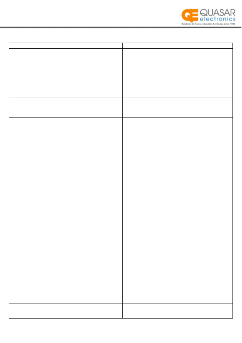
TROUBLESHOOTING REFERENCE
SYMPTOM
POSSIBLE
CAUSE
SOLUTIONS
ON/OFF switch is
switched on, LED does
not light, buzzer is off, no
AC output.
There is no DC power from
the input terminals
1.
Check the continuity of the DC power input, ensure all
batteries are working or DC power supply is on.
2.
Check that the battery inline fuse is intact. Replace if
blown.
3.
Check that all connections in the power bank battery
array are tight.
Polarity of the DC input has
been reverse connected
Correct the polarity of the input connections, check and
replace any blown up fuses. If unit remain unresponsive,
permanent damage may have occurred, please contact
technical repair.
Buzzer sounded once
only when switch on,
power LED on, no AC
output.
1.
Loose AC output
connections.
2.
Short circuit on AC output
load.
1.
Ensure fully plugged in on AC output sockets.
2.
Ensure connected load is not faulty.
Contact technician/retailer is problem unsolved.
Buzzer sounds 2 times
and red light flashes 2
times every 8 seconds
Voltage across the DC input
terminals dropped below
10.8±0.2Vdc (on 12V input
inverter), 21.6±0.4Vdc (on
24V input inverter).
1.
Check battery level, if it is low please recharge before
continuing use.
2.
On the battery cables used check the cross-section
area of the conductor is no thinner than recommended,
use thicker cables if required. Also avoid connecting
inverter to input power at a long distance as voltage
drops along the length of the cable.
3.
Ensure input connections are tight.
Buzzer sounds 3 times
and red light flashes 3
times every 8 seconds
Voltage across the DC input
terminals dropped below
critical range 10.2±0.2Vdc (on
12V input inverter),
20.4±0.4Vdc (on 24V input
inverter).
1.
Check battery level, if it is low please recharge before
continuing use.
2.
On the battery cables used check the cross-section
area of the conductor is no thinner than recommended,
use thicker cables if required. Also avoid connecting
inverter to input power at a long distance as voltage
drops along the length of the cable.
3.
Ensure input connections are tight.
Buzzer sounds 4 times
and red light flashes 4
times every 8 seconds
Input DC power is higher than
inverter’s maximum limit
15.5±0.2Vdc (on 12V input
inverter),
31±0.4Vdc (on 24V input
version)
1.
Check and ensure the DC input voltage across the
input terminal is no more than 15/30Vdc.
2.
Ensure that the maximum charging voltage of the
battery charger /alternator / solar charge controller is no
more than 15/30Vdc
3.
Ensure that an un-regulated DC power supply and
charger are not used to charge the power bank while in
use.
Buzzer sounds 5 times
and red light flashes 5
times every 8 seconds
System overheating, inner
temperature has reached 75°C
1.
Switch off for 15 min to cool down the unit before
switch back on. Check that the fan is working. If not, the
fan/fan control circuit may be defective, please contact
retailer.
2.
If the fan works, ensure that the ventilation slots on
the front and back of the inverter are not obstructed
3.
If the fan is working and ventilation ports are not
obstructed, check that enough air space is available for
ventilation and cooling. Also check that the air
temperature is less than 45ºC which is the maximum limit
for the inverter to work in.
4.
Reduce the load to reduce the heat output.
5.
If inverter is under full load, an external fan will help to
cool down the unit.
Red light constantly
flashing when switched
on
The load is higher than the
inverter’s rated continuous
power
The appliance requires an inverter with a higher rated
power to start up

User Manual
INTERFERENCE:
It is not suggested to use modified sine wave inverter to power acoustic equipment. As the modified sine
wave power signal will induce distortion signal to the sound signal within equipment if circuitry is not well
isolated. This will cause a continuous “hum” or “buzz” background noise.
Also inverter may cause interference to TV signals. The interference can be minimising by adding an inline
aerial filter between the TV and TV antenna. If the interference become obvious especially in weak signal
areas, please try to place the inverter as far away from the antenna as possible and use high quality
screened coax cable.
WARRANTY
All inverters are covered against defects in components and build quality for period of up to 12 months
from the day of purchase. Valid receipt or bank statement to show purchase date is within last 12 months
must be shown for warranty to be valid.
Any unit that has been misused, altered or accidentally damaged will not be covered by warranty.
Mercury will not be responsible for any damage cause as result of misconduct.
SPECIFICATION:
SPEC
MODEL
SSI000UK
SSI00
1
UK
SSI00
2
UK
SSI00
3
UK
SSI00
4
UK
SSI00
5
UK
INPUT
VOLTAGE
10.8
-
15.5Vdc 21.6-31Vdc
10.8
-
15.5Vdc 21.6-31Vdc 10.8-15.5Vdc 21.6-31Vdc
EFFICIENCY Over 80% Efficiency
POWER
TYPE
Open
&
Seal
Lead
Acid
Battery,
Regulated
DC
Alternator
OUTPUT
CONTINUOUS
POWER 150W 150W 300W 300W 600W 600W
SURGE
POWER
200%
of
Continuous
Power
for
2
sec
to
help
starting
up
AC
VOLTAGE
230Vac
±
10%
50Hz
SIGNAL WAVE
FORM Modified Sine Wave
USB 5Vdc, 1.0A
PROTECTIONS
2 Phases Low Battery Protection (warning and critical shutdown),
Input Over Power Protection,
Overload Protection,
Over Heat Protection,
Short Circuit Protection
DIMENSION
(mm)
16x10x5.5
16x10x5.5
16x10x5.5
16x10x5.5
19x10x5.5
19x10x5.5
WEIGHT
(kg)
0.65
0.65
0.65
0.65
0.83
0.83
AMBIENT WORK
TEMPERATURE -15°C – 45°C
STORAGE
TEMPERATURE
-40°C – 85°C
HUMIDITY
20%
-
90%
non
-
condensing

User Manual
SPEC
MODEL
SSI00
6
UK
SSI00
7
UK
SSI00
8
UK
SSI00
9
UK
SSI0
1
0
UK
SSI0
11
UK
INPUT
VOLTAGE
10.8
-
15.5Vdc 21.6-31Vdc
10.8
-
15.5Vdc 21.6-31Vdc 10.8-15.5Vdc 21.6-31Vdc
EFFICIENCY Over 80% Efficiency
POWER TYPE Open & Seal Lead Acid Battery, Regulated DC Alternator
OUTPUT
CONTINUOUS
POWER 1000W 1000W 1500W 1500W 2500W 2500W
SURGE
POWER 200% of Continuous Power for 2 sec to help starting up
AC
VOLTAGE
230Vac
±
10%
50Hz
SIGNAL WAVE
FORM Modified Sine Wave
USB
5Vdc,
1.0A
PROTECTIONS
2 Phases Low Battery Protection (warning and critical shutdown),
Input Over Power Protection,
Overload Protection,
Over Heat Protection,
Short Circuit Protection
DIMENSION
(mm)
26x15x7
26x15x7
30.5x22x9
30.5x22x9
37.5x22x9
37.5x22x9
WEIGHT
(kg)
1.87
1.87
3.55
3.55
5.88
5.88
AMBIENT WORK
TEMPERATURE -15°C – 45°C
STORAGE
TEMPERATURE
-40°C – 85°C
HUMIDITY
20%
-
90%
non
-
condensing

User Manual
APPENDIX:
Below table show recommended accessories specification for each model of inverter:
MODEL INPUT VOLTAGE DC INPUT CABLE FUSE
BATTERY
CAPACITY
SSI000UK
12V
1 pair
2.5mm
2
35A
≥25Ah
SSI00
1
UK
24V
1 pair
2.5mm
2
20A
≥15Ah
SSI00
2
UK
12V
1 pair
4mm
2
35A
≥50Ah
SSI00
3
UK
24V
1 pair
2.5mm
2
20A
≥25Ah
SSI00
4
UK
12V
1 pair
6mm
2
35A*4
≥100Ah
SSI00
5
UK
24V
1 pair
4mm
2
20A*4
≥50Ah
SSI00
6
UK
12V
1 pair 10mm
2
35A*4
≥160Ah
SSI00
7
UK
24V
1 pair
6mm
2
20A*4
≥80Ah
SSI00
8
UK
12V
2 pairs
10mm
2
35A*6
≥250Ah
SSI00
9
UK
24V
2 pairs
6mm
2
20A*6
≥125Ah
SSI0
1
0
UK
12V
2 pairs
16mm
2
35A*8
≥320Ah
SSI0
11
UK
24V
2 pairs
10mm
2
20A*8
≥160Ah
This product is classed as Electrical or Electronic equipment and should not be disposed with other
household or commercial waste at the end of its useful life. The goods must be disposed of according
to your local council guidelines.
Errors and omissions excepted.
Copyright© 2022. Quasar Electronics Ltd.
This manual suits for next models
11
Table of contents
Popular Inverter manuals by other brands

Mitsubishi
Mitsubishi FREQROL Z200-U instruction manual

Alpermann+Velte
Alpermann+Velte AV-MTD G 30 TTT operating manual

Huawei
Huawei SUN2000 Series user manual

SunSynk
SunSynk SUN-25K-SG01HP3-EU-BM2 Installer manual

Phocos
Phocos Any-Grid PSW-H-6.5kW-120/48V quick start guide

SMA
SMA SUNNY ISLAND 4.4M Replacement of Various Components