Budmat FWD2HBM BI 2x4 Parts list manual

ASSEMBLY AND USAGE INSTRUCTIONS
for Photovoltaic Module Support Structure
FWD2HBMBI
2x4 ,2x6

2
ASSEMBLY INSTRUCTION
Table of Contents
GENETAL INFORMATION ....................................................................................................3
1.
STRUCTURE VARIANTS. ..............................................................................................3
2.
SAFETY INFORMATION ................................................................................................3
3.
PRODUCT USE .............................................................................................................4
a. Maintenance.................................................................................................................4
b. Cleaning.......................................................................................................................4
4.
PACKAGING, STORAGE AND TRANSPORT ...............................................................4
5.
ASSEMBLY. GENERAL INFORMATION .......................................................................5
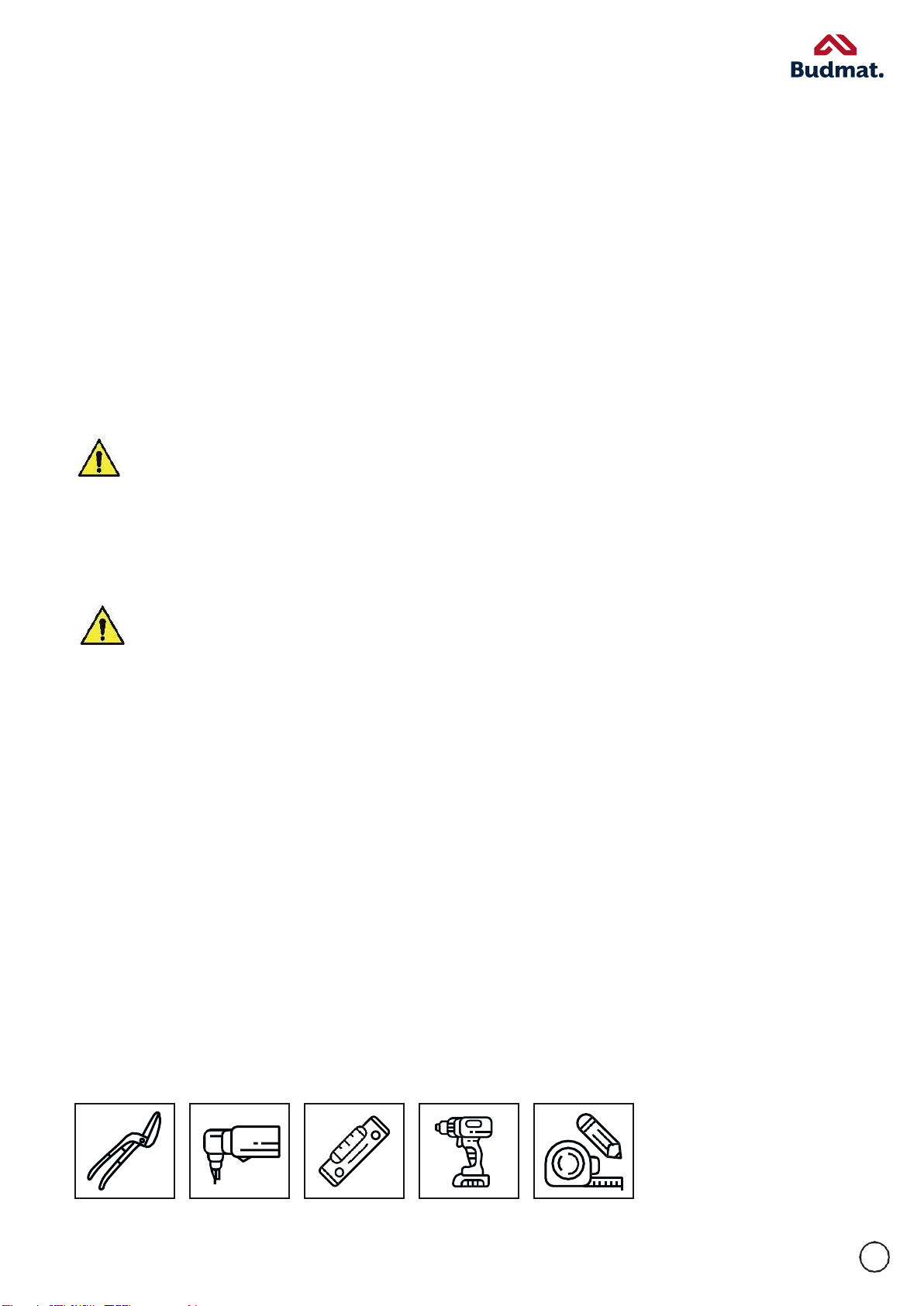
a. Tools ............................................................................................................................5
ASSEMBLY INSTRUCTION ........................................................................................................ 6
1. COMPONENTS....................................................................................................................... 6
1.1. BASIC STRUCTURE COMPONENT KIT ..................................................................... 6
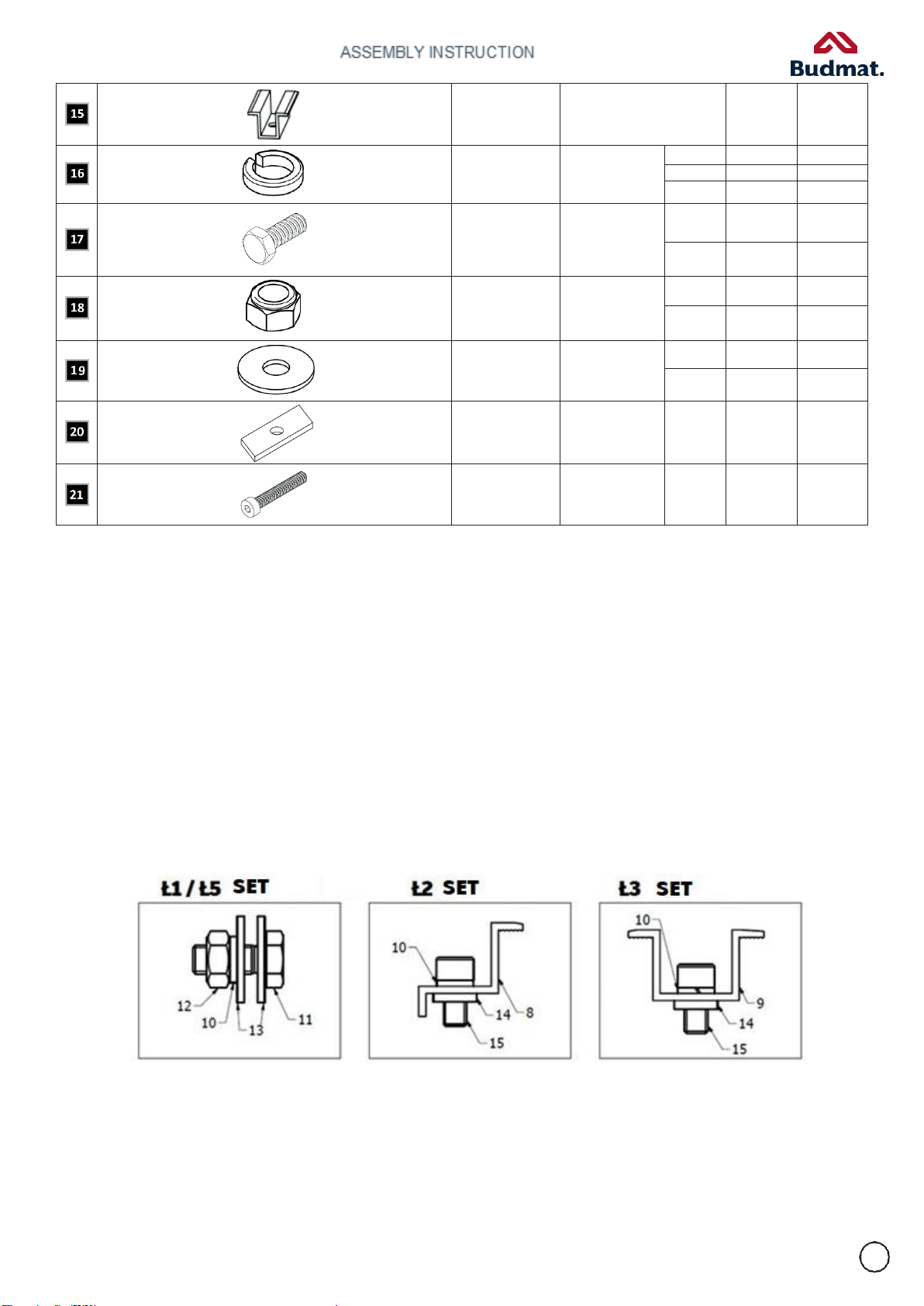
1.2. CONNECTING SETS ..................................................................................................... 7
1.2.1. CONNECTION PATTERNS .................................................................................... 7
2. ASSEMBLY ............................................................................................................................. 8
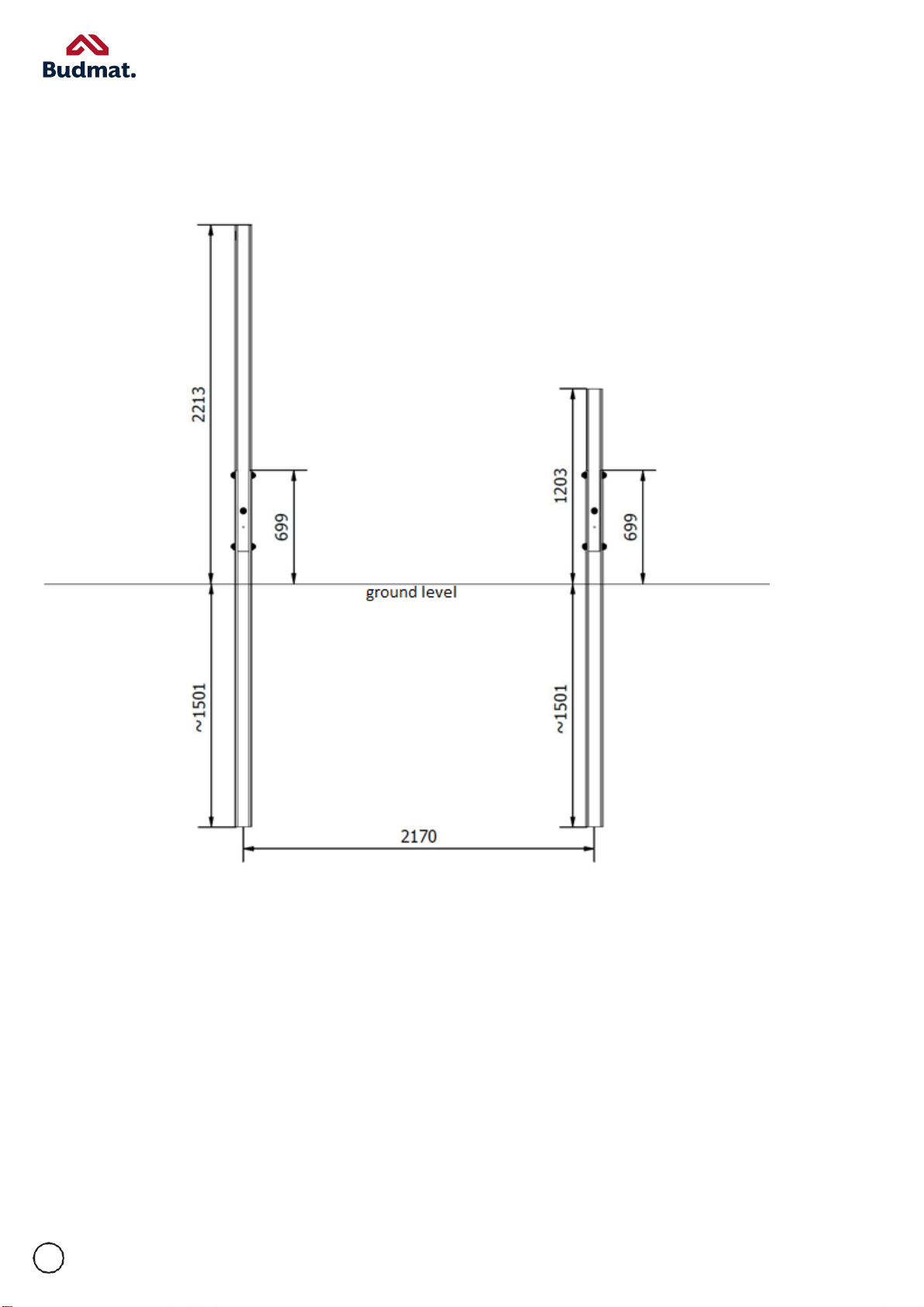
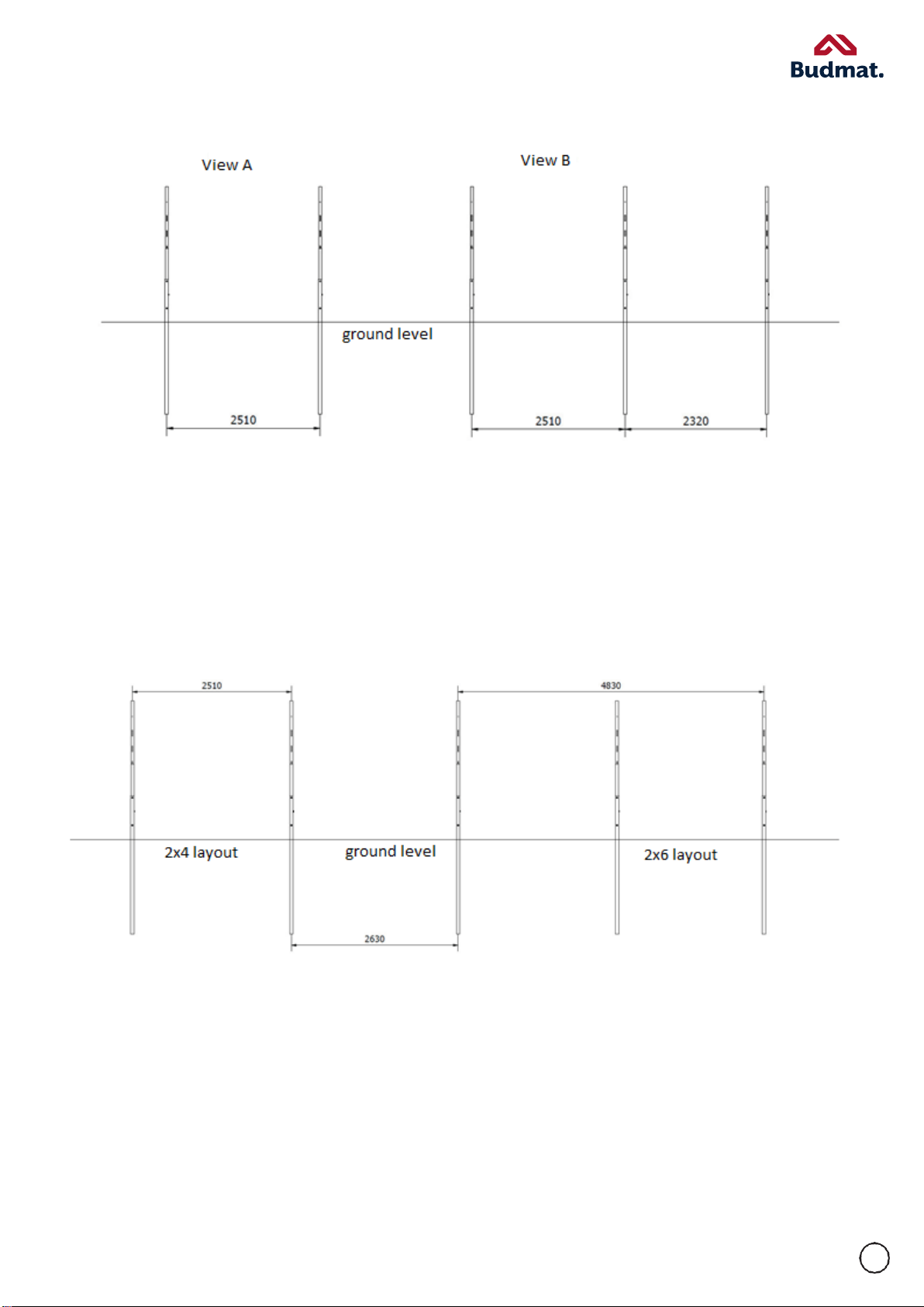
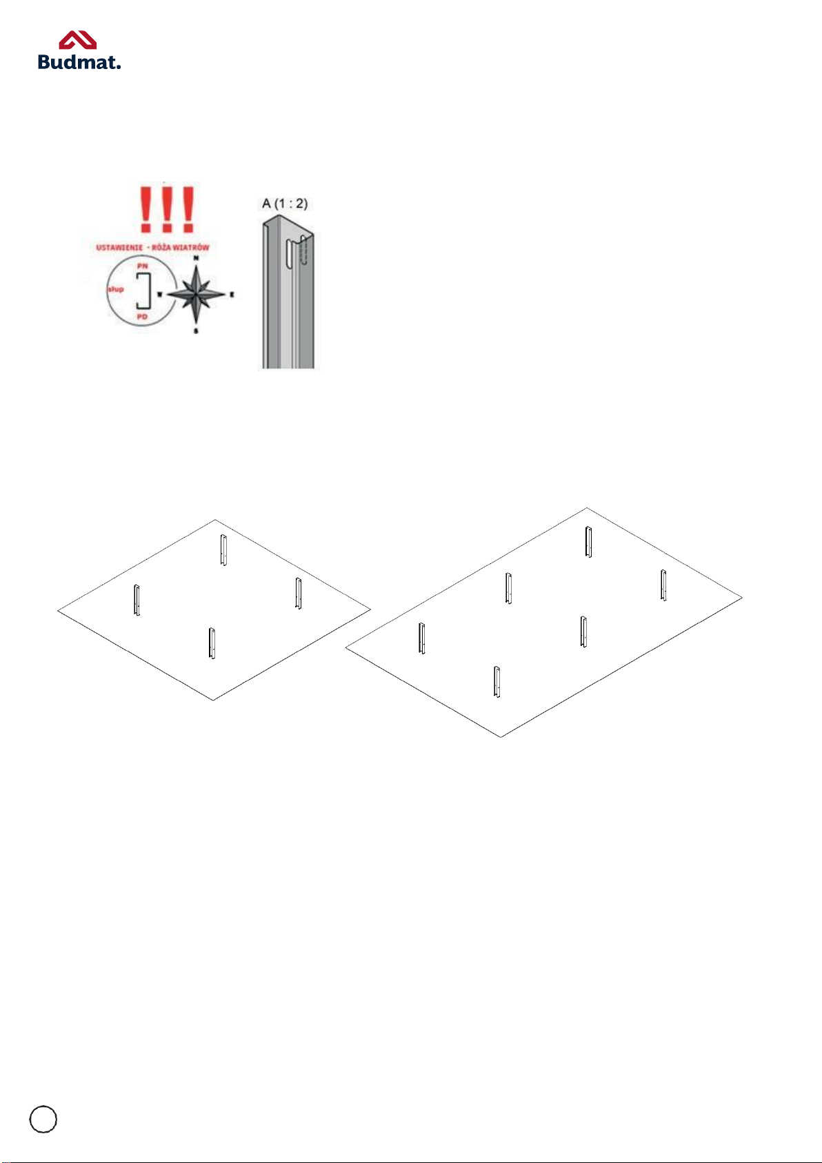
2.1. POST LAYOUT ............................................................................................................... 8
2.1.1. POST MOUNTING .................................................................................................10
2.2. BINDER ASSEMBLY .....................................................................................................11
2.3. RAFTER ASSEMBLY ....................................................................................................13
2.4. BRACE ASSEMBLY ......................................................................................................15
2.5. PV PANEL ASSEMBLY ................................................................................................16
2.6. INVERTER MOUNTING ASSEMBLY .............................................................................16
TABLE OF FIGURES ...................................................................................................................17

ASSEMBLY INSTRUCTION
MONTAŻU
3
GENERAL INFORMATION
FWD 2 structures are complete systems of free-standing, ground-mounted support structures for
photovoltaic panels manufactured in our own machine park. Each PV structure consists of components made of
high-quality steel with Magnelis ZM310 and ZM 410 coatings, and it comes with an essential set of screws, nuts,
clamps and washers.
This assembly instruction is intended for the Buyer/User to get familiar with the structure, its operating
principle, storage and transportation guidelines, and correct assembly of the components.
1.
STRUCTURE VARIANTS
2x4 2x6
2.
SAFETY INFORMATION
Photovoltaic structures should be assembled by experienced and properly equipped professional teams only.
During the assembly, use and repair of products covered by this instruction, generally applicable occupational
health and safety regulations should be followed. It is therefore, among others, necessary to:
Wear personal protective equipment such as helmet and other types of protective clothes
Use ladders, scaffoldings and electric lifting equipment with proper certificates confirming their
usability
Secure the area in which there is work in progress against unauthorised entry
Have a valid medical certificate for working at heights.

ASSEMBLY INSTRUCTION
4
During works at heights, as well as while climbing and descending, there is a risk of falling. Follow
accident prevention rules and regulations strictly and use proper fall protection equipment.
While carrying out works related to the assembly of photovoltaic structures, your hand may get
crushed or injured on sharp edges. Wearing protective gloves is therefore recommended.
3.
PRODUCTE USE
a.
Maintenance
In order to ensure correct operation and a long useful time of the system, inspections should be carried
out on a yearly basis. Check whether the fastening screws and ordinary screws and bolts are tightened and in
the correct position.
Stepping on the structure and putting any other type of load on it is strictly prohibited.
Should you notice that any of the fastening components are loosened, secure the area around the
structure against unauthorised entry and perform a repair in compliance with OSH regulations and provisions of
the instructions.
b.
Cleaning
In order to maintain the attractive appearance of the fastening structure, clean it regularly. Clean
components of the frame provide for a nicer look, longer durability and better functioning of the structure.
System components are best cleaned with water and sponge. However, neutral detergents may also be
used.
Do not use alkaline cleaning agents! The glass on the panels is sensitive to
alkaline substances.
4.
PACKAGING, STORAGE,TRANSPORT
The products should be packed in an original BUDMAT package in a manner preventing the loss of any component
of the particular system. After receiving the delivery, please always check the product for its quality and possible lack of
components in the respective kit(s).
The vehicle transporting Magnelis-coated profiles should be adapted to this kind of transportation.
The loading,unloadingandproperfasteningofthegoodsforthetimeoftransportshouldbemadeeasyfortheperson
carryingouttheseactivities.

ASSEMBLY INSTRUCTION
5
Complete assembly systems are delivered to the recipient with protection against damage. The
completeness of the delivery as well as appropriate condition of the delivered profiles shall be confirmed in
writing by the recipient on the Stock Issue Confirmation or on any other equivalent document, on which
comments regarding the product, provided there are any, should be written down
.
5.
ASSEMBLY - GENERAL INFORMATION
The assembly is to be conducted in accordance with the instructions issued by Budmat.
Adapt the foundation of the structure to the local soil conditions.
Recommended tightening torques during the assembly:
M8 hexagon socket screws, mid and end clamps: 10-11 Nm
Duringthetighteningofthescrewstothemoduleframe,therhombicMagnelisnutmaybecomedeformedatthetorqueof11Nm.
Thisdeformationisacceptable.
Screws and nuts: M10: 44-48 Nm (for tZn screws)
M12: 51-55 Nm (for A2-70 screws)
77-81 Nm (for tZn screws)
Tighteningfastenerswithimpactdriversand/orwrenchesisprohibited.
In order to prevent the fasteners from seizing, it is recommended to use a lubricant (eg. teflon grease) on
joints exposed to dust, water etc.
It is prohibited to interfere with the structure by drilling holes, grinding its edges, cutting it or carrying out other activities that
may damageits protectivelayer,unlesssuchanactivityisadmissibleaspertheinstructionorBudmatconsentstosuchanactivity being
carriedout.
The upper parts of the posts may become deformed while driven into the ground. In that case, the
occurring deformations should be secured with zinc paint along the scratch. Remove any soiling from the
components that has accumulated during the assembly immediately before proceeding to the next assembly
phase.
a.
Tools
Required tools

ASSEMBLY INSTRUCTION
6
ASSEMBLY INSTRUCTION
1.
COMPONENTS
Structure configurations:
Modules in vertical alignment in layouts: 2x4, 2x6. Tilt angle: 25˚
1.1.
BASIC STRUCTURE COMPONENT KIT
NO
COMPONENT
SYMBOL
NAME
LAYOUT
2x4
LAYOUT
2x6
FWD2 HBM BI KD
L2200
RAFTER
5
7
FWD2 HBM BI KG
L1824
5
7
FWD2 HBM BI MF1
L2200
INVERTER
MOUNTING
2
2
FWD2 HBM BI MF2
L840
2
2
FWD2 HBM BI P1
L1560
BINDER
2
4
FWD2 HBM BI P2
L1560
2
4
FWD2 HBM BI P3
L1560
2
2
FWD2 HBM BI P4
L1560
2
2
FWD2 HBM BI SDP
L1004
FRONT POST,
TIGHTENED
2
3
FWD2 HBM BI SDT
L2014
REAR POST.
TIGHTENED
2
3
FWD2 HBM BI SW
L2200
FRONT POST,
DRIVEN
4
6
FWD2 HBM BI T1
L2200
BRACE
2
2
FWD2 HBM BI T2
L1301
2
2
END CLAMP
8
8

7
MID CLAMP
12
20
SPRING
WASHER
M8
20
28
M10
80
110
M12
18
26
HEXAGON BOLT
M10x30
80
110
M12x30
18
26
M12 / M10 NUT
M10
80
110
M12
18
26
ENLARGED
WASHER
M10
160
220
M12
36
52
RHOMBIC
WASHER
M8
20
28
HEXAGON
SOCKET SCREW
M8x35
20
28
1.2.
CONNECTING SETS:
Ł1 –M12 HEXAGON BOLT(11) + M12 ENLARGED WASHER(13) (2 pcs.) + M12 SPRING WASHER(10) + M12 NUT(12)
Ł2 –M8x35 END CLAMP(8) + HEXAGON SOCKET SCREW(15) + SPRING WASHER(10) + RHOMBIC WASHER(14)
Ł3 –M8x40 MID CLAMP(9) + HEXAGON SOCKET SCREW(15) + SPRING WASHER(10) + RHOMBIC WASHER(14)
Ł5 –M10 HEXAGON BOLT(11) + M10 ENLARGED WASHER(13) (2 pcs.) + M10 SPRING WASHER(10) + M10 NUT(12)
1.2.1. CONNECTION PATTERNS

8
ASSEMBLY INSTRUCTION
2.
ASSEMBLY
2.1.
POST LAYOUT
Rys. 1 Post spacing: North <-> South
REAR POST AND FRONT POST CONSIST OF TWO SECTIONS EACH:
I - DRIVEN INTO THE GROUND: • FWD2 HBM BI SW L2200
II - CONNECTED: • FWD2 HBM BI SDT L2014
• FWD2 HBM BI SDP L1004

ASSEMBLY INSTRUCTION
9
Fig. 2 Post spacing: East <–> West VIEW A –2x4 Layout, VIEW B –2x6 Layout
POST SPACING BETWEEN TWO ADJOINING TABLES:
Distance between tables: For vertical layout, 100mm between purlins are standard. Mark the
distances between the post in particular tables before the assembly.
Fig. 3 Post spacing between tables

ASSEMBLY INSTRUCTION
10
2.1.1.
POST MOUNTING
The post are mounted as per wind rose pattern.
Fig. 4 WIND ROSE - Post positioning
SECTION DRIVEN INTO THE GROUND: FWD2 HBM BI SW L2200
Fig. 5 POST LAYOUTS IN 2x4 AND 2x6 TABLES
JOIN THE POSTS WITH A Ł5 CONNECTING SET

ASSEMBLY INSTRUCTION
11
Fig. 6 MANNER AND POINTS OF POST CONNECTION
2.2.
BINDER ASSEMBLY
Fig. 7 2x4 and 2x6 TABLE LAYOUTS
Before assembling the binders, connect the particular binders with a Ł5 connecting
set. Join the binders in the manner shown below and connect them with 3 connecting
sets.

ASSEMBLY INSTRUCTION
12
Fig. 8 ASSEMBLY OF BINDERS IN A 2x4 LAYOUT
Fig. 9 ASSEMBLY OF BINDERS IN A 2x6 LAYOUT
CONNECT THE BINDER TO THE POST WITH A Ł1 CONNECTING SET.
Fig. 10 Binder connection points in 2x4 and 2x6 layouts

ASSEMBLY INSTRUCTION
13
Fig. 11 Binder connection
2.3.
RAFTER ASSEMBLY
Fig. 12 WIND ROSE - Rafter positioning
Before connecting the rafters to the
binders, connect the particular rafter
components with a Ł5 connecting set. Connect
the rafters in the manner shown below with 4
connecting sets.
Fig. 13 RAFTER ASSEMBLY

ASSEMBLY INSTRUCTION
14
Fig. 14 Distribution of rafters in 2x4 and 2x6 tables
CONNECT EACH RAFTER TO THE REAR AND FRONT BINDER
WITH A Ł1 CONNECTING SET.
Fig. 15 Rafter connection point

15
ASSEMBLY INSTRUCTION
2.4.
BRACE ASSEMBLY
Before connecting the BRACES to the POSTS, connect their particular components with a Ł5 connecting
set. Connect the BRACES in the manner shown below with 3 connection sets.
WHEN CONNECTING THE BRACE TO A 2X4 TABLE, ITS FINAL LENGTH MUST BE L2741.
WHEN CONNECTING THE BRACE TO A 2X6 TABLE, ITS FINAL LENGTH MUST BE L3101.
The length is adjusted with “beans” included in the FWD2 HBM BI T1 L2200 component.
Fig. 16 BRACE CONNECTION
BRACES CONNECTED IN SUCH A MANNER ARE READY TO BE FASTENED TO THE POSTS.
Fig. 17 BRACE FASTENING MANNER AND POINTS

16
ASSEMBLY INSTRUCTION
2.5.
PV PANEL ASSEMBLY
Assemble your PV panels in accordance with the instruction issued by the manufacturer.
ASSEMBLE THE PANELS WITH A Ł2 AND Ł3 CONNECTING SET
Fig. 18 PANEL DISTRIBUTION IN 2x4 and 2x6 LAYOUTS
Fig. 19 Module assembly

17
2.6.
INVERTER MOUNTING ASSEMBLY
ASSEMBLE THE INVERTER MOUNTING WITH A Ł5 CONNECTING SET
Before connecting the INVERTER MOUNTING to the POSTS, connect their particular
components with a Ł5 connecting set. Connect the MOUNTINGS in the manner shown below with
3 connecting sets.
The final inverter mounting length must be L2620.
Fig. 20 INVERTER MOUNTING CONNECTION POINTS
Fig. 21 INVERTER MOUNTING ASSEMBLY POINTS IN 2x4 and 2x6 LAYOUTS

18
TABLE OF FIGURES
Fig. 1 Post spacing: North <-> South
................................................................................................... 8
Fig. 2 Post spacing: East <–> West
...................................................................................................... 9
Fig. 3 Post spacing between tables
..................................................................................................... 9
Fig. 4 WIND ROSE - Post positioning ..................................................................................................... 10
Fig. 5 POST LAYOUTS IN 2x4 AND 2x6 TABLES....................................................................................... 10
Fig. 6 MANNER AND POINTS OF POST CONNECTION............................................................................ 11
Fig. 7 2x4 and 2x6 TABLE LAYOUTS ....................................................................................................... 11
Fig. 8 ASSEMBLY OF BINDERS IN A 2x4 LAYOUT ................................................................................... 12
Fig. 9 ASSEMBLY OF BINDERS IN A 2x6 LAYOUT ................................................................................... 12
Fig. 10 Binder connection points in 2x4 and 2x6 layouts ..................................................................... 12
Fig. 11 Binder connection ..................................................................................................................... 13
Fig. 12 WIND ROSE - Rafter positioning ................................................................................................ 13
Fig. 13 RAFTER ASSEMBLY ..................................................................................................................... 13
Fig. 14 Distribution of rafters in 2x4 and 2x6 tables ............................................................................. 14
Fig. 15 Rafter connection point ............................................................................................................ 14
Fig. 16 BRACE CONNECTION ................................................................................................................. 15
Fig. 17 BRACE FASTENING MANNER AND POINTS ................................................................................ 15
Fig. 18 PANEL DISTRIBUTION IN 2x4 and 2x6 LAYOUTS
.....................................................................16
Fig. 19 Module assembly
...................................................................................................................16
Fig. 20 INVERTER MOUNTING CONNECTION POINTS............................................................................ 16
Fig. 21 INVERTER MOUNTING ASSEMBLY POINTS IN 2x4 and 2x6 LAYOUTS
...................................... 16

This manual suits for next models
1
Table of contents