Greatwatt Energy S-700 User manual

Wind Generator
S-700
Owner's Manual
Version 1.0
Serial Number:
Inner Controller

NOTICES:
This manual contains all necessary information for assembling, testing, operating,
and maintaining this Wind Generator. Please read it carefully and retain it for future
reference.
We have made every effort to ensure that the information presented in this manual is
accurate but assumes no responsibility for any errors or omissions. Users of this
information and products assume full responsibility and risk.
All specifications are subject to change without notice.
Wind Generators, like other sources of electrical power, must be installed following
the guidelines established by state and local regulations. Consult a local electrical
contractor or the local planning and zoning office for details and regulations.
For your convenience and protection write the serial number of your Wind Generator
on the front of this manual. Store your purchase invoice with this manual as well.
You will need this information in the event of a warranty claim. It also helps our
customer service department when you have questions about your Wind Generator.
Thank you.
Manufactured in CHINA by:
GREATWATT ENERGY, LTD.,
Suzhou, China.
Web: www.greatwatt.com
Greatwatt, GT, S-600, S-700, S-800 and Wind Module
are trademarks of Greatwatt Energy, Ltd.,
©2012 Greatwatt Energy

Important Features of S-700
AERODYNAMICS & ELECTRONICS & TELEVISION
Smallest and Most Powerful: With the highly efficient blades, controller and alternator,
S-700 can provide the maximum output power in the world at the same size, weight
and rotor diameter.
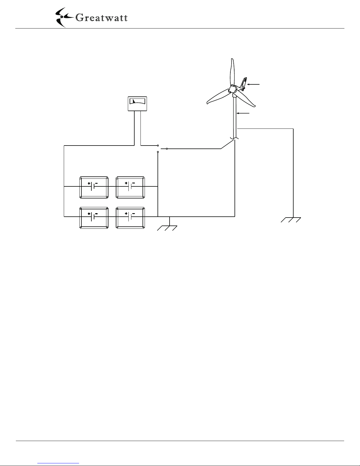
Whole Protection: S-700 provide the best protection, for example, the voltage
auto-brake, slow down in strong wind (Hysteresis Braking), shut down completely
in cyclone, battery charge protect, smart protect, overtemperature protect, and so on.
Over-speed Protection: To fully “utilize” wind power, the blades will not be braked
in the speed from 0m/s to 20m/s. Once the Wind Generator “sense” the wind speed
higher than 20m/s, it will shut down completely and stop charging.
Constant Current Charge: In the same wind speed condition, when the battery is
becoming fuller and fuller, the charging current of the common wind generator will
be less and less, but S-700 can always keep steady charging current, so it can fully
make use of the wind energy, and, at the same time, it can also effectively protect
your battery!
MATERIAL
CFRP Blades: The rotor blades are made of CFRP, and manufactured by precise
injection process, so S-700 has the rigidest, the best electric and the minimal
vibrant blades.
Magnalium Frameworks: All frameworks are made of magnalium, just as the body,
the face, the hub, the yaw shaft, etc. This material is very anticorrosive and very hard.
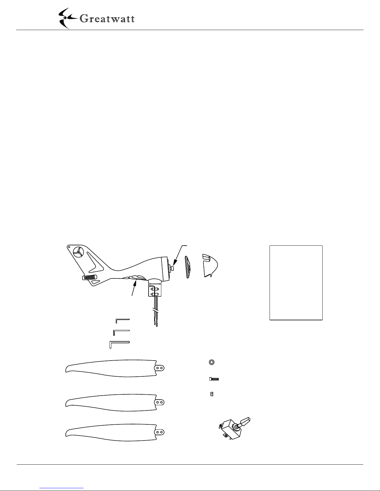
ACCESSORIES
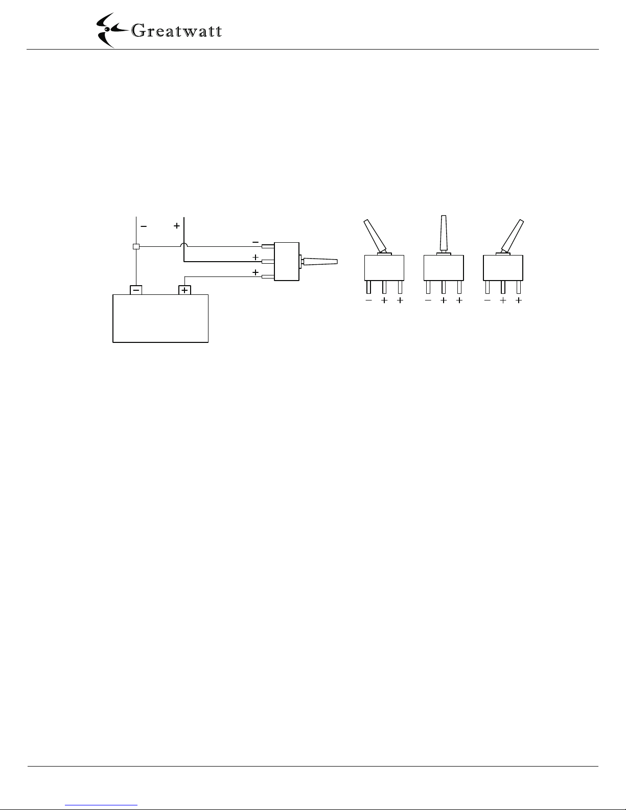
Stop Switch: We provide a stop switch (50 amps D.C.), which can be used to “stop”
the Wind Generator for service or any other reason. You will find it very useful and
necessary.
Plastic Disk: The static electricity generated from blades rotating will corrode the
hub, especially used in the sea. We provide some plastic disks to protect the
hub from corrosion.
Page 1
http://www.greatwatt.com

3
3
3
3
4
5
5
6
6
6
8
9
10
10
11
15
15
15
16
17
18
Table of Contents
1.
1.1 Mechanical Hazards
1.2 Electrical Shock Hazards
2. PACKAGE CONTENTS
3. EXPLODED VIEW
4. Electrical System
4.1 System Wiring Diagrams
4.2 Over-speed Protection
4.3 Stop Switch
4.4 Grounding
4.5 Operation Conditions
5. Siting
6. Tower
7. Installation Instructions
7.1 Required Tools
7.2 Pre-Check
7.3 Installation Operation
8. Trouble Shooting
8.1 Mechanical System
8.2 Electrical System
8.3 Elevation
9. Maintenance
10. Warranty Card
SAFETY PRECAUTIONS
10
7
Page 2
http://www.greatwatt.com

Page 3
1. SAFETY PRECAUTIONS
Safety must be the primary concern as you plan the location, installation and operation
of the Wind Generator. There are inherent dangers involved with any electrical and/or
mechanical equipment.
1.1 MECHANICAL HAZARD
Do not approach the machine while the blades are spinning-they can cause serious
injury!
CAUTION: DO NOT INSTALL THE WIND GENERATOR WHERE ANYONE CAN
APPROACH THE PATH OF THE BLADES.
1.2 ELECTRICAL SHOCK HAZARD
The Wind Generator can produce higher than nominal voltages when running open
circuit. Keep the output wires shorted initially and carefully follow the installation
instructions.
2. PACKAGE CONTENTS
Compare the parts shown in the following figure to ensure that the contents of the box
contain all necessary parts.
4mm Hex Key
5mm Hex Key
8mm Hex Key
Rotor Blades ( 3 )
M6-25 Socket Head Cap Screw ( 6 )
M6 Nut ( 6 )
Stop Switch
Owner's
Manual
Nose
Cone
Hub
Alternator Shaft
Main Body
Yaw
Shaft
LED
Plastic Disk ( 6 )
http://www.greatwatt.com

Page 4
3. EXPLODED VIEW
Hub
M6-25
Blades(3)
M6
Face
Face Bearing
-Outer
Face Bearing
-Inner
Gasket
4mm
M5-45
Face
O-Ring
Stator
Rotor
Brushes
Controller
LED
Body Snap Ring
Body Bearing
Body
M6-60 Screw(1)
Slip Ring
Yaw Snap Ring
Yaw Body
Yaw Clamp
Rubber
Pad
M5-35
Screw (4)
M5
Nut (4)
Gasket
5.5mm
Nose
M16
Plastic
Rubber
Gasket
Disk (6)
Snap Ring
Cone
Screw (6)
Screw (3)
NUT
Nut (6)
http://www.greatwatt.com
Grounding
cable

Page 5
4. ELECTRICAL SYSTEM
4.1 SYSTEM WIRING DIAGRAMS
Higher input voltages from additional Wind Generators, solar panels, fuel-powered generators
etc., can trick the Wind Generator's controller into sensing the battery in full charge, and the
controller will prematurely stop charging. It will not harm the Wind Generator, just cause to
slow down or stop spin. Please disconnect the other charging sources to determine the
possible interference source.
You can wire the Wind Generator through most “power centers”. However, if you experience
interference, you must bypass it and wire the Wind Generator directly to the battery bank to
its own set of battery posts. Allow the Wind Generator to operate independently, monitor the
battery and charge is necessary.
CAUTION: DO NOT CONNECT WIND GENERATOR POSITIVE TO BATTERY NEGATIVE
AND WIND GENERATOR NEGATIVE TO BATTERY POSITIVE FOR EVEN A SECOND,
OR ELSE WILL DAMAGE THE WIND GENERATOR'S CONTROLLER AND VOID YOUR
WARRANTY. (IF YOU ARE UNCERTAIN OF THE POLARITY OF THE WIRES, SIMPLY SPIN
THE ROTOR SHAFT AND MEASURE THE VOLTAGE DIRECTION WITH A VOLT METER).
NOTE: One bad battery can create high voltages (16-18 volts) and stop the Wind
Generator from charging, check the condition of each individual battery.
Consult the battery manufacturer for testing individual batteries or cells.
Wind Generator
Amp Meter
Stop Switch
Tower
Tower Ground
Turbine Negative (Black Lead)
Red Lead
Turbine Positive
Earth Ground
Battery Bank
Ground Rod
http://www.greatwatt.com

Page 6
4.2 OVER-SPEED PROTECTION
Once the Wind Generator “sense” the wind speed higher than 20m/s, it will shut down
completely and stop charging.
4.3 STOP SWITCH
We provide a stop switch (50 amps D.C.), which can be used to “stop” the Wind Generator
for service or any other reason. The switch disconnects the battery and then shorts the
Wind Generator wires causing the blades to stop spinning (in high winds the blades will
spin slowly).
Black
Wire
Red
Wire Stop
Switch
Battery Closed
Circuit
Open
Circuit
Short
Circuit
CAUTION: OPEN CIRCUIT WILL DAMAGE THE WIND GENERATOR'S CONTROLLER
4.4 GROUNDING
For long-term operation and protecting the electronics, properly grounding is very
important. Grounding procedures must be followed along with any local electrical codes.
The green lead wire must be connected to the system earth ground. This is usually
done by connecting the green lead wire to a ground rod near the base of the tower.
For additional lightning and static protection, another wire should connect this ground
rod to the tower pipe.
The negative wire of your system should also be connected to a ground. This is usually
done by connecting a wire from the negative battery terminal to a nearby ground rod. Wires
with the same ratings as the positive and negative wires must connect all system grounds.
A ground electrode can be made for systems without an existing system ground from
an 8 ft. (2.4 m) section of 3/4" (19 mm) galvanized pipe or conduit, or an 8 ft. (2.4 m)
section of 5/8" (16 mm) iron or steel rod. This ground electrode must be buried
completely beneath the soil, at no more than 45 degrees from vertical, or horizontally
at least 2 1/2 ft. (75 cm) beneath the surface. It is recommended that the ground
electrode be installed as close as possible to the batteries for maximum lightning
protection. The base of the tower is also a good location for an appropriate surge
arrestor.
CAUTION: IMPROPER GROUNDING WILL DAMAGE YOUR WIND GENERATOR
AND VOID YOUR WARRANTY.
http://www.greatwatt.com
AND VOID YOUR WARRANTY!

Page 7
4.5 OPERATION CONDITIONS
http://www.greatwatt.com
SHORT CIRCUIT: Wind generator negative and positive wires directly shorting or switch the Stop Switch.
“=12.8V”:That means normal charging operation will resume when the battery voltage drops slightly below the fully charged level.
SYSTEM CONDITIONS
OPERATE
CONDITIONS
SHORT
CIRCUIT
WIND SPEED
(m/s)
BATTERIES
VOLTAGE CHARGE DETAIL
0-3
3-20
>20
0-4
>4
Any
<14.4V(28.8V)
=14.4V(28.8V)
=12.8V(25.6V)
Any
Any
No
Yes
Yes
No
No
No
LED
Off
On
On
Fast Blink
Off
Blades no spin.
CLOSED
CIRCUIT
Slow Blink
Normal charge.
Shut down completely and wait for the battery voltage to drop.
Normal charging operation will resume.
Shut down completely for 30 minutes and then resume.
Blades no spin.
Shut down completely, but the blades still spin slowly.
3.0m/s 5.0m/s 7.0m/s 10m/s 12m/s 15m/s 18m/s ≥20m/s
RPM ( r/min ) 610 820 860 1030 1130 1250 1350
Output Voltage ( volt ) 12.3 12.4 12.5 12.6 12.8 13.2 13.5
Charge Current ( amp ) 0.8 5 7 12 17 23 25
Output Power ( watt ) 10 62 88 151 218 304 337
RPM ( r/min ) 700 810 880 1030 1200 1300 1400
Output Voltage ( volt ) 24.8 25 25.1
25.2
26.2 26.5 27
Charge Current ( amp ) 0.4 3 4 7.5 10 14 16
Output Power ( watt ) 10 75 100 189 262 371 432
12V
System
24V
System
Output Voltage:12V and 24V DIY
Protect
Blades Diameter:1120mm (3.67ft)
S-700
Start wind speed: 3.0m/s
Wind Speed
Blades Material:CFRP Net Weight : 6.7kg (14.8 lb)

5. SITING
To ensure good performance from the Wind Generator, it is important that care is
taken in the site of the machine. Buildings, trees and rocky outcrops etc. disrupt the
smooth flow of wind creating a “Wind Shear” with the wind velocity nearer the ground
being slower than that higher up. Turbulence is also created by these obstructions.
Turbulence is detrimental as the swirling air causes the Wind Generator to yaw
continually thus stressing the mechanical parts and greatly increasing wear and tear.
Sharp edges
Create turbulence
Smooth, laminar airflow
2H
20H
Turbulent airflow
2H
H
Turbulent airflow created by obstructions (Ad. P. Gipe, 93)
Therefore, as a general rule the Wind Generator should be mounted twice as high as
any such obstructions. The power obtained from the wind is proportional the cube of
the wind speed, and the wind speed increases with height from the ground. A 26%
increase in wind speed from a higher tower will yield a 100% increase in power from
the Wind Generator. A little more money spent on a higher tower will harvest the same
power as 2 machines! Preference should be given to the prevailing wind direction,
but it should be noted that tall features behind the Wind Generator can also slow down
the wind flow through the Wind Generator.
The Wind Generator should be mounted on a tower a minimum of 25' (8 meters)
above any surrounding objects within a 500' (150m) radius. If this is not possible,
then place it as high as you can. If this is a roof top installation, it is important there
are no objects around the structure that may block the wind.
Page 8
http://www.greatwatt.com

Page 9
6. TOWER
Great care should be taken in the selection and preparation of the Wind Generator's
tower, as this is the most difficult and crucial aspect of the entire installation. If you
select a tower from another source or build your own, you are responsible for assuring
the tower is suitable. As with all towers, you must first evaluate your site to determine
the appropriate tower height, available space and reasonable cost.
NOTE: Guyed and freestanding towers are the most common way to install a
Wind Generator. These towers are available in all shapes, sizes and costs.
CAUTION: DO NOT INSTALL THE WIND GENERATOR WHERE THE PATH OF THE
BLADES CAN BE REACHED DURING NORMAL OPERATION! NEVER APPROACH
THE WIND GENERATOR DURING OPERATION!
Usually, the higher tower is erected, the greater the output, but also the greater cost
and effort of the installation. If purchasing a taller tower will provide significantly more
power it might offset the additional cost and effort. It's very important to mount the
Wind Generator in the best winds while being balanced by the cost and effort of the
installation.
This Wind Generator is designed to use steel pipe 1.875 inch (48mm) outside diameter,
equivalent to 1 ½ inch SCH 40 pipe, which can be used in some tower applications. If
larger pipe is used for your tower, make sure that the 1.875 inch pipe is at least 22 inch
long or will damage the blades.
CAUTION: SAFETY, ENGINEERING AND LOCAL CODES MUST BE ADDRESSED
BEFORE ATTEMPTING ANY INSTALLATION.
NOTE: The yaw wires can support loads up to a total of 155 lbs. (70kg). If the wire
weight is higher, you must install a strain relief to minimize the stress put on the
hanging wires.
NOTE: Towers must be capable of withstanding 155 lb. (70kg) of load in the
horizontal direction at the Wind Generator.
For more information about some very economical tower kits for the Wind Generator,
please refer or purchase them from your dealer/distributor.
The following list considerations must be consulted:
Number of Wind Generators
Budget
Type: guyed, freestanding or rooftop
Site: hills, trees, buildings
Ease of use
http://www.greatwatt.com

Page 10
7. INSTALLATION INSTRUCTIONS
7.1 REQUIRED TOOLS
Stop Switch (included)
Plastic Disk (included)
4mm hex key wrench (included)
5mm hex key wrench (included)
8mm hex key wrench (included)
Power cables (not included):
6 sq mm (Europe Wire Gage) stranded or #10 AWG (American Wire Gage) stranded.
Batteries (not included)
Steel Pipe: 1 1/2“, Schedule 40 steel pipe (Actual OD 1.875 inches, 48mm) (not included)
Torque wrench with 4mm, 5mm, and 8mm hex drives (not included)
Soldering iron or propane torch (not included)
Rosin core solder (not included)
Electrical tape or 1/4” (6-7mm) heat shrink (not included)
Wire strippers (not included)
Wire crimpers (not included)
7.2 PRECHECK
Follow these processes shown below to verify if your Wind Generator is working correctly.
Spin rotor shaft slowly with your fingers provided while at the same time connecting
and disconnecting the Wind Generator's positive and negative wires. With the wires
connected, the rotor shaft should become more difficult to rotate. With the wires
disconnected, it should spin freely.
Every time connect the Wind Generator's wires (RED= Positive, BLACK = Negative)
directly to the set of posts of the battery, the LED will slow blink four times to indicate
that the controller is running properly.
If these conditions shown above do not exist, please contact your dealer .
http://www.greatwatt.com

Page 11
7.3 INSTALLATION OPERATION
Choose a calm day and have someone available to help during the installation process.
1/ We recommend that mounted your Wind Generator on 1 1/2“, Schedule 40 steel pipe
(Actual OD 1.875 inches, 48mm). Larger pipes will reduce the blade tip clearance and
may cause damage to the blades. If you want to use larger pipe, refer to the figure show
below.
Please follow these steps to install your Wind Generator:
NOTE: No more than 8 feet (2.5m) of pipe should extend from the upper most
support.
CAUTION: DO NOT USE PLASTIC PIPE. USE ONLY METAL PIPE FOR TOWER.
2/ Run the wire through the pipe and drag the wires near to the batteries (Do not
connect to the battery), strip the insulation back from each set of wires.
Right
Right Wrong
USE COMMON SENSE AND PLEASE BE CAREFUL
CAUTION: DO NOT INSTALL THE WIND GENERATOR WHERE THE PATH OF THE
BLADES CAN BE REACHED DURING NORMAL OPERATION! NEVER APPROACH
THE WIND GENERATOR DURING OPERATION!
CAUTION: ALL BATTERIES MUST DISCONNECTED THROUGHOUT THE
INSTALLATION PROCESS!
NOTE: DO NOT install the blade assembly until the body is mounted on the tower.
NOTE: THE BLADE EDGES ARE SHARP. PLEASE HANDLE IT CAREFULLY.
http://www.greatwatt.com

Page 12
3/ Connect the Wind Generator to the wires and insulate the connections using either
heat shrink tubing or a quality electrical tape.
5/ Slide the yaw shaft all the way down over the end of pole being careful not to pinch
the yaw wires. Be sure to leave enough slack in the wires so that if necessary, the Wind
Generator can be removed.
4/ We provide a rubber gasket to prevent the bottom of the yaw from contacting the
top of the pole. The only contact between the tower and yaw is through the rubber pad
which will reduce the transmission of noise down the tower. Once the yaw shaft is on
the tower, firmly tighten the yaw clamp screws with the 4mm hex key to 3-5 foot pounds
(4.0-6.5Nm). Be sure that it is securely attached to the mounts.
6/ Mark both ends of all the wires with tape to identify which is negative, positive and
ground.
Wire Color- Codes:
RED = Positive
NOTE: If you are uncertain of the wires polarity, simply spin the rotor shaft and
measure the voltage direction with a volt meter.
BLACK = Negative
Rubber Gasket
http://www.greatwatt.com

Plastic Disk (6)
M6-25 Screw ( 6 )
M6 Nut ( 6 ) Plastic Disk ( 6 )
Page 13
7/ We provide 6 pieces of plastic disk to dramatically reduce the occurrence of
corrosion between the blades and hub due to electrolysis.
Note: The corrosion will be more obvious in th sea.
8/ Place one of the blades on the hub socket and insert one of the M6-20 socket head
cap screws. Place a plastic disk on the end of the screw, then place aself-locking nut (M6)
and tighten it with the 5mm hex key to 8-10 foot lbs. (10.5-13.5 N.m). Repeat this
procedure on all three blades.
CAUTION: OVER-TORQUE WILL DAMAGE THE BLADES AND WIND GENERATOR.
CAUTION: PUSHING ROTOR SHAFT INTO THE BODY WILL DAMAGE THE
CONTROLLER.
9/ Remove the M16 nut from the rotor shaft. Slide the blades assembly onto the rotor
shaft and place the nut on the shaft. DO NOT press the rotor shaft into the body.
http://www.greatwatt.com
M16 NUT

Page 14
10/ Insert the 8mm hex key into the rotor shaft and thread the nut on by spinning the
blades assembly. Holding the blades assembly and tightening the M16 nut lightly with
the 8mm hex key. Finally, spin the blades slowly to be sure they turn freely.
11/ Place the nose cone over the center line of the blades assembly and snap the nose
cone into place. Carefully check it is secure by firmly pulling on and be sure all three
edges are catch. Don't worry if the nose cone missing, it will not affect the performance
of the Wind Generator.
12/ Run all wires close to the batteries. Connect the Stop Switch, Amp Meter (if you needed)
etc., Refer to Section 4.1 for SYSTEM WIRING DIAGRAMS.
Be sure to crimp and solder the connections using the appropriate sized connectors.
CAUTION: DO NOT CONNECT TO THE BATTERIES!
CAUTION: DO NOT SCREW M16 NUT TOO TIGHTLY, OTHERWISE THE FACE BEARING
WILL BE STUCK AND THE BLADES ROTATE DIFFICULTLY!
8mm Hex Key
Nose Cone
http://www.greatwatt.com

Page 15
13/ Make sure that your system is properly grounding. Refer to Section 4.4 for GROUNDING.
CAUTION: IMPROPER GROUNDING WILL DAMAGE THE WIND GENERATOR AND
VOID YOUR WARRANTY!
14/ Carefully raise the tower and secure base and/or guy cables.
CAUTION: ENSURE THAT THE TOWER IS VERTICAL SO THAT THE WIND GENERATOR
CAN YAW (TURN INTO THE WIND) PROPERLY.
15/ Make sure that Stop Switch are in stop position, then connect wires to the batteries
(Red wire to Positive, Black wire to Negative).
16/ Turn on the Stop Switch, your will find the LED slow blink four times to indicate that
the controller is running properly.
CONGRATULATIONS! You have completed the installation process now.
If you find the blades always stall or rotate slowly even then wind is very high:
Be sure that your Stop Switch is properly installed.
Be sure that you have not any electrical shorts in the system.
If you find the blades continually rotate like “oscillating”:
Be sure that you have not any open circuit in the system.
If you find the Amp Meter has no any indication:
Be sure that your amp meter is not an averaging style and measure the current through
the positive wire.
Be sure that your amp meter is hooked up properly and connect with the proper type.
8.2 ELECTRICAL SYSTEM
8.1 MECHANICAL SYSTEM
If the blades spin “flutter” and the sound noise, please check by placing the 8mm hex key
in the rotor shaft, holding it and turn the blades assembly to tighten.
8. TROUBLE SHOOTING
If you have followed the installation instructions, but the Wind Generator still does not work
properly, please carefully review your installation and refer this section shown below.
http://www.greatwatt.com
Be sure that don not the screw M16 nut too tightly.

Page 16
If you find the Wind Generator prematurely stop charging but the batteries are
not fully charged, please check by these steps list below:
FEET
1-500ft
METER
0-150m
OUTPUT POWER
100%
500-1,000ft
1,000-2,000ft
2,000-3,000ft
3,000-4,000ft
4,000-5,000ft
5,000-6,000ft
6,000-7,000ft
7,000-8,000ft
8,000-9,000ft
9,000-10,000ft
150-300m
300-600m
600-900m
900-1,200m
1,200-1,500m
1,500-1,800m
1,800-2,100m
2,100-2,400m
2,400-2,700m
2,700-3,000m
97%
94%
91%
88%
85%
82%
79%
76%
73%
70%
Be sure that no bad batteries in the Electrical System.
Be sure that no diodes in the line between the Wind Generator and the battery.
Be sure that no undersized wires in the line between the Wind Generator and the
battery.
Be sure that no bad connections in the line between the Wind Generator and the
battery.
Be sure that measure the voltage at the battery terminals.
8.3 ELEVATION
An important fact to keep in mind is elevation. The higher a Wind Generator is from sea
level, the lower the air density. Air density is directly proportional to the output of your
Wind Generator. Here are some general numbers to keep in mind when determine the
maximum output that can be expected from a Wind Generator.
http://www.greatwatt.com

Page 17
Be sure that all electrical connections are tight and free from corrosion.
Be sure that the tower is solid and reliable.
Be sure that the yaw-shaft bolts are tightened to the appropriate torque
specification see Section 7.3.
Be sure that the blades bolts and the hub nuts are tightened to the appropriate
torque specification see Section 7.3.
Be sure that no dirt or debris buildup on the blades and body or may cause a
decrease in performance of the Wind Generator and long-term damage that is not
covered by the warranty. Wash off any buildup with clean soap and water.
Be sure that the nose cone is solid and reliable.
Be sure that no chips, no nicks and no unbalanced of the blades or may cause
severe wear, damage, and possible failure.
NOTE: Do not install individual blades. The blades are balanced as sets.
We suggest replacing the blades and bearings every five years for optimal
performance.
9. MAINTENANCE
Although this Wind Generator has been designed to run for long periods without requiring
any maintenance, reliability and performance will be enhanced if you periodically inspect
your system. Before perform any inspection, be sure to shut down the Wind Generator.
CAUTION: NEVER APPROACH THE BLADES DURING OPERATION.
Be sure that your battery water levels and add distilled water in accordance with
manufacturer's recommendation.
The following items should be checked two months after the initial installation and
then every six months thereafter:
http://www.greatwatt.com

3 YEARS
WARRANTY
WARRANTY TABLE
Owner information:
Owner name:
Company:
Address:
City: State: Zip code:
Country: Phone:
Email:
Dealer name:
Company:
Address:
City: State: Zip code:
Country: Phone:
Email:
Dealer information:
Consumer information:
What is the application?
Grid Tie Sailboat Telecommunications Cathodic protection Other
Remote home / Cabin Monitoring station Water pumping Hobby
Serial Number
Other information:
Voltage:
What is the Main reason for selecting this product?(select only one)
Performance Recommendation Warranty Price
Features Size Styling / Appearance Other
Please mail this card to your wind generator dealer/distributor or register on line.
Tower Height: Average Wind Speed Per Month:
12V
24V Type: LAND
MARINE
Model: 24V
36V
48V
Remark: Wind Turbine main body 3 YEARS warranty time,
Wind Turbine Controller 2 YEAR warranty time.
http://www.greatwatt.com
Wind Generator
S-700 Innerl Controller
Table of contents
Popular Inverter manuals by other brands

HP
HP HP 8642A/B Service manual

mr. steam
mr. steam MS-90E Installation, operation & maintenance manual

Tripp Lite
Tripp Lite PowerVerter PV700HF owner's manual

Delta
Delta M70A-260 Installation and operation manual

Delta
Delta SOLIVIA 5.0 AP G3 Operation and installation manual

MaxPower
MaxPower Sunbridge 1000 user manual

KStar
KStar KSH-3.68k-48 manual

FRONIUS
FRONIUS Symo Advanced Series installation instructions

FRONIUS
FRONIUS PRIMO GEN24 PLUS quick start guide

Tripp Lite
Tripp Lite PowerVerter RV Inverter/Charger RV750ULHW Specifications

FRONIUS
FRONIUS 10.0-3 208-240 installation instructions

Power Bright
Power Bright XR250 owner's guide