manuals.online logo
Brands
  1. Home
  2. •
  3. Brands
  4. •
  5. QUBINO
  6. •
  7. Relay
  8. •
  9. QUBINO ZMNHND1 User manual

QUBINO ZMNHND1 User manual

Qubino
The INNOVATIVE and SMALLEST
Flush 1D relay
ORDERING CODE
Z-WAVE FREQUENCY
ZMNHND1
868,4 MHz
ZMNHND2
921,4 MHz
ZMNHND3
908,4 MHz
ZMNHND4
869,0 MHz
ZMNHND5
916,0 MHz
This Z-Wave module is used for switching on or off
the electrical device (e.g. light or fan). The module
can be controlled either through Z-wave network or
through the wall switch.
The module is designed to be mounted inside a
“flush mounting box”, hidden behind a traditional
wall switch.
Module supports connection of digital temperature
sensor. It is designed to act as repeater in order to
improve range and stability of Z-wave network.
Supported switches
Module supports mono-stable switches (push
button) and bi-stable switches. The module is
factory set to operate with bi-stable switches.
Installation
Before the installation disconnect power
supply.
Connect the module according to electrical
diagram.
Locate the antenna far from metal elements
(as far as possible).
Do not shorten the antenna.
Danger of electrocution!
Module installation requires a great degree of
skill and may be performed only by a qualified
and licensed electrician.
Even when the module is turned off, voltage
may be present on its terminals. Any work on
configuration changes related to connection
mode or load must be always performed by
disconnected power supply (disable the fuse).
Note!
Do not connect the module to loads exceeding
recommended values. Connect the module only in
accordance to the below diagrams. Improper
connections may be dangerous.
Electrical installation must be protected by over
current protection fuse 10A, Tag lag T, rated
breaking capacity 1500V (ESKA 522.7..) according
to wiring diagram.
Package contents
Flush 1D relay
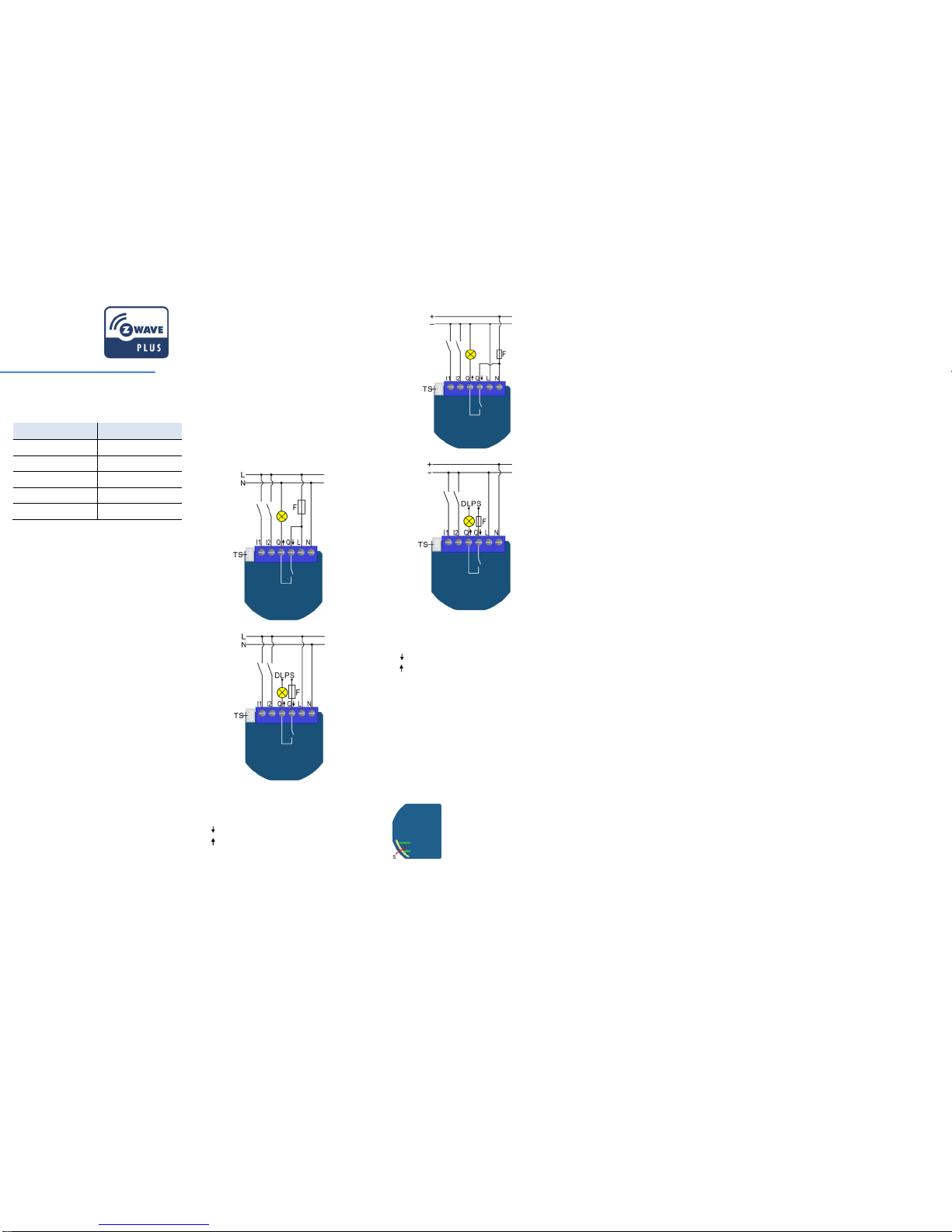
Electrical diagram 230VAC
Option for different load power supply - DPLS:
Notes for the diagrams:
Electrical diagram 24VDC
Option for different load power supply - DPLS:
Notes for the diagrams:
NOTE!
Output contact is voltage free (dry contact), so also
loads with different power supply can be
connected to the module.
NOTE: Service button S can’t be used when
module is connected to 110-230V power supply.
Durability of the module depends on applied load.
For resistive load (light bulbs, etc.) and 10A
current consumption of each individual electrical
device, the durability exceeds 100.000 switches of
each individual electrical device.
Module Inclusion (Adding to Z-wave
network)
Connect module to power supply (with
temperature sensor connected - if
purchased),
auto-inclusion (works for about 5 seconds
after connected to power supply) or
press service button Sfor more than 2 second
or
press push button I1 three times within 3s (3
times change switch state within 3 seconds).
NOTE1: For auto-inclusion procedure, first set main
controller into inclusion mode and then connect
module to power supply.
NOTE2: When connecting temperature sensor to
module that has already been included, you have
to exclude module first. Switch off power supply,
connect the sensor and re-include the module.
Module Exclusion/Reset (Removing from
Z-Wave network)
Connect module to power supply
bring module within maximum 1 meter (3 feet)
of the main controller,
enable add/remove mode on main controller
press service button Sfor more than 6 second
or
press push button I1 five times within 3s (5
times change switch state within 3 seconds) in
the first 60 seconds after the module is
connected to the power supply.
By this function all parameters of the module are
set to default values and own ID is deleted
If service button S is pressed more than 2 and less
than 6 seconds (or if push button I1 is pressed
three times within 3s) module is excluded, but
configuration parameters are not set to default
values.
Associations
Associations enables Flush 1D relay module to
transfer commands inside Z-Wave network directly
(without main controller) to other Z-Wave modules.
Associated Groups:
Root device:
Group 1: Lifeline group (reserved for
communication with the main controller), 1 node
allowed.
Group 2: basic on/off (triggered at change of the
output state and reflecting its state) up to 16
nodes.
Group 3: basic on/off (triggered at change of the
input I2 state and reflecting its state) up to 16
nodes.
Group 4: Binary Sensor Report (triggered at
change of the input I2 state and reflecting its state)
up to 16 nodes.
Group 5: Notification Report (triggered at change
of the input I2 state and reflecting its state) up to
16 nodes.
Endpoint 1:
Group 1: Lifeline group, 0 nodes allowed.
Group 2: basic on/off (triggered at change of the
output state and reflecting its state) up to 16
nodes.
Endpoint 2:
Group 1: Lifeline group, 0 nodes allowed.
Group 2: basic on/off (triggered at change of the
input I2 state and reflecting its state) up to 16
nodes.
Group 3: Binary Sensor Report (triggered at
change of the input I2 state and reflecting its state)
up to 16 nodes.
Group 4: Notification Report (triggered at change
of the input I2 state and reflecting its state) up to
16 nodes.
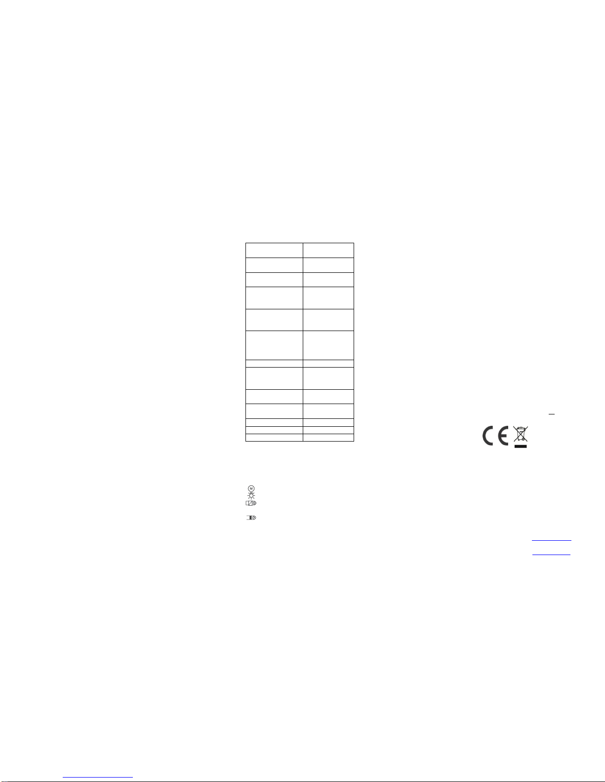
Configuration parameters
Parameter no. 1 –Input 1 switch type
Available configuration parameters (data type is 1
Byte DEC):
default value 1
0 - mono-stable switch type (push button)
1 - bi-stable switch type
Parameter no. 2 –Input 2 contact type
Available configuration parameters (data type is 1
Byte DEC):
default value 0
0 - NO (normally open) input type
1 - NC (normally close) input type
Parameter no. 10 - Activate / deactivate
functions ALL ON/ALL OFF
Available configuration parameters (data type is 2
Byte DEC):
default value 255
255 - ALL ON active, ALL OFF active
0 - ALL ON is not active ALL OFF is not active
1 - ALL ON is not active ALL OFF active
2 - ALL ON active ALL OFF is not active
Flush 1D relay module responds to commands
ALL ON / ALL OFF that may be sent by the main
controller or by other controller belonging to the
system.
Parameter no. 11 - Automatic turning off output
after set time
When relay is ON it goes automatically OFF after
time defined by this parameter. Timer is reset to
N
Neutral lead
L
Live lead
Q
Input for electrical device power supply
Q
Output for electrical device
I2
Input for switch /push button or sensor
I1
Input for switch /push button
TS
Terminal for digital temperature sensor
(only for Flush 1D relay module
compatible digital temperature sensor,
which must be ordered separately).
N
+ VDC
L
- VDC
Q
Input for electrical device power supply
Q
Output for electrical device
I2
Input for switch /push button or sensor
I1
Input for switch /push button
TS
Terminal for digital temperature sensor
(only for Flush 1D relay module
compatible digital temperature sensor,
which must be ordered separately).
S
Service button (used to
add or remove module
from the Z-Wave
network).
zero each time the module receive ON command
regardless from where it comes (push button,
associated module, controller,..).
Available configuration parameters (data type is 2
Byte DEC):
default value 0
0 - Auto OFF disabled
1 - 32535 = 1second (0,01s) –32535 seconds
(325,35s) Auto OFF enabled with define time,
step is 1s or 10ms according to parameter
nr.15
Parameter no. 12 - Automatic turning on output
after set time
When relay is OFF it goes automatically ON after
time defined by this parameter. Timer is reset to
zero each time the module receive OFF command
regardless from where it comes (push button,
associated module, controller,..). Available
configuration parameters (data type is 2 Byte
DEC):
default value 0
0 - Auto ON disabled
1 - 32535 = 1second (0,01s) - 32536 seconds
(325,35s) Auto ON enabled with define time,
step is 1s or 10ms according to parameter
nr.15
Parameter no. 15 - Automatic turning off / on
seconds or milliseconds selection
Available configuration parameters (data type is 1
Byte DEC):
default value 0
0 - seconds selected
1 - milliseconds selected
NOTE: This parameter is valid for both, turning on
and turning off parameters.
Parameter no. 30 - Saving the state of the relay
after a power failure
Available configuration parameters (data type is 1
Byte DEC):
default value 0
0 - Flush 1D relay module saves its state
before power failure (it returns to the last
position saved before a power failure)
1 - Flush 1D relay module does not save
the state after a power failure, it returns to
"off" position.
Parameter no. 63 –Output Switch selection
Set value means the type of the device that is
connected to the output. The device type can be
normally open (NO) or normally close (NC).
Available configuration parameters (data type is 1
Byte DEC):
default value 0
0 - When system is turned off the output is 0V
(NC).
1 - When system is turned off the output is
230V or 24V (NO).
Parameter no. 100 –Disable Endpoint I2 or
select Notification Type and Event
Enabling I2 means that Endpoint (I2) will be
present on UI. Disabling it will result in hiding the
endpoint according to the parameter set value.
Additionally, a Notification Type and Event can be
selected for the endpoint. Available configuration
parameters (data type is 1 Byte DEC):
Endpoint device type selection:
- notification sensor (1 - 6):
GENERIC_TYPE_SENSOR_NOTIFICATION,
SPECIFIC_TYPE_NOTIFICATION_SENSOR
default value 1
1 - Home Security; Motion Detection,
unknown location
2 - Carbon Monoxide; Carbon Monoxide
detected, unknown location.
3 - Carbon Dioxide; Carbon Dioxide detected,
unknown location.
4 - Water Alarm; Water Leak detected,
unknown location.
5 - Heat Alarm; Overheat detected, unknown
location.
6 - Smoke Alarm; Smoke detected, unknown
location.
0 - Endpoint, I2 disabled
- sensor binary (9):
GENERIC_TYPE_SENSOR_BINARY,
SPECIFIC_TYPE_NOT_USED
9 - Sensor binary
NOTE 1: After parameter change, first exclude
module (without setting parameters to default
value) and then re include the module!
NOTE 2: When the parameter is set to value 9 the
notifications are send for Home Security.
Parameter no. 110 –Temperature sensor offset
settings
Set value is added or subtracted to actual
measured value by sensor. Available config.
parameters (data type is 2 Byte DEC):
default value 32536
32536 - offset is 0.0C
From 1 to 100 - value from 0.1 °C to 10.0 °C is
added to actual measured temperature.
From 1001 to 1100 - value from -0.1 °C to
-10.0 °C is subtracted to actual measured
temperature.
Parameter no. 120 –Digital temperature sensor
reporting
If digital temperature sensor is connected, module
reports measured temperature on temperature
change defined by this parameter.
Available configuration parameters (data type is 1
Byte DEC):
default value 5 = 0,5°C
0 - Reporting disabled
1- 127 = 0,1°C - 12,7°C, step is 0,1°C
Technical Specifications
Power supply
110 - 230 VAC ±10%
50/60Hz, 24-30VDC
Rated load current of AC
output (resistive load)*
1 X 10A / 230VAC
Rated load current of DC
output (resistive load)
1 X 10A / 30VDC
Output circuit power of
AC output (resistive
load)
2300W (230VAC)
Output circuit power of
DC output (resistive
load)
240W (24VDC)
Digital temperature
sensor range (sensor
must be ordered
separately)
-50 ~ +125°C
Operation temperature
-10 ~ +40°C
Distance
up to 30 m indoors
(depending on
building materials)
Dimensions (WxHxD)
(package)
41,8x36,8x15,4mm
(79x52x22mm)
Weight (Brutto with
package)
28g (34g)
Electricity consumption
0,4W
For installation in boxes
Ø ≥ 60mm or 2M
Switching
Relay
* In case of load other than resistive, pay attention
to the value of cos φ and if necessary apply load
lower than the rated load. Max current for cos
φ=0,4 is 3A at 250VAC, 3A at 24VDC L/R=7ms.
Supported loads:
Electric motor
Convent. incandescent and halogen lights
LED and CFL bulb, low voltage halogen
bulbs with electronic transformer
Low voltage halogen bulbs with
conventional transformer
Z-Wave Device Class:
ZWAVEPLUS_INFO_REPORT_ROLE_TYPE_SLAVE_AL
WAYS_ON
GENERIC_TYPE_SWITCH_BINARY
SPECIFIC_TYPE_POWER_SWITCH_BINARY
Z-Wave Supported Command Classes:
COMMAND_CLASS_ZWAVEPLUS_INFO
COMMAND_CLASS_VERSION_V2
COMMAND_CLASS_MANUFACTURER_SPECIFIC
COMMAND_CLASS_DEVICE_RESET_LOCALLY
COMMAND_CLASS_POWERLEVEL
COMMAND_CLASS_BASIC
COMMAND_CLASS_SENSOR_BINARY
COMMAND_CLASS_NOTIFICATION_V5
COMMAND_CLASS_SWITCH_ALL
COMMAND_CLASS_SWITCH_BINARY
COMMAND_CLASS_SENSOR_MULTILEVEL_V7
COMMAND_CLASS_MULTI_CHANNEL_V4
COMMAND_CLASS_ASSOCIATION_V2
COMMAND_CLASS_MULTI_CHANNEL_ASSOCIATION_
V3
COMMAND_CLASS_ASSOCIATION_GRP_INFO_V2
COMMAND_CLASS_CONFIGURATION
COMMAND_CLASS_MARK
COMMAND_CLASS_BASIC
Endpoint 1
COMMAND_CLASS_ZWAVEPLUS_INFO
COMMAND_CLASS_VERSION_V2
COMMAND_CLASS_BASIC
COMMAND_CLASS_SWITCH_ALL
COMMAND_CLASS_SWITCH_BINARY
COMMAND_CLASS_SENSOR_MULTILEVEL_V7
COMMAND_CLASS_ASSOCIATION_V2
COMMAND_CLASS_MULTI_CHANNEL_ASSOCIATION_
V3
COMMAND_CLASS_ASSOCIATION_GRP_INFO_V2
COMMAND_CLASS_MARK
COMMAND_CLASS_BASIC
Endpoint 2 (I2):
Device Class:
ZWAVEPLUS_INFO_REPORT_ROLE_TYPE_SLAVE_AL
WAYS_ON
GENERIC_TYPE_SENSOR_NOTIFICATION
SPECIFIC_TYPE_NOTIFICATION_SENSOR
Command Classes:
COMMAND_CLASS_ZWAVEPLUS_INFO
COMMAND_CLASS_VERSION_V2
COMMAND_CLASS_SENSOR_BINARY
COMMAND_CLASS_BASIC
COMMAND_CLASS_NOTIFICATION_V5
COMMAND_CLASS_ASSOCIATION_V2
COMMAND_CLASS_MULTI_CHANNEL_ASSOCIATION_
V3
COMMAND_CLASS_ASSOCIATION_GRP_INFO_V2
COMMAND_CLASS_MARK
COMMAND_CLASS_BASIC
NOTE:The above list is valid for the product with a
temperature sensor connected to TS terminal. In
case the sensor isn’t connected then following
command class isn’t supported:
COMMAND_CLASS_SENSOR_MULTILEVEL_V7
This product can be included and operated in any
Z-Wave network with other Z-Wave certified
devices from any other manufacturers. All
constantly powered nodes in the same network will
act as repeaters regardless of the vendor in order
to increase reliability of the network.
Important disclaimer
Z-Wave wireless communication is inherently not
always 100% reliable, and as such, this product
should not be used in situations in which life and/or
valuables are solely dependent on its function.
Warning!
Do not dispose of electrical appliances as unsorted
municipal waste, use separate collection facilities.
Contact your local government for information
regarding the collection systems available. If
electrical appliances are disposed of in landfills or
dumps, hazardous substances can leak into the
groundwater and get into the food chain, damaging
your health and well-being. When replacing old
appliances with new once, the retailer is legally
obligated to take back your old appliance for
disposal at least for free of charge.
This user manual is subject to change and
improvement without notice.
NOTE: User manual is valid for module with SW
version S2 (SW version is part of P/N)!
Example: P/N: ZMNHNDx H1S2P1
Qubino
Goap d.o.o. Nova Gorica
Ulica Klementa Juga 007
5250 Solkan
Slovenia
E-mail: info@qubino.com
Tel: +386 5 335 95 00
Web: www.qubino.com
Date: 18.12.2015
Document: Qubino_Flush 1D relay
PLUS user manual_V1.2_eng

This manual suits for next models

4

Other QUBINO Relay manuals

QUBINO Flush 1 User manual

QUBINO

QUBINO Flush 1 User manual

QUBINO ZMNHAD1 User manual

QUBINO

QUBINO ZMNHAD1 User manual

Popular Relay manuals by other brands

Victron energy BP48|100 Installation

Victron energy

Victron energy BP48|100 Installation

Omron K8AK-AW Series manual

Omron

Omron K8AK-AW Series manual

Siemens SIRIUS 3UG4583-1CW30 operating instructions

Siemens

Siemens SIRIUS 3UG4583-1CW30 operating instructions

EUCHNER ESM-BA7 Series operating instructions

EUCHNER

EUCHNER ESM-BA7 Series operating instructions

MULTISPAN ELR-63 quick start guide

MULTISPAN

MULTISPAN ELR-63 quick start guide

Eaton ZW7 Series Instruction leaflet

Eaton

Eaton ZW7 Series Instruction leaflet

ABB D-3 instructions

ABB

ABB D-3 instructions

Schlage AD-Series installation instructions

Schlage

Schlage AD-Series installation instructions

ABB RELION REF615R installation manual

ABB

ABB RELION REF615R installation manual

Bitron Video RU 60 Connection instructions

Bitron Video

Bitron Video RU 60 Connection instructions

Aetechron CR-600 instruction sheet

Aetechron

Aetechron CR-600 instruction sheet

Procom ELR Series manual

Procom

Procom ELR Series manual

Guard master MINOTAUR MSR6R/T installation instructions

Guard master

Guard master MINOTAUR MSR6R/T installation instructions

Guard master Minotaur MSR15D installation instructions

Guard master

Guard master Minotaur MSR15D installation instructions

Sel SEL-2664S manual

Sel

Sel SEL-2664S manual

Rohde ST 630 manual

Rohde

Rohde ST 630 manual

Seg XRI1-IR manual

Seg

Seg XRI1-IR manual

Basler BE1-50/51M-222 instruction manual

Basler

Basler BE1-50/51M-222 instruction manual

manuals.online logo
manuals.online logoBrands
  • About & Mission
  • Contact us
  • Privacy Policy
  • Terms and Conditions

Copyright 2025 Manuals.Online. All Rights Reserved.