CONTENTS
PART A: INFORMATION FOR THE USER
1.0 GENERAL CHARACTERISTICS
2.0 INTENDED USE
3.0 OPERATION
4.0 GENERAL SAFETY STANDARDS
5.0 DESCRIPTION OF DANGER SIGNALS
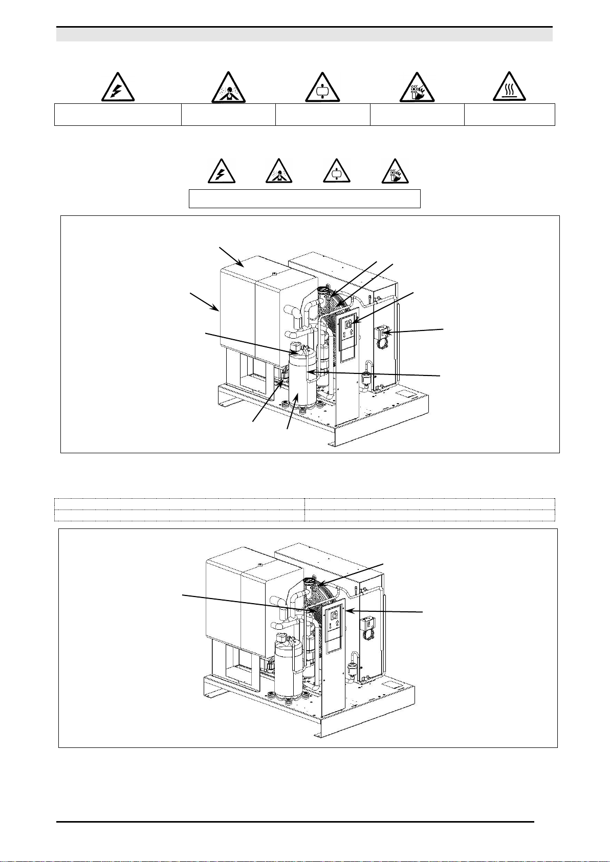
6.0 DANGER ZONES
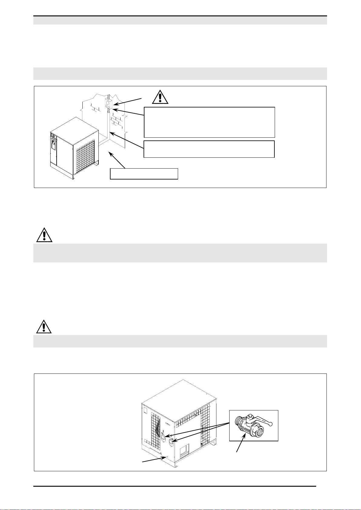
7.0 SAFETY DEVICES
8.0 POSITION OF PLATES
9.0 DRYERS ROOM
10.0 TRANSPORT AND HANDLING
11.0 UNPACKING
12.0 INSTALLATION
13.0 DIMENSIONS AND TECHNICAL DATA
14.0 MACHINE ILLUSTRATION
15.0 SCRAPPING THE DRYERS
PART B: INFORMATION RESERVED FOR TECHNICALLY SKILLED PERSONNEL
16.0 PARTIAL ROUTINE MAINTENANCE
17.0 TROUBLE-SHOOTING AND EMERGENCY REMEDIES
18.0 STARTING UP, FREE CONTACT FEATURES
ATTENTION: THERE IS A COPY OF THE WIRING DIAGRAM INSIDE THE ELECTRIC PANEL
ADDRESSES OF ASSISTANCE CENTRES
In the event of breakdown or malfunction of the dryer, switch it off and do not tamper with it. If repairs are needed, apply
only to a technical assistance centre approved by the manufacturer and insist on the use of original spare parts. Failure
to comply with the above may endanger the safety of the machine.
INTRODUCTION
Keep this manual with care for future consultation; the use and maintenance manual is an integral part on the
dryer. Read this manual carefully before carrying out any operations on the dryer.
The installation of the dryer and all operations involving it must be performed in conformity with the regulations
in force concerning electric plants and personal safety.
CHARACTERISTICS AND SAFETY PRECAUTIONS
BEFORE REMOVING THE PROTECTIVE GUARDS TO CARRY OUT ANY MAINTENANCE ON THE MACHINE, SWITCH OFF THE ELECTRIC
POWER SUPPLY AND DISCHARGE THE RESIDUAL PRESSURE INSIDE THE UNIT.
ALL WORK ON THE ELECTRIC PLANT, HOWEVER SLIGHT, MUST BE CARRIED OUT BY PROFESSIONALLY SKILLED PERSONNEL.
The manufacturer does not accept responsibility for damage caused as a result of negligence of failure to abide by the
instructions given above.
THIS MACHINE IS NOT SUITABLE FOR EXTERNAL INSTALLATION
THIS MACHINE CORRESPOND TO THE ESSENTIAL SAFETY REQUIREMENTS FORESEEN FROM THE
EUROPEAN STANDARD (2006/42 CE).
THE LUBRICATING LIQUIDS AND OTHER EVENTUAL FLUIDS MUST NOT BE DISCHARGED IN THE
ENVIRONMENT. THESE POLLUTING AND HAZARDOUS PRODUCTS MUST COMPULSORY BE DISPOSED BY
CHARGING AUTHORISED AND SPECIALISED FIRMS ACCORDING TO THE DIFFERENT TYPOLOGY OF
PRODUCT.
DIFFERENTIATE THE COMPRESSOR COMPONENTS ACCORDING TO THE DIFFERENT CONSTRUCTION
MATERIALS (PLASTIC, COPPER, IRON, OIL FILTER, AIR FILTER ECC…)