R2TECK DVLM-100 User manual

Digital Video Transmission System
DVLM-100
USER MANUAL
Wuxi R2TECK Co.,Ltd.

Wuxi R2TECK Co.,Ltd
Content
1. EASY WAY TO START THE DEVICE ........................................... 1
1.1 Operating steps and instructions ....................................................................................................... 1
1.1.1 Monitor ........................................................................................................................................ 1
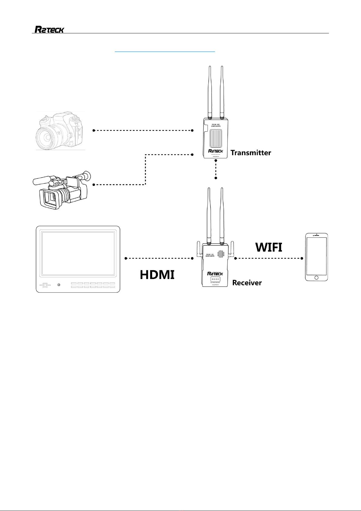
1.1.2 Transmitter ................................................................................................................................. 1
1.1.3 Receiver ..................................................................................................................................... 1
1.1.4 Mobile ......................................................................................................................................... 1
2. SPECIFICATION.......................................................... 3
3 INTRODUCTION .......................................................... 4
3.1 Disclaimer .............................................................................................................................................. 4
3.2 Profile ..................................................................................................................................................... 4
3.3 Intended usage ..................................................................................................................................... 4
3.4 Caution ................................................................................................................................................... 4
4. PRODUCT OVERVIEW..................................................... 6
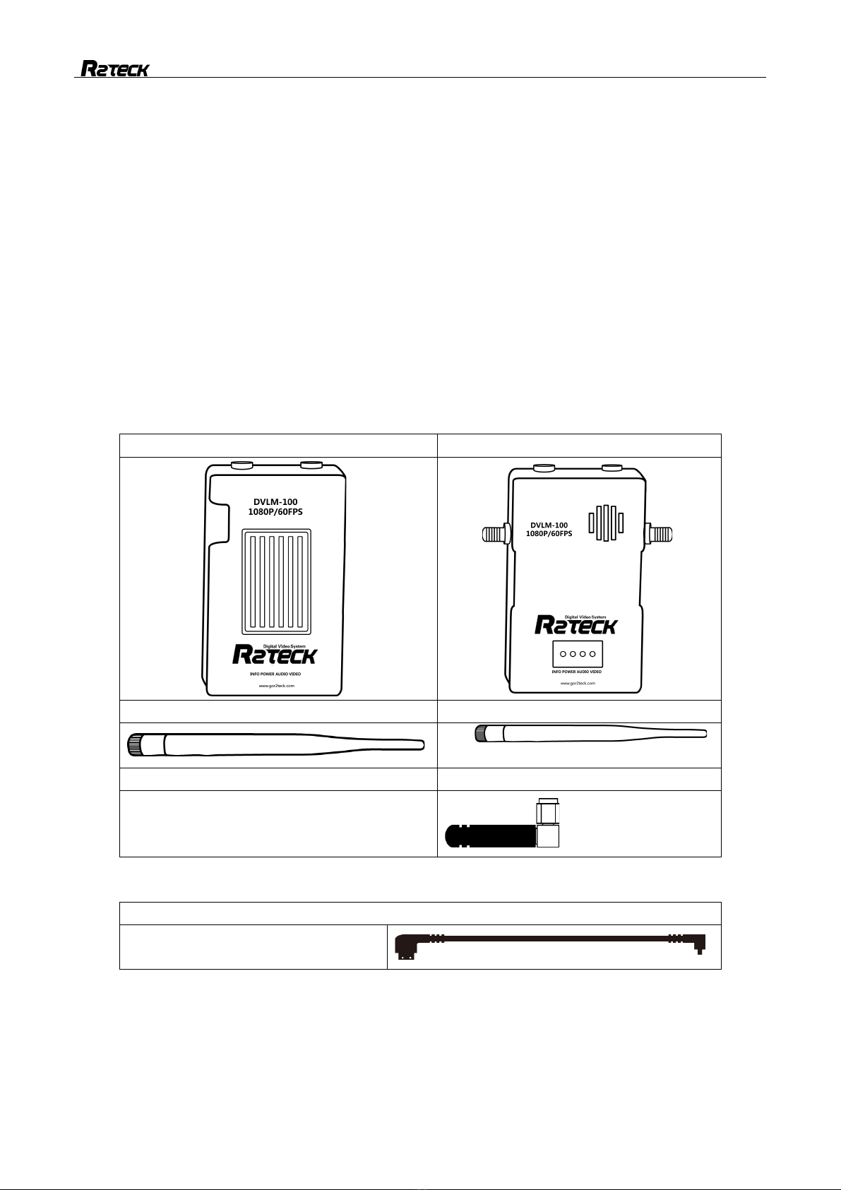
4.1 Brief introduction .................................................................................................................................. 6
4.2 Standard spec ....................................................................................................................................... 6
5. INTERFACE DEFINITION ................................................... 7
5.1 Transmitter port .................................................................................................................................... 7
5.2 Receiver port ....................................................................................................................................... 10
6. Installation ...................................................................................................................................... 12
6.1 Transmitter installation ...................................................................................................................... 12
6.2 Receiver installation ........................................................................................................................... 12
7. BIND AND FREQUENCY SWITCH............................................ 14
7.1 Frequency switch .................................................................................................................. 14
7.2 Bind ...................................................................................................................................................... 14
8. SOFTWARE UPGRADE INSTRUCTIONS .................................................................................... 15
8.1 Function description .............................................................................................................. 15
8.2 Operating steps ..................................................................................................................... 15
8.3 Display content ...................................................................................................................... 15
8.4 Trouble symptoms / solution ................................................................................................. 15
9. APP instruction ............................................................................................................................... 15
9.1 INFO setting ........................................................................................................................................ 16
9.2 Power setting ...................................................................................................................................... 16
10. TROUBLES SOLUTION .................................................. 17
10.1 Trouble symptoms / diagnosis / solution ............................................................................. 17
11. APPENDIX ............................................................ 18
11.1 Video input format requirement ...................................................................................................... 18
11.2 Monitor INFO content ...................................................................................................................... 18
12. CONTACT INFO ........................................................ 21

1
1. Easy way to start the device
1.1 Operating steps and instructions
1.1.1 Monitor
Ø Connect monitor to the power
1.1.1 Transmitter
Ø Install the antennas.
Ø Install the HDMI camera cable.
Ø Connect camera to the power, select the correct video format.
Ø Connect Transmitter to the power.
There should be below instructions if the Transmitter works well.
WORK light flash regularly.
HDMI light turn-on
LINK light turn-on if the Transmitter connect to Receiver.
1.1.2 Receiver
Ø Install the antennas
Ø Install the monitor by HDMI cable. (optional)
Ø Turn off the Receiver power button, then connect to the power (DC-12V power), turn on the receiver
power button again.
Ø Turn on the power.
There should be below instructions if the receiver works well.
WORK light flash regularly
HDMI light turn-on(if installed the HDMI monitor).
LINK light turn-on if the receiver connect to transmitter.
HDMI monitor instruction (if installed the HDMI monitor):
The monitor shows logo "R2TECK" after receiver connect to the power.
After that, the monitor shows progress bar: Start-up / Selfcheck / Link.
Monitor real-time display the camera video when the transmitter connect to the receiver.
1.1.3 Mobile
Ø The mobile connect the wifi network "R2TECK ", WIFI password "12345688"
Ø wait for connecting
Ø Run the APP (if the APP is already running, turn off it first then run again)
Ø The mobile real-time display the camera video, the MOBILE light on the receiver turn-on.
Attention: Currently only allow working one mobile, if want to change the mobile, please follow below process:
Disconnect the mobile with receiver wifi network.
Wait receiver MOBILE light turn off.
Repeat the above 4 steps.
iOS App installation: In App store, search the key word “DVLx” and download.

2
Android installation: Refer to http://www.gor2teck.com/download/ ->DVLX android mobile client (apply for
DVLM-100/DVL-1/DVL-C).
1.1.3.1

3
2. Specification
Here list the detailed specification about DVLM-100
Function specification
Communication distance
(outdoor, no obstruction)
100mw transmission distance ≥ 800m
800mw transmission distance ≥ 1500m
Wall Penetration ability
3 cement walls; 1 ferroconcrete wall
Output Power
25mw-800mw adjustable
Sensitivity
-95dbm±2dbm
Frequency
5G
Physics specification
working temperature
-10~60℃
storage temperature
-20~50℃
dimension (including the shell, not
including the antennas)
Transmitter: L.114mm x W. 70mm x H. 25mm
Receiver: L.127mm x W. 72mm x H. 28mm
Weight (including the shell, not
including the antennas)
Transmitter: 178g
Receiver: 233g
Hardware function support
Transmitter working voltage
DC-12V, 6V~17.1V, suggest the output power is more
than 2A
Receiver working voltage
DC-12V, 7V~22V, suggest the output power is more
than 2A

4
3 Introduction
3.1 Disclaimer
Thanks for purchasing the DVLM-100 from Wuxi R2TECK. Everyone need to read and understand
this disclaimer before using the DVLM-100. You are supposed to be accepted the disclaimer once the
product is started to use. Please comply with the installation and using process indicated in this use
manual. Wuxi R2TECK will not be responsible for the consequence of the improper use, improper install,
improper modify.
The product name, brand mentioned here are belong to R2TECK.
3.2 Profile
This use manual as the instruction of Full-HD Digital Video Transmission system DVLM-100, the
components and functions mentioned here may not be the standard spec. please check the enclosed list
with the product, please contact with the dealer if you have any question
The right of the manual write, modify and release only belong to Wuxi R2TECK, Without the
authorization of Wuxi R2TECK, this use manual could not be copied or modified or released
The information in this manual is only for DVLM-100 Full-HD Digital Video Transmission System.
This manual is subject to change without prior notice.
Version
profile code & version
release date
RR.H.0003. 0017. V01
2017.10
3.3 Intended usage
DVLM-100 use for wireless Full-HD Digital Video transmission
3.4 Caution
The effectiveness of the use product is subject to if comply with operate and maintain
direction in this manual.
Before start the product, the staff must make sure the operate process and condition is
correct. specially to check the product cables are good or not, if the cable is damaged,
please change it before start the product.

5
DVM-100 is intended to use on the film and other Full-HD digital video transmission.
DVLM-1 may not be reached the defined function if it works in the improper temperature,
improper humidity and improver air pressure.
DVLM-100 should not work when it is wet. Have to make sure it is dry when you use it.
DVLM-100 is the high precise product, it is forbid to beat and clash.
Product life time is 2 years, quality warranty is 1 year.
Manufacture and dealer are responsible for the product maintenance, without the
authorization, please don't fix the product and don't modify the product.

6
4. Product overview
4.1 Brief introduction
DVLM-100 is the 1080p full-HD Digital Video transmission system which including transmitter and
receiver, it transmit the video, audio, image and more information by the wireless communication mode.
DVLM-100 is perfect for all fields video transmission because of the light weight, low power, long distance,
low latency.
4.2 Standard spec
4.2.1 product main part
Transmitter x 1
Receiver x 1
Transmitter antenna x 2
Receiver antenna x 2
Receiver mobile antenna x 2
4.2.2 Transmitter cable
HDMI cable (D-D) x 1
Camera HDMI cable

7
4.2.3 Receiver cable
Hot shoes
5. Port definition
5.1 Transmitter port
5.1.1 Back side
5.1.1.1
[1]: For frequency switch setting
Press the button more than 5 seconds, 3 lights (HDMI, LINK, WORK) are all turn-off, release the
key, 3 lights flash as 0.5Hz frequency, and then 3 lights back to normal state, that means
channel change is finished. If devices not connected yet after 10 seconds of frequency switch
process, please switch again. The frequency supported by device as below:
5180
5220
5260
5320
5520
5540
5560
5580
5600
5620
5640
5660
5680
5700
[2]: For bind the Transmitter and receiver.
Press the button more than 5 seconds, 3 lights (HDMI, LINK, WORK) are all turn-off, then 3
lights flash one by one, when the LED light works well that means they are well bind. This may
takes 2 minutes. If the connection has not been resumed after 2 minutes, repower on both ends,
and don’t need rebind.

8
5.1.2 Right side port
5.1.2.1
HDMI port: for connecting with the camera.
Power port: Power button.
Work light: for monitoring the Transmitter working status.
Light status
Description
Action
Flash
regularly
Transmitter works well
NA
other status
Transmitter does not work
Connect the system to the
power again, or contact with
the customer service.
Link light, for monitoring the status of connect with the receiver.
Light status
Description
Action
Turn-on
Connect with receiver well
NA
Turn-off
Does not connect with receiver
1. Please wait for connecting
2. Make sure the receiver is
connected the power.
3. Bind the Transmitter and
receiver again
4. Connect the power again
HDMI light, for monitoring the camera status.
Light status
Description
Action
Turn-on
Camera connect well
NA
Turn-off
Camera does not connect
check camera cable position
Flash
Camera output format is not
correct
check camera output format
setting

9
5.1.3 Left side port
5.1.3.1
DC-12V port: 12V-DC power.
5.1.4 Front side port
5.1.4.1
Cooling fan: Pay attention to not cover the cooling fan.

10
5.2 Receiver port
5.2.1 Left side port
5.2.1.1
[1]:For frequency switch setting
Press the button more than 5 seconds, 4 lights (HDMI, LINK, WORK, MOBILE) are all turn-off,
release the key, 4 lights flash as 0.5Hz frequency, and then 4 lights back to normal state, that
means channel change is finished. If devices not connected yet after 10 seconds of frequency
switch process, please switch again. The frequency supported by device as below:
[2]:For bind the air part and ground part.
Press the button more than 5 seconds, 4 lights (HDMI, LINK, WORK, MOBILE) are all turn-off,
then stop press the button, 4 lights flash one by one, when the LED light works well that means
they are well binded.This may takes 2 minutes.If the connection has not been resumed after 2
minutes, repower on both ends, and do not need to rebind.
[3]: Monitor the receiver work status.
Light status
Description
Action
Flash
regularly
Receiver works well
NA
Other status
Receiver does not work well
Connect the power again or
contact with the customer
service
[4]: Monitor Transmitter and receiver connect status.
Light status
Description
Action
Turn-on
Connect with Transmitter
NA
Turn-off
Des not connect with Transmitter
1. Please wait for connecting
2. Make sure the Transmitter
is connecting the power.
3. Bind the Transmitter and
receiver again.
4. Connect the power again
[5]: monitor the display device status.
Light status
Description
Action
Turn-on
Display device connect well
NA
Turn-off
Display device does not connect
Check Display device cable

11
position
[6]: Monitor mobile connect status.
Light status
Description
Action
Turn-on
Mobile connect well
NA
Turn-off
No mobile connect
Make sure the mobile connect
with the network, turn off the
software then turn on again.
5.2.3 Right side port
5.2.3.1
[1]: DC-12V power button
[2]: HDMI port, for connect with the monitor.
[3]: USB port, software upgrade.
5.2.4 Front side port
5.2.4.1
Air vent: Pay attention to not cover the air vent.
[1]: INFO port, for specification display.
[2]: Power port, for switch signal reception sensitivity.
[3]: For audio button.
[4]:Video port, for switch the picture quality, have 3 level for choose.

12
6. Installation
6.1 Transmitter installation
6.1.1 Antenna installation
Tak e ou t tw o pc s Transmitter antenna and fix them on the transmitter.
6.1.2 HDMI cable installation
One end of cable connect to the camera, another end of cable connect to the Transmitter.
6.1.3 power cable installation
Both of DC and AC power are supported by the receiver.
Support Sony NP-F970/770 battery.
Support DC-12V power, suggest the output power is more than 2A.
Connect to the power according to the requirement.
6.2 Receiver installation
6.2.1 Antennas installation
Prepared 4pcs receiver antennas, 2pcs of each style, fix them on the receiver according the photo
below:
Attention:
The receiver antenna is not a full direction antenna ,
For better transmit result, please make sure the antennas perpendicular to the ground.
Please operate refer to blow pictures .

13
6.2.1.1
6.2.2 HDMI cable installation
One end of HDMI connect to the monitor, another end of HDMI connect to the receiver.
6.2.3 Power cable installation
Both of DC and AC power are supported by the receiver.
Support Sony NP-F970 battery
Support 12V-DC power, suggest the output power is more than 2A.
Connect to the power according to the requirement. Suggest use AC power.
6.2.4 Mobile APP installation
iOS App installation: In App store, search the key word “DVLx” and download.
Android installation: Refer to http://www.gor2teck.com/download/ ->DVLX android mobile client
(apply for DVLM-100/DVL-1/DVL-C).

14
7. Bind and Frequency switch
7.1 Frequency switch
This feature is implemented at the transmitter or receiver, there is not required to implemented it at
the same time. Please make sure the transmitter and receiver connection status is well when
implemented at the receiver.
For channel switch setting
Transmitter: Press the button more than 5 seconds, 3 lights (HDMI, LINK, WORK) are all turn-off,
release the key, 3 lights flash as 0.5Hz frequency, and then 4 lights back to normal state, that means
channel change is finished.
Receiver: Press the button more than 5 seconds, 4 lights (HDMI, LINK, MOBILE, WORK) are all
turn-off, release the key, 4 lights flash as 0.5Hz frequency, and then 4 lights back to normal state, that
means channel change is finished.
7.2 Bind
Function explanation: bind function bind one Transmitter with one receiver.
Process: the device LED light shows correctly, press two BIND buttons on Transmitter and receiver
together and keep more than 5 seconds, all the LED light turn off, release the button. All the LED light
flash one by one regularly, means the device start the bind progress. when all the LED lights of both side
shows correctly that means bind progress is finished.
Attention:
When the Transmitter is connecting with the receiver, the video will be paused two times during the
bind progress, the video will work correctly when the progress is finished.
One Transmitter only work together with the bind receiver after processed the bind function. Bind
progress should be worked on the Transmitter and receiver at same time, please turn off other devices
during bind progress in order to avoid mismatching errors.
All the buttons on the Transmitter and receiver will be worked after the device started 30 seconds
later, the LED lights flash high speed means the buttons are not available now.

15
8. Software upgrade instructions
8.1 Function description
This feature is software upgraded at transmitter and receiver. Please make sure the transmitter and
receiver connection status is well which have display transmission/ work light flash/ link light flash.
8.2 Operating steps
Ø Prepare 1Set of DVLM-100 video transmission system.
Ø 1PC of monitor for monitoring the processes.
Ø Prepare 1 PC of U-disk which is FAT32 format.
Ø Copy the software upgrade package (uograde.des3) which is provided by R2TECK to U-disk
Ø Connect the monitor with Receiver and charge the monitor.
Ø Connect the U-disk with USB port.
Ø Charge the Transmitter.
Ø Charge the Receiver.
Ø The receiver will be in the process of Auto upgrade.
Ø The device will work normally after 10 seconds when software upgrade is successfully conducted.
Ø Remove the U-disk.
8.3 Display content
Ø Display the boot logo.
Ø Display the system upgrade interface logo.
Ø Display the upgrade processes.
Ø Display the upgrade completed.
Ø Display the video on the monitor.
8.4 Trouble symptoms / solution
Interface
Description
Action
Couldn’t link the upgrade
interface
No upgrade package
Copy the software upgrade
package to U-disk.
Process:U-Disk Err,
Please Format to FAT32。
U-disk format is
incorrect
Formatting the U-disk into FAT32
format.
Process:Failed
Upgrade failed
Upgrade again.
Copy the upgrade package and
upgrade again.
If the above solutions do not work,
please contact with the customer
service.
Attention: The device will detect whether the U disk is assembled at startup. If the U disk is installed, the
device will automatically upgrade. In order to ensure the normal use of the device, please remove the U
disk after upgrading, and avoid unnecessary upgrade at the next start.
For upgrade successful, please power the transmitter and receiver.

16
9. APP instruction
9.1 INFO setting
Click OSD button, select "Turn-on" or "Turn off", match to the "Display" or "Not display"
8.1.1
9.2 Power setting
Click "setting" button to adjust the power, if click 100mw, then the video top right corner shows "PW:
100 OK", means output power setting is succeed.
8.2.1

17
10. Troubles solution
Below is the device maintenances about DVLM-100, to help the users whom don't have professional
testing equipments and technology to solve the simply troubles.
10.1 Trouble symptoms / diagnosis / solution
Symptoms
Diagnosis
Solution
No video
Did not follow the process
Follow the process as chapter
1.Confirm the power process is correct.
Transmitter
HDMI light flash
1. video format does not correct, check
if the camera is supported by
DVLM-100 and select the correct video
format, the camera list as appendix
2. Camera HDMI cable bad contacted,
connect the HDMI cable again.
HDMI light turn-off
Camera HDMI cable is bad contacted,
connect the HDMI cable again.
WORK light is
abnormal (not flash
regularly)
Connect the power again.
LINK light turn-off
Connect the power again
Receiver
HDMI light turn-off
Camera HDMI cable is bad contacted,
connect the HDMI cable again.
WORK light is
abnormal (not flash
regularly)
Connect the power again.
LINK light turn-off
Connect the power again.
Bind
abnormal
LINK light turn-off
If the above solutions do not work,
please restore factory setting
Restore factory setting succeed,
suggest to process the bind progress.
Action and instruction as chapter 7
Blue screen
Transmitter HDMI bad contact
Please make sure HDMI cable works
and connect with the device well.
Video pause
HDMI cable problem
Change a new HDMI cable
Out of allowed distance
Back to the allowed distance
If the above solutions do not work, please contact with the customer service.

18
11. Appendix
11.1 Video input/Output format requirement
Video input/ format requirement
Signal
type
Video
format
Video Input Resolution
Remark
HDMI
PAL,
NTSC
1080p@60/50/30/25/24fps;
1080i@60/50fps;
720p@60/50/30/25/24fps;
IF want to change the
resolution, you have to
re-start the both of the
Transmitter and receiver.
Video Output format requirement
Signal type
Video
output
format
Video Output Resolution
Remark
HDMI
PAL,
NTSC
1080p@60/50/30/25/24fps;
1080i@60/50fps;
720p@60/50/30/25/24fps;
IF want to change the
resolution, you have to
re-start the both of the
Transmitter and receiver.
11.2 Monitor INFO content
Beside the video, on the top side and bottom side of the monitor display the OSD data.
:Video signal intensity
:Transmitter power voltage
POWER:Transmitting power
:Current frequency
:Receiver power voltage
:Current Picture Quality
:Audio button state
Table of contents
Other R2TECK Extender manuals