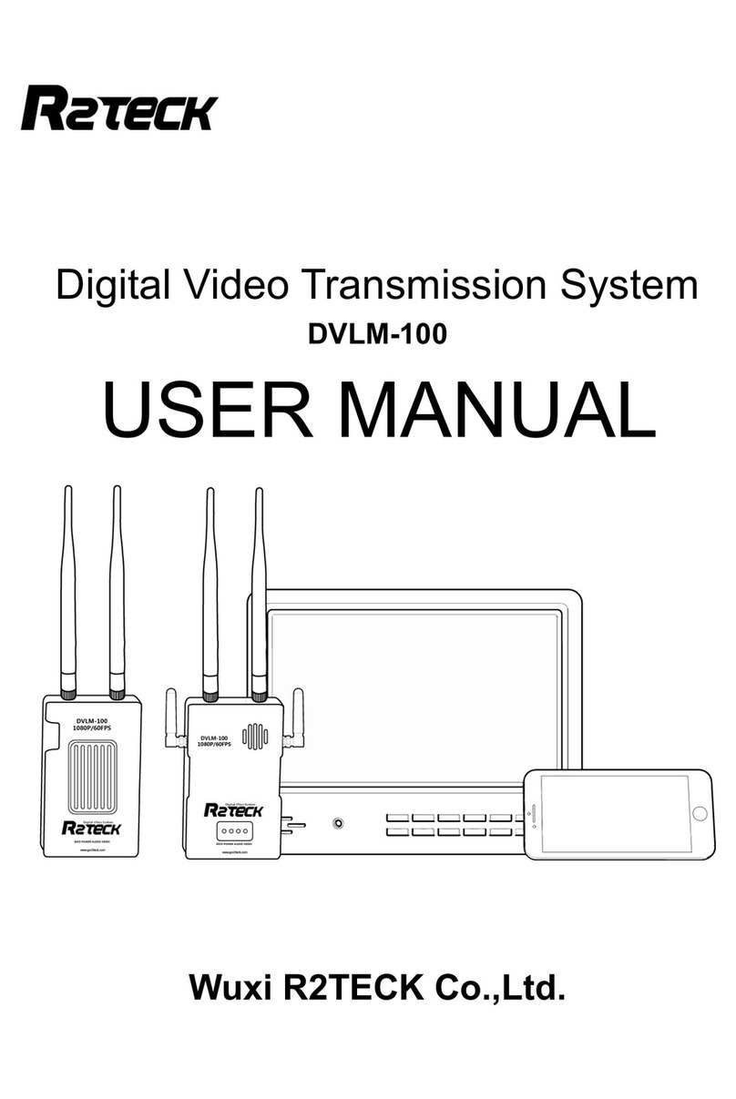
R2TECK DVLC User manual

Digital Video TransmissionSystem
DVLC
USER MANUAL
Wuxi R2TECKCo.,Ltd.

锡人人行拍网络科技有限公司
Content
1. Easywaytostart thedevice...................................................................................1
1.1Operatingstepsandinstructions...................................................................1
2. Specification............................................................................................................ 3
3. Introduction.............................................................................................................4
3.1Disclaimer......................................................................................................4
3.2Profile.............................................................................................................4
3.3Intended usage..............................................................................................4
3.4Caution..........................................................................................................4
4. Productoverview....................................................................................................6
4.1Brief introduction............................................................................................6
4.2Standardspec................................................................................................6
5. Portdefinition..........................................................................................................8
5.1Air systemport...............................................................................................8
5.2Groundsystemport.....................................................................................11
6. Installation............................................................................................................. 14
6.1Air systeminstallation..................................................................................14
6.2Groundsysteminstallation...........................................................................14
7. Bind....................................................................................................................... 16
8.Troublessolution................................................................................................... 17
8.1Troublesymptoms/ diagnosis/solution......................................................17
9. Appendix............................................................................................................... 19
9.1MonitorOSDcontent...................................................................................19
10. Contact info......................................................................................................... 20

锡人人行拍网络科技有限公司
1
1. Easywaytostart thedevice
1.1Operating stepsand instructions
1.1.1Airsystem
ØInstall the antennas.
ØInstall the MIPI camera.
ØInstall the OSDcable(optional).
ØInstall the TF card(Support 4GB-64GB, FAT32 format), optional.
ØConnect air systemtothe power.
Thereshouldbebelow instructions if the air systemworkswell.
POWERlightturn-on.
CAMlight turn-on.
REClight turn-on ifthe proper TF cardhas been inserted, and the recordingfunction isturnedon.
LINK light turn-on ifthe air systemconnect togroundsystem.
1.1.2Ground system
ØInstall the antennas.
ØInstall the monitor byHDMI cable. (optional)
ØTurnoff thegroundsystempower button, then connect tothe power (batteryof12V-DC power), turn
on the ground systempower button again.
ØTurnon the power.
Thereshouldbebelow instructions if the ground systemworks well.
After 15seconds ofpower on, the WORKlight willdisplaythe breathingeffect, and the WORKlight will
loopfromontooffon display.
HDMI light turn-on(ifinstalled the HDMI monitor).
LINK light turn-on ifthe air systemconnect toair system.
HDMI monitorinstruction (if installed the HDMI monitor).
The monitor showslogo "R2TECK"after ground systemconnect tothe power.
After that, the monitor showsprogress bar: Start-up / Selfcheck/ Link.
Monitor real-timedisplaythe cameravideo andOSDinformation(ifOSDmodulehas been
assembled)when theair systemconnect tothe ground system.
1.1.3Mobile
ØThe mobileconnect the WIFI networkwhose nameisthe sameas the device number, WIFI
passwordis"12345688".
ØWait for connecting.
ØRun theAPP(ifthe APPisalreadyrunning, turnoffit first then runagain).
ØThe mobilereal-timedisplaythe cameravideo, the MOBILElight on the ground systemturn-on.

锡人人行拍网络科技有限公司
2
Attention:Currentlyonlyallowworking onemobile, if want tochangethemobile, please follow
belowprocess:
Disconnect the mobilewithgroundsystemwifi network.
Wait ground systemMOBILElight turnoff.
Repeat the above4steps.
IOSApp installation: InAppstore, search the keyword r2teck”and download.
Figure1.1.3.1Connectiondiagram
Attention:Whenusedthegroundsystemisfixedon theground,itsnotaportabledevice.

锡人人行拍网络科技有限公司
3
2. Specification
Herelist the detailed specification about DVLC, as showninTable2.1.1.
Table2.1.1List ofParameters
Performance Parameter
Communication distance
(outdoor, no obstruction)
100mw ground distance ≥800m
500mw ground distance ≥3000m(doubledistanceinair)
Ifchange tothe wide angeldirectionalpatch antenna,the
distance will bedouble.
EffectiveRadiated Power(EIRP)
25mw~800mw adjustable
Receivingsensitivity -95dbm±2dbm
Operatingfrequency 5200MHz
Physical Parameter
OperatingTemperature -10~60
StorageTemperature -20~50
Size(Include shell, no antenna) Air system: L.71mm×W.51mm×H.19 mm
Ground system: L.105 mm ×W.74 mm ×H.26 mm
Weight(Includeshell,no
antenna) Air system: 70g
Ground system: 174g
Hardwarefunctionsupport
Air systemOperating Voltage DC-12V,Compatiblewith2S~3S,averagepower
consumption 5W,Max power consumption12W
Ground systemOperatingvoltage
DC-12V,Compatiblewith2S~3S,averagepower
consumption 5W,Max power consumption12W

锡人人行拍网络科技有限公司
4
3. Introduction
3.1Disclaimer
Thanksfor purchasing theDVLCfromWuxiR2TECK. Everyone need toreadand understandthis
disclaimer beforeusing theDVL1. You aresupposedtobe accepted the disclaimer once the product is
started touse. Pleasecomplywiththe installationand using process indicatedinthisuse manual.Wuxi
R2TECKwillnot be responsiblefor the consequenceofthe improper use, improper install, improper
modify.
The product name, brand mentioned herearebelongtoR2TECK.
3.2Profile
Thisusermanualas the instructionofFull-HD DigitalVideoTransmission systemDVLC, the
componentsand functionsmentioned heremaynot be the standardspec. please checkthe enclosed list
withthe product, pleasecontact withthe dealer ifyou haveanyquestion.
The right ofthe manualwrite, modifyand releaseonlybelong toWuxiR2TECK, Without the
authorization ofWuxiR2TECK, thisuse manualcouldnot be copied ormodified or released
The information inthismanualisonlyfor DVLCFull-HDDigitalVideo TransmissionSystem.
Thismanualissubject tochange without prior notice.
Version
profilecode&version release date
RR.H.0001. 0018. V01 August 2018
3.3Intendedusage
DVLCuse for wireless Full-HDDigitalVideo transmission.
3.4Caution
The effectiveness ofDVLCuse issubject toif complywithoperateand maintaindirectionin
thismanual.
Beforeoperatingthe product, the staff mustmake surethe operateprocess and conditionis
correct. speciallytocheckthe product cablesaregood or not, if the cableisdamaged,
please changeit beforeoperatingthe product.

锡人人行拍网络科技有限公司
5
DVLCisintended touse onthe UAV andother Full-HDdigitalvideo transmission. DVLC
maynot be reachedthe definedfunctionifit worksinthe improper temperature, improper
humidityand improver air pressure.
DVLCshouldnot workwhen it iswet. Havetomakesureit isdrywhen you use it.It should
be driedimmediatelyat aventilated place incase of accidentallywet.
DVLCisthe high precise product. NOBEATING, CLASHING ORKNOCKING.
Product lifetimeis2years, qualitywarrantyis1year.
Manufactureand dealer areresponsiblefor the product maintenance, without the
authorization, please don'tfixthe product anddon't modifythe product.

锡人人行拍网络科技有限公司
4. Product overview
4.1Briefintroduction
DVLCisthe 1080p full-
HD DigitalVideo transmissionsystemwhichincluding air
it transmit the video, imageand moreinformation bythe wirelesscommunication mode.DVL
for allfields video transmissionbecauseofthe light weight, low power, long distance, low latency. Please
install the air system
onthe aircraft, connect the ground systemtothe monitoror mobilephone to
monitoring the video.
4.2Standardspec
4.2.1Product mainpart
Air systemx1
Camerax1
6
4. Product overview
HD DigitalVideo transmissionsystemwhichincluding air
part and ground part,
it transmit the video, imageand moreinformation bythe wirelesscommunication mode.DVL
for allfields video transmissionbecauseofthe light weight, low power, long distance, low latency. Please
onthe aircraft, connect the ground systemtothe monitoror mobilephone to
Ground systemx1
Ground systemantenna x2
Ground systemmobileantenna
x2
part and ground part,
it transmit the video, imageand moreinformation bythe wirelesscommunication mode.DVL
Cisperfect
for allfields video transmissionbecauseofthe light weight, low power, long distance, low latency. Please
onthe aircraft, connect the ground systemtothe monitoror mobilephone to
x2

锡人人行拍网络科技有限公司
4.2.2Airsystemcable
Air systempower cablex1(standard)
Air systempower cable12V
4.2.3Ground systemcable
Power adapter x1(optional)
Vehiclepower12V-
DCforground
system
HDMI cablex1(optional)
MonitorHDMI cabe
Monitor x1(optional)
For video receiveandmonitoring
Ground systemtripod x1(optional)
Ground systemtripod
Extensiontripod x1(standard)
Extensionbar
Batterybinx1
Directlycharging the ground system
inbatterybin..
7
Air systempower cablex1(standard)
DCforground
For video receiveandmonitoring
Ground systemtripod x1(optional)
Directlycharging the ground system

锡人人行拍网络科技有限公司
8
5. Port definition
5.1Air system port
5.1.1Back side
Figure5.1.1.1schematicdiagramofback side
[1]:REClight,mp4videorecording statuslight
Light status
Description
Operation
Turn-on The recordingfunction ison
and the recording statusis
normal. NA
Turn-off The recording function isoff. NA
Flashing The recordingfunction ison
and the recording stateis
abnormal.
Checkwhetherthe TF card
has beeninserted,orturnoff
the recording functiontoggle
switch toreopen.
[2]:CAMlight,Thecameraisconnectedand thestatusof appropriateimagedatacollection.
Light status Description Operation
Turn-on The cameraisconnectedand
the image datacollectionis
normal. NA
Turn-off The cameraisnot connected.
Replugthe cameracable.
[3]:LINKlight, Indicatethewirelessconnectionstatuswiththegroundsystem.
Light status Description Operation
Turn-on The wireless moduleis
connected tothe ground
system. NA
Turn-off The wireless moduleisnot1. Please wait for connecting;

锡人人行拍网络科技有限公司
9
connected tothe ground
system. 2.Makesurethe airsystemis
connected the power;
3.Bind the airsystemand
groundsystemagain;
4. Connect the power again.
[4]:POWERlight, Indicatethepowersupplystateof theairsystem, and thedescriptionof
eachstateisas follows.
Light status Description Operation
Turn-on Nopower supply. Checkwhetherthe power
supplyisnormal.
Turn-off The power supplyisnormal. NA
[5]:BINDbutton,Forbindtheairsystemand groundsystem.
Press the button morethan5seconds, 3lights(REC, CAM, LINK) areallturn-off, then 3lights
flash one byone, when theLEDlight workswell that meanstheyarewell bind.
[6]:FREQ-SWbutton,Reserved,Not support temporary.
[7]:STOP/RECvideorecordingtoggleswitch
mp4formatvideo recordingtoggleswitch:turnoffthe recording functionbytoggling left(STOP),
then the recordinglight ofvideo turnoff; turnon the recording function bytogglingright (REC),
which lightsup/flashes the recording light.
[8]:TF-CARD slot
5.1.2Left sideport
Figure5.1.2.1Schematic diagramofleft side port
[1]: MIPI cameraport,Connect withMIPI camera, andget video dataofthe cameraviathisport.

锡人人行拍网络科技有限公司
10
[2]: OSD port,When it isnecessarytodisplaythe OSD information ofthe flight controlsystem, connect to
the dataline port ofthe flight controlsystemfor readingOSDinformation.
5.1.3Right sideport
Figure5.1.3.1Schematic diagramofright side port
[1]: OSD port,When it isnecessarytodisplaythe OSD information ofthe flight controlsystem, connect to
the dataline port ofthe flight controlsystemfor readingOSDinformation.
[2]: POWERport,For air systemget the powerDC-12Vor 2S~3Sfromthe aircraft.
5.1.4Topsideport
Figure5.1.4.1Schematic diagramoftop side port
[1]: 1080p /720p toggleswitch,Toggleleft to1080pand right to720p.
1080P/720P

锡人人行拍网络科技有限公司
11
5.2Ground systemport
5.2.1Bottomsideport
Figure5.2.1.1schematicdiagramofbottomside port
[1]: Batteryport, For connect with2S/3Sbattery.
[2]: Fixhole, For fixthe ground systemon the tripod.
[3]: DC power port, For ground systemtoconnect withthe DCpower, suggestoutput power is
morethan 1A.
5.2.2Left sideport
Figure5.2.1.1schematicdiagramofleft side port
[1]: Bind button,For bind the air systemand groundsystem.
Press the button morethan5seconds, 4lights(HDMI, LINK, OSD,WORK) areall turn-off, then 4lights
flash one byone, when theLEDlight workswell that meanstheyarewell bind.
[2]: Worklight,For monitor the ground systemworkingstatus.
Light status Description Action
Flash regularly The ground systemworks
well. NA

锡人人行拍网络科技有限公司
Other status
The ground systemdoesnot
work.
[3]:Linklight,For
monitor the status ofconnect withthe
Light status
Description
Turn-on
Connect with
Turn-off
Doesnotconnectwith
system
[4]: HDMI light,F
ormonitor the camerastatus.
Light status
Description
Turn-on
Cameraconnect well.
Turn-off
Cameradoesnot connect.
[5]: MOBILElight,
Formonitor the status ofconnectwiththe mobile
Light status
Description
Turn-on
Connectwithmobile
well.
Turn-off
Doesnotconnectwith
device.
5.2.3Right sideport
Figure5.2.3.1schematicdiagramofright side port
[1]: Power button, ON(the systemconnect the
[2]: HDMI port, F
or connect withthe monitor.
[3]: USB port, For firmwareUpdate.
12
The ground systemdoesnot
Connectthe systemtothe
poweragain,orcontactwith
the customer service.
monitor the status ofconnect withthe
air system.
Description
Action
Connect with
air systemwell NA
Doesnotconnectwith
air
1. Please wait for connecting
2.Makesurethe ground
systemis
connectedthe
power;
3.Bindthe airsystemand
groundsystemagain;
4. Connect the power again
ormonitor the camerastatus.
Description
Action
Cameraconnect well.
NA
Cameradoesnot connect.
Check
cameracableposition.
Formonitor the status ofconnectwiththe mobile
device(iPhone、
iPad).
Description
Action
Connectwithmobile
device NA
Doesnotconnectwith
mobile
Makesurethatthe mobile
device isconnectedtothe
groundsystem
network.Close
the background softwareand
reopenit.
Figure5.2.3.1schematicdiagramofright side port
[1]: Power button, ON(the systemconnect the
power), OFF (the systemwithout the power)
or connect withthe monitor.
Connectthe systemtothe
poweragain,orcontactwith
1. Please wait for connecting
;
2.Makesurethe ground
connectedthe
3.Bindthe airsystemand
4. Connect the power again
.
cameracableposition.
iPad).
Makesurethatthe mobile
device isconnectedtothe
network.Close
the background softwareand
power), OFF (the systemwithout the power)

锡人人行拍网络科技有限公司
5.2.4Front side port
Figure5.2.4.1schematicdiagramoffrontside port
[1]:
Air vent: Payattentiontonot cover the
13
Figure5.2.4.1schematicdiagramoffrontside port
Air vent: Payattentiontonot cover the
air vent.

锡人人行拍网络科技有限公司
14
6. Installation
6.1Air system installation
6.1.1Antennainstallation
ØTakeout twopcs air systemantenna.
ØInstall themon the airsystemantenna holes,when you hearaclicking soundindicates completion of
installation.
Attention:Forbettertransmit result, please makesuretheantennabeawayfromthemetal and
carbon fiberframe, avoidbeingblockedbythemainbodyof theaircraft orbatteries, antenna
shouldbevertical totheground.
Figure6.1.1.1schematicdiagramofairsystemantenna installation
6.1.2MIPI camerainstallation
Connect oneend ofthe MIPI cabletothe cameraandthe other end tothe MIPI port ofthe air system.
6.1.3Powercableinstallation
one end withterminalsofthe cableconnect withair systempower port, another end ofcableconnect
withpower 12V-DC, the red cableispositive, the blackisnegative.
6.2Ground systeminstallation
6.2.1Antennas installation
Prepared4pcs groundsystemantennas, 2pcs ofeach style, fixthemon the groundsystemaccording
the photobelow:

锡人人行拍网络科技有限公司
Figure6.2.1.1
schematicdiagramofground systemantennainstallation
6.2.2HDMI cableinstallation
One end ofHDMI connect tothe monitor, the other end ofHDMI connect tothe groundsystem.
6.2.3Powercableinstallation
BothofDCandACpoweraresupportedbythe ground system.
Support 2s-3s modelbattery
Support 12V-DCpower,
suggest th
Connect tothe power accordingtothe requirement.
15
schematicdiagramofground systemantennainstallation
One end ofHDMI connect tothe monitor, the other end ofHDMI connect tothe groundsystem.
BothofDCandACpoweraresupportedbythe ground system.
suggest th
eoutput power ismorethan 1A.
Connect tothe power accordingtothe requirement.
One end ofHDMI connect tothe monitor, the other end ofHDMI connect tothe groundsystem.

锡人人行拍网络科技有限公司
16
7. Bind
Function description:Restores the device tofactorysettings,bind one airsystemwithoneground system
and gives the pairthematchingIDcode.
Operationmethod: the device LEDlight showscorrectly, press twoBINDbuttons on air systemand
groundsystemtogether and keepmorethan 5seconds, allthe LEDlight turnoff, release the button. All
the LEDlightflash onebyone regularly,means the device start the bind progress.when allthe LEDlights
ofbothsides showscorrectlythat meansbindprogress isfinished.
Attention:Whenthe air systemisconnecting withthe groundsystem, the video willbe paused two
times during the bindprogress, the video will workcorrectlywhen the progressisfinished.

锡人人行拍网络科技有限公司
17
8. Troubles solution
Below isthe device maintenances about DVLC, tohelpthe userswhomdon't haveprofessional
testing device andtechnologytosolvethe simplytroubles.
8.1Troublesymptoms /diagnosis/ solution
Table8.1.1Troublediagnosisandsolution
Symptoms Diagnosis Solution
Novideo
Didnot follow the process Follow the process aschapter 1.
Air system
REClight
flash
Insert the TF cardfirstand turnon the video
recording function.Ifyou haveinserted the
TF card,you need toturnoffthe video
recording function and open itagain.Make
surethe TFcardformat isFAT32.
CAMlight
turn-off
MIPIcableisbadcontacted,connectthe
MIPI cableagain.
POWERlight
turn-off
Batteryisdead.Replacethe batteryand
connect the power again.
LINK light
turn-off Connect the power again.
Ground
system
HDMI light
turn-off
CameraHDMI cableisbad connected,
connect the HDMI cableagain.
WORKlightis
abnormal(not
flash
regularly)
Connect the power again.
LINK light
turn-off Connect the power again.
Bind
abnormal
LINK light
turn-off
Ifthe abovesolutions donotwork,please
restorefactorysetting
Restorefactorysetting succeed,suggestto
processthe bind progress.
Actionand instruction aschapter 7.
Blue screen
Airsystem
HDMI bad
contact
Pleasemake sureHDMIcableworks and
connect withthe device well.

锡人人行拍网络科技有限公司
18
Video pause
HDMI cable
problem Change anew HDMI cable.
Outof
allowed
distance
Backtothe allowed distance.
OSD display
abnormal OSD cableisbad connected.ReconnectOSD cableofthe ground system.
Flightcontrol
batteryvoltage
VT not accurate
Power supplyisuncalibrated. Calibratethe flightcontrolpowervoltage in
the groundstation softwareinadvance.
If theabovesolutionsdonotwork, pleasecontactwiththecustomerservice.
Other manuals for DVLC
1
Table of contents
Other R2TECK Extender manuals