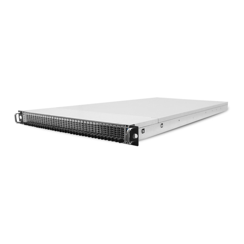
Rackable Systems OmniStor 4900F Series User manual


Rackable Systems Inc.
Restricted Rights and Liability
No part of this manual may be reproduced, stored in a retrieval system, or transmitted, in any form or by any means, electronic,
mechanical, recording, or otherwise, in whole or part, without prior written permission from Rackable Systems Inc.
Rackable Systems Inc. shall not be liable for any damages or for the loss of any information resulting from the performance or use of the
information contained herein. Your rights to the software are governed by the license agreement included with any accompanying
software. Information in this manual is subject to change without notice. Product features and specifications described are subject to
change without notice.
Copyright © 2005 Rackable Systems Inc. All Rights Reserved.
Rackable Systems Inc.
1933 Milmont Ave.
Milpitas, CA 95035
http://www..rackable.com
Rackable Systems, and OmniStor are trademarks of Rackable Systems Inc.
The names of actual companies and products mentioned herein may be the trademarks of their respective owners.
Agency Notes
WARNING: Drives and controller/adapter cards described in this manual should only be installed in UL-listed and CSA certified computers that give
specific instructions on the installation and removal of accessory cards (refer to your computer installation manual for proper
instructions).
ATTENTION: Les lecteurs et cartes contrôleurs décrits ici ne doivent être montés que sur des ordinateurs homologués (UL et CSA) et livrés avec des
manuels contenant les instructions d’installation et de retrait des accessoires. Reportez-vous au manuel d’installation de votre ordinateur.
SERVICE NOTE: Remove the power cables prior to servicing this equipment.
!


i
Contents
About this Manual . . . . . . . . . . . . . . . . . . . . . . . . . . . . . . . v
Welcome . . . . . . . . . . . . . . . . . . . . . . . . . . . . . . . . . . . . . . . . . . . . . . . . . . . . . v
Typographical Conventions . . . . . . . . . . . . . . . . . . . . . . . . . . . . . . . . . . . . . . viii
Customer Care . . . . . . . . . . . . . . . . . . . . . . . . . . . . . . . . . . . . . . . . . . . . . . . . viii
Features . . . . . . . . . . . . . . . . . . . . . . . . . . . . . . . . . . . . . . . . . . . . . . . . . . . . . . ix
1 Getting Started . . . . . . . . . . . . . . . . . . . . . . . . . . . . . . . . . . 1
At a Glance . . . . . . . . . . . . . . . . . . . . . . . . . . . . . . . . . . . . . . . . . . . . . . . . . . . 2
Components . . . . . . . . . . . . . . . . . . . . . . . . . . . . . . . . . . . . . . . . . . . . . . . . . . 3
Front Bezel . . . . . . . . . . . . . . . . . . . . . . . . . . . . . . . . . . . . . . . . . . . . . . . . . . . 3
Power System . . . . . . . . . . . . . . . . . . . . . . . . . . . . . . . . . . . . . . . . . . . . . . . . . 4
Standard AC Hot Swappable Power Supplies . . . . . . . . . . . . . . . . . . . . . . 4
Optional DC Hot Swappable Power Supplies. . . . . . . . . . . . . . . . . . . . . . 5
Cooling Fan Module . . . . . . . . . . . . . . . . . . . . . . . . . . . . . . . . . . . . . . . . . . . 7
SES Controller Card . . . . . . . . . . . . . . . . . . . . . . . . . . . . . . . . . . . . . . . . . . . . 9
Drive Device ID Settings . . . . . . . . . . . . . . . . . . . . . . . . . . . . . . . . . . . . . . 10
Spin-Up Settings . . . . . . . . . . . . . . . . . . . . . . . . . . . . . . . . . . . . . . . . . . . . . 11
Disk IO Card . . . . . . . . . . . . . . . . . . . . . . . . . . . . . . . . . . . . . . . . . . . . . . . . . 12
Host IO Card . . . . . . . . . . . . . . . . . . . . . . . . . . . . . . . . . . . . . . . . . . . . . . . . . 13
SFP Transceiver . . . . . . . . . . . . . . . . . . . . . . . . . . . . . . . . . . . . . . . . . . . . . 14
RAID Controllers . . . . . . . . . . . . . . . . . . . . . . . . . . . . . . . . . . . . . . . . . . . . . . 16
Battery Backup Unit . . . . . . . . . . . . . . . . . . . . . . . . . . . . . . . . . . . . . . . . . . 19
Embedded Applications - StorView. . . . . . . . . . . . . . . . . . . . . . . . . . . . . . 20
Control and Monitoring . . . . . . . . . . . . . . . . . . . . . . . . . . . . . . . . . . . . . . . . . 21
Status Indicator LEDs . . . . . . . . . . . . . . . . . . . . . . . . . . . . . . . . . . . . . . . . . . 22
Power-On LED . . . . . . . . . . . . . . . . . . . . . . . . . . . . . . . . . . . . . . . . . . . . . 22
Channel Status LED. . . . . . . . . . . . . . . . . . . . . . . . . . . . . . . . . . . . . . . . . . 22
Power Supply Status . . . . . . . . . . . . . . . . . . . . . . . . . . . . . . . . . . . . . . . . . . 22
Fan Status . . . . . . . . . . . . . . . . . . . . . . . . . . . . . . . . . . . . . . . . . . . . . . . . . . 22
Drive LEDs . . . . . . . . . . . . . . . . . . . . . . . . . . . . . . . . . . . . . . . . . . . . . . . . . . 23
Audible Alarm . . . . . . . . . . . . . . . . . . . . . . . . . . . . . . . . . . . . . . . . . . . . . . . . 23

Table of Contents
ii
2 Topologies and Operating Modes . . . . . . . . . . . . . . . . . . . . 25
Operating Mode Overview . . . . . . . . . . . . . . . . . . . . . . . . . . . . . . . . . . . . . . 25
Simplex Mode . . . . . . . . . . . . . . . . . . . . . . . . . . . . . . . . . . . . . . . . . . . . . . . . 26
Dual Port Single Host Connection . . . . . . . . . . . . . . . . . . . . . . . . . . . . . . 26
Dual Port Single Host Dual Connection. . . . . . . . . . . . . . . . . . . . . . . . . . 27
Dual Port Multi-Host Single Connection . . . . . . . . . . . . . . . . . . . . . . . . . 28
Dual Port Multi-Host Dual Connection . . . . . . . . . . . . . . . . . . . . . . . . . . 29
Duplex Mode . . . . . . . . . . . . . . . . . . . . . . . . . . . . . . . . . . . . . . . . . . . . . . . . . 30
Multi-Port Mirrored Single Host-Single Connection . . . . . . . . . . . . . . . . 31
Multi-Port Mirrored Single Host-Dual Connection . . . . . . . . . . . . . . . . . 32
Multi-Port Mirrored Dual Host System-Single Connection. . . . . . . . . . . 34
Multi-Port Mirrored Dual Host System-Quad Connection . . . . . . . . . . . 35
Multi-Port Mirrored SAN Attach Single Switch Connection. . . . . . . . . . 36
Multi-Port Mirrored SAN Attach Dual Switch Connection. . . . . . . . . . . 37
Daisy-Chain JBOD Enclosures . . . . . . . . . . . . . . . . . . . . . . . . . . . . . . . . . . . 38
Single Bus Dual-Loop Mode . . . . . . . . . . . . . . . . . . . . . . . . . . . . . . . . . . . 38
SAN LUN Mapping . . . . . . . . . . . . . . . . . . . . . . . . . . . . . . . . . . . . . . . . . . . 39
Alternate Path Software . . . . . . . . . . . . . . . . . . . . . . . . . . . . . . . . . . . . . . . . . 40
Fibre Channel Media Types . . . . . . . . . . . . . . . . . . . . . . . . . . . . . . . . . . . . . 40
A Word about Clustering . . . . . . . . . . . . . . . . . . . . . . . . . . . . . . . . . . . . . . . . 41
Minimizing Downtime for Maximum Data Availability . . . . . . . . . . . . . . . 41
How Available are Clusters? . . . . . . . . . . . . . . . . . . . . . . . . . . . . . . . . . . . . . 43
Application of Availability . . . . . . . . . . . . . . . . . . . . . . . . . . . . . . . . . . . . . . . 43
3 Setup and Installation . . . . . . . . . . . . . . . . . . . . . . . . . . . . . . 45
Overview . . . . . . . . . . . . . . . . . . . . . . . . . . . . . . . . . . . . . . . . . . . . . . . . . . . . . 45
Storage System Detailed Installation . . . . . . . . . . . . . . . . . . . . . . . . . . . . . . . 46
Installing the Storage System Enclosure into the Rack Cabinet . . . . . . . . . 46
Installing the Storage System into the Tower Stand . . . . . . . . . . . . . . . . . . 49
Completing the Installation . . . . . . . . . . . . . . . . . . . . . . . . . . . . . . . . . . . . . . 51
Cabling the DC Power Supplies. . . . . . . . . . . . . . . . . . . . . . . . . . . . . . . . . 54
Network Connectivity for Embedded StorView . . . . . . . . . . . . . . . . . . . . . 55
Before You Continue... . . . . . . . . . . . . . . . . . . . . . . . . . . . . . . . . . . . . . . . . . 55
Special Note for Microsoft Windows 2000/2003 Installations . . . . . . . . . . 55
Operating Mode Configuration and Cabling . . . . . . . . . . . . . . . . . . . . . . . . 56
SES Controller Card Switch Setting Overview . . . . . . . . . . . . . . . . . . . . . 56
Simplex Mode (OmniStor 4911F/4912F/4931F/4932F) . . . . . . . . . . . . 59
Duplex Mode (OmniStor 4921F/4922F/4941F/4942F). . . . . . . . . . . . . 79
Upgrades . . . . . . . . . . . . . . . . . . . . . . . . . . . . . . . . . . . . . . . . . . . . . . . . . . . . . 112
Powering On the Storage System . . . . . . . . . . . . . . . . . . . . . . . . . . . . . . . . . 113
Powering Off the Storage System . . . . . . . . . . . . . . . . . . . . . . . . . . . . . . . . . 113

Table of Contents
iii
4 Managing and Monitoring . . . . . . . . . . . . . . . . . . . . . . . . . 115
Enclosure Component Monitoring . . . . . . . . . . . . . . . . . . . . . . . . . . . . . . . . 115
Status Indicator LEDs . . . . . . . . . . . . . . . . . . . . . . . . . . . . . . . . . . . . . . . . . . 116
Power-On LED . . . . . . . . . . . . . . . . . . . . . . . . . . . . . . . . . . . . . . . . . . . . . 116
Channel Status LED. . . . . . . . . . . . . . . . . . . . . . . . . . . . . . . . . . . . . . . . . . 116
Power Supply Status . . . . . . . . . . . . . . . . . . . . . . . . . . . . . . . . . . . . . . . . . . 116
Fan Status . . . . . . . . . . . . . . . . . . . . . . . . . . . . . . . . . . . . . . . . . . . . . . . . . . 116
Drive LEDs . . . . . . . . . . . . . . . . . . . . . . . . . . . . . . . . . . . . . . . . . . . . . . . . . . 116
Drive Status LEDs . . . . . . . . . . . . . . . . . . . . . . . . . . . . . . . . . . . . . . . . . . . 117
Drive Activity LEDs. . . . . . . . . . . . . . . . . . . . . . . . . . . . . . . . . . . . . . . . . . 117
Drive Carrier LitePipes. . . . . . . . . . . . . . . . . . . . . . . . . . . . . . . . . . . . . . . . 118
Audible Alarm . . . . . . . . . . . . . . . . . . . . . . . . . . . . . . . . . . . . . . . . . . . . . . . . 118
LED Matrix. . . . . . . . . . . . . . . . . . . . . . . . . . . . . . . . . . . . . . . . . . . . . . . . . 119
One-Touch Annunciation Configuration Display . . . . . . . . . . . . . . . . . . . . 121
VT-100 Interface Enclosure Monitoring . . . . . . . . . . . . . . . . . . . . . . . . . . . . 122
SES Commands Debug . . . . . . . . . . . . . . . . . . . . . . . . . . . . . . . . . . . . . . . . . 124
Uploading SES Controller Card Firmware . . . . . . . . . . . . . . . . . . . . . . . . . . 125
Enclosure Fan Speed Control . . . . . . . . . . . . . . . . . . . . . . . . . . . . . . . . . . . . 128
Manual Override . . . . . . . . . . . . . . . . . . . . . . . . . . . . . . . . . . . . . . . . . . . . . 129
Setting the Communications Parameters Automatically. . . . . . . . . . . . . . 130
Updating the Controller Firmware . . . . . . . . . . . . . . . . . . . . . . . . . . . . . . . . . 131
5 Troubleshooting . . . . . . . . . . . . . . . . . . . . . . . . . . . . . . . . . 135
General Enclosure Problems . . . . . . . . . . . . . . . . . . . . . . . . . . . . . . . . . . . . . 135
Common Fibre Loop/Bus Problems . . . . . . . . . . . . . . . . . . . . . . . . . . . . . . 136
Common Problems and Interpreting the LEDs . . . . . . . . . . . . . . . . . . . . . . 138
Terminal and COM Port Problems . . . . . . . . . . . . . . . . . . . . . . . . . . . . . . . . 140
Problems During Bootup . . . . . . . . . . . . . . . . . . . . . . . . . . . . . . . . . . . . . . . . 141
6 Maintenance . . . . . . . . . . . . . . . . . . . . . . . . . . . . . . . . . . . . 143
Removing the Front Bezel . . . . . . . . . . . . . . . . . . . . . . . . . . . . . . . . . . . . . . . 143
Replacing the Cooling Fans . . . . . . . . . . . . . . . . . . . . . . . . . . . . . . . . . . . . . . 145
Replacing an AC Power Supply . . . . . . . . . . . . . . . . . . . . . . . . . . . . . . . . . . . 147
Replacing a DC Power Supply . . . . . . . . . . . . . . . . . . . . . . . . . . . . . . . . . . . . 149
Replacing a Disk Drive . . . . . . . . . . . . . . . . . . . . . . . . . . . . . . . . . . . . . . . . . . 151
Replacing the Disk I/O Card . . . . . . . . . . . . . . . . . . . . . . . . . . . . . . . . . . . . . 153
Replacing the Host I/O Card . . . . . . . . . . . . . . . . . . . . . . . . . . . . . . . . . . . . 156
Replacing the SES Controller Card . . . . . . . . . . . . . . . . . . . . . . . . . . . . . . . . 159
Replacing a RAID Controller . . . . . . . . . . . . . . . . . . . . . . . . . . . . . . . . . . . . 160
Replacing the Enclosure . . . . . . . . . . . . . . . . . . . . . . . . . . . . . . . . . . . . . . . . . 162

Table of Contents
iv
A Technical Information . . . . . . . . . . . . . . . . . . . . . . . . . . . . . 165
Specifications . . . . . . . . . . . . . . . . . . . . . . . . . . . . . . . . . . . . . . . . . . . . . . . . . 165
B Port Information . . . . . . . . . . . . . . . . . . . . . . . . . . . . . . . . . . 169
Connectors . . . . . . . . . . . . . . . . . . . . . . . . . . . . . . . . . . . . . . . . . . . . . . . . . . . 169
Optical SFP Transceiver . . . . . . . . . . . . . . . . . . . . . . . . . . . . . . . . . . . . . . . . 169
SES Controller Card RS-232 Service Port . . . . . . . . . . . . . . . . . . . . . . . . . . 170
Null-Modem Cable Specifications . . . . . . . . . . . . . . . . . . . . . . . . . . . . . . . . 171
DC Power Supply Connector Pinout . . . . . . . . . . . . . . . . . . . . . . . . . . . . . . 172
RS-232 Service Port . . . . . . . . . . . . . . . . . . . . . . . . . . . . . . . . . . . . . . . . . . . . 173
OmniStor Communication Cable Specifications . . . . . . . . . . . . . . . . . . . . . 174
10/100Base-T Ethernet Port . . . . . . . . . . . . . . . . . . . . . . . . . . . . . . . . . . . . 174
C Regulatory Information . . . . . . . . . . . . . . . . . . . . . . . . . . . . 175
Compliance Information Statement . . . . . . . . . . . . . . . . . . . . . . . . . . . . . . . 175
FCC Class A Radio Frequency Interference Statement . . . . . . . . . . . . . . . . 176
Class A Taiwanese Statement . . . . . . . . . . . . . . . . . . . . . . . . . . . . . . . . . . . . 177
Class A Japanese Statement . . . . . . . . . . . . . . . . . . . . . . . . . . . . . . . . . . . . . . 177
CE Notice . . . . . . . . . . . . . . . . . . . . . . . . . . . . . . . . . . . . . . . . . . . . . . . . . . . . 177
AC Power Cord Selection . . . . . . . . . . . . . . . . . . . . . . . . . . . . . . . . . . . . . . . 178
Index . . . . . . . . . . . . . . . . . . . . . . . . . . . . . . . . . . . . . . . . . . 179

v
Preface
About this Manual
Welcome
Congratulations on the purchase of your new OmniStor®4900F Series RAID Storage
System from Rackable Systems.
This next generation
Fibre Channel
storage system
provides superior high-performance, redundancy and fault tolerance with dual next
generation Wahoo2 FC-FC RAID Controllers
.
It’s unique 2U design is optimized to fit in the compact space of today’s data centers
rack environments and as a deskside tower system.
The enclosure supports up to twelve hot pluggable 1-inch high
Fibre Channel
disk
drives in a 2U (3.47-inch) form factor.
Full component redundancy is provided through
a
hot pluggable cooling fan module which contains two in-line cooling fans
and a
redundant
N+1 power system with dual hot pluggable independent power supplies.
Hot swappable components allow the storage system to maintain continuous operation
without interruption to normal service with the loss or replacement of one component.
Host connectivity is provided through dual independent 2Gb per second Fibre Channel
ports per Host I/O card. RAID functionality is provided through
one or two embedded
RAID
Controllers
. The controller s
upports RAID levels 0, 1, 5, 10, and 50.
The
OmniStor 4900F Series RAID Storage System
is available as a single controller
configuration designed for Stand-Alone topologies or a dual controller configuration for
Active-Active topologies. An optional configuration is available that includes an
embedded version of the storage management software, StorView.

About this Manual
Welcome
vi
The following are descriptions of the OmniStor 4900F Series product offerings:
OmniStor 4911F is a 12-Bay 2 Gbit per second single RAID Controller in a 3.5"
(2U) rackmount storage solution with 512MB of cache memory, a battery-backup
unit, four host ports (2 ports per each Host I/O Card), two high-performance
Disk I/O Cards, and four optical transceivers. It also includes StorView Storage
Management software, dual AC power supplies, dual AC power cords, SES Card,
DB9 null modem cable, rackmount rail kit, and removable cooling fan module.
Drives are sold separately.
OmniStor 4912F is a 12-Bay 2 Gbit per second single RAID Controller in a 3.5"
(2U) rackmount storage solution with 1GB of cache memory, battery-backup
unit, four host ports (2 ports per each Host I/O Card), and two high-performance
Disk I/O Cards. It also includes StorView Storage Management software, four
optical transceivers, dual AC power supplies, dual AC power cords, SES Card,
DB9 null modem cable, rackmount rail kit, and removable cooling fan module.
Drives are sold separately.
OmniStor 4921F is a 12-Bay 2 Gbit per second dual RAID Controller in a 3.5"
(2U) rackmount storage solution with 1GB of cache memory, battery-backup
units, four host ports (2 ports per each Host I/O Card), and two
high-performance Disk I/O Cards. It also includes StorView Storage Management
software, four optical transceivers, dual AC power supplies, dual AC power
cords, SES Card, DB9 null modem cable, rackmount rail kit, and removable
cooling fan module. Drives are sold separately.
Product Identification
Storage Enclosure Cache Memory Type of StorView Controllers Controller Models
OmniStor 4000F Not Applicable Not Applicable 0 JBOD
OmniStor 4911F 512 MB Installable 1 Wahoo2
OmniStor 4912F 1 GB Installable 1 Wahoo2
OmniStor 4921F 1 GB Installable 2 Wahoo2
OmniStor 4922F 2 Gb Installable‘ 2 Wahoo2
OmniStor 4931F 512 MB Embedded 1 Wahoo2
OmniStor 4932F 1 Gb Embedded 1 Wahoo2
OmniStor 4941F 1 GB Embedded 2 Wahoo2
OmniStor 4942F 2 GB Embedded 2 Wahoo2

About this Manual
Welcome vii
OmniStor 4922F is a 12-Bay 2 Gbit per second dual RAID Controller in a 3.5"
(2U) rackmount storage solution with 2GB of cache memory, battery-backup
units, four host ports (2 ports per each Host I/O Card), and two
high-performance Disk I/O Cards. It also includes StorView Storage Management
software, four optical transceivers, dual AC power supplies, dual AC power
cords, SES Card, DB9 null modem cable, rackmount rail kit, and removable fan
module. Drives are sold separately.
OmniStor 4931F is a 12-Bay 2 Gbit per second single RAID Controller in a 3.5"
(2U) rackmount storage solution with embedded StorView Storage Management,
512MB of cache memory, battery-backup unit, four host ports (2 ports per each
Host I/O Card), and two high-performance Disk I/O Cards. It also includes four
optical transceivers, a RJ-45 ethernet port, dual AC power supplies, dual AC
power cords, SES Card, DB9 null modem cable, rackmount rail kit, and
removable cooling fan module. Drives are sold separately.
OmniStor 4932F is a 12-Bay 2 Gbit per second single RAID Controller in a 3.5"
(2U) rackmount storage solution with embedded StorView Storage Management,
1GB of cache memory, battery-backup unit, four host ports (2 ports per each
Host I/O Card), and two high-performance Disk I/O Cards. It also includes four
optical transceivers, a RJ-45 ethernet port, dual AC power supplies, dual AC
power cords, SES Card, DB9 null modem cable, rackmount rail kit, and
removable cooling fan module. Drives are sold separately.
OmniStor 4941F is a 12-Bay 2 Gbit per second dual RAID Controller in a 3.5"
(2U) rackmount storage solution with embedded StorView Storage Management,
1GB of cache memory, battery-backup units, four host ports (2 ports per each
Host I/O Card), and two high-performance Disk I/O Cards. It also includes four
optical transceivers, a RJ-45 ethernet port, dual AC power supplies, dual AC
power cords, SES Card, DB9 null modem cable, rackmount rail kit, and
removable cooling fan module. Drives are sold separately.
OmniStor 4942F is a 12-Bay 2 Gbit per second dual RAID Controller in a 3.5"
(2U) rackmount storage solution with embedded StorView Storage Management,
2GB of cache memory, battery-backup units, four host ports (2 ports per each
Host I/O Card), and two high-performance Disk I/O Cards. It also includes four
optical transceivers, RJ-45 ethernet port, dual AC power supplies, dual AC power
cords, SES Card, DB9 null modem cable, rackmount rail kit, and removable
cooling fan module. Drives are sold separately.

About this Manual
Typographical Conventions
viii
An optional deskside tower kit is available.
This user’s guide is your complete documentation to set up the storage system
hardware, add components, cable the storage system components, replace parts, and
diagnose/repair your system.
For information on software configuration and management, refer to the software
guide included with your system. Your storage system includes three VT-100
interfaces (text-based (TUI) and menu-based (MUI)) and StorView with a local access
license.
Typographical Conventions
The following typographical conventions are used in the user’s guide:
nMenu items are displayed in italic format: “View Unused Drives.”
nCode font will indicate literal text used in examples.
nItalic code font indicates a replaceable or variable item in code.
nItalic text indicates the item that is selected or chosen.
nKey strokes are enclosed in brackets, e.g., <Esc>, <K>, or <Enter>.
Customer Care
You will find warranty, customer service and technical support on the Rackable
Systems web site. Refer to http://www.rackable.com.

About this Manual
Features ix
Features
The
Omni
Stor 4900F Series Storage Systems are designed for mission critical
applications requiring the highest performance with uncompromised data reliability,
such as mid-range and enterprise server storage, while maintaining exceptionally high
throughput. The storage system is ideally suited for high bandwidth data intensive
applications, such as electronic commerce, digital video, CAD, seismic research, digital
pre-press, 3-D imaging, and SAN environments.
The following are major features of the
Omni
Stor 4900F
Series Storage Systems:
n2 Gb Fibre Channel-to-Fibre Channel storage system enclosure.
nHot pluggable disk drives, 12 per enclosure.
nHot pluggable cooling fan module.
nDual redundant AC power supplies.
n(Optional) Dual redundant DC power supplies.
nSES Enclosure management includes onboard environmental monitoring.
nDesigned to fit standard 19-inch rack enclosures and a deskside tower.
nFront panel LEDs provide notifications of system component status and
logical and physical drive status.
nSupport for 16 drives per array and 64 arrays.
nWahoo2 RAID Controller employs an Intel XScale 600MHz RISC processor.
It also provides dual XOR engines for increased throughput processing.
n512 MB or 1GB cache memory using standard DDR SDRAM.
n(Optional) On controller embedded or installable StorView Storage
Management application. StorView Storage Management software provides a
GUI-based interface providing a robust and easy-to-use configuration and
monitoring tool.
nTransparent failover/failback RAID Controllers in duplex Active-Active
operations.
nOn-board controller-to-host SAN LUN Mapping.
nMirrored Cache for write-through and write-back operations with a “Save to
Disk” feature for unlimited backup protection.
nOperating system independence – no special software or drivers required.

About this Manual
Features
x
nDual 2 Gb/sec (gigabit per second) Fibre Channel ports per Host I/O card.
Fabric ports are optimized with full duplex operations and auto-negotiate
features.
nDual 2 Gb/sec disk side ports for high performance, failure resilient paths to
the drives. Full duplex operations optimize disk channels.
nCapable of sustaining 350 MB/sec sequential RAID 5 reads and up to 100,000
IOPs in active-active configurations.
nSupport for up to 512 logical drives.
nSupport for RAID levels 0, 1, 5, 10, and 50.
nOnline capacity expansion allowing reconfiguration without interruptions.
nDynamic Drive Addressing where the drives do not require hard addressing,
allowing for increased flexibility in configurations.
nBuilt-in support for drive firmware updates, allowing one or several disk drives
to be updated in parallel.
nVT-100 interface for configuration and monitoring.
nController firmware updates can be accomplished through a VT-100 terminal
or StorView Storage Management Software.
nHost clustering support for maximum data availability.

1
Chapter 1
Getting Started
This chapter provides a description of the enclosure components and its onboard
monitoring systems.
The Components section discusses the major enclosure components. The Monitoring
section describes the enclosure’s LEDs, and the manner in which normal and abnormal
conditions are presented.
OmniStor 4900F Series Storage System
RESET ALARM
RESET ALARM
Tower Model
Rack-Mount Model

Chapter 1 - Getting Started
At a Glance
2
At a Glance
The following illustrations show the featured components of the OmniStor 4900F Series
Storage System. Familiarize yourself with its components prior to installing and using the
storage system.
Component Views

Chapter 1 - Getting Started
Components 3
Components
This section provides a description of each of the major components that comprise the
OmniStor 4900F Series Storage System.
Front Bezel
The front bezel houses the Status LEDs, Drive LEDs, and alarm reset button. When
removed, the user has access to the disk drives. The front bezel can be installed or removed
without interruption to system activities.
Embedded within the front bezel is the electronic package that provides the communication
with the SES controller. The SES controller manages the signals to the front panel through
a smart interface. Power is applied to the front bezel through the interface edge connector,
where a control circuit monitors the bezel for proper connection. When the bezel is
properly installed and power is applied to the enclosure, the bezel is immediately energized.
Refer to “Control and Monitoring” on page 21 for details on the monitoring functions.
Removable Front Bezel
To remove the bezel and gain access to the disk drives, use a Phillips screwdriver to release
both bezel fasteners, then grasp and remove the bezel. The fasteners rotate one-quarter turn
clockwise to lock and counter-clockwise to unlock.

Chapter 1 - Getting Started
Power System
4
Power System
Standard AC Hot Swappable Power Supplies
The AC power system consists of two 350-watt hot-pluggable power supplies, each with
independent AC power cords and cooling fans. This power system provides the enclosure
with “N+1” redundant power. Each power supply has auto-switching circuitry for use with
either 100V or 240V AC systems.
AC Power Supply
Power is applied to the enclosure by pressing the power supply On/Off switch to the “On”
position. A Power On LED located on each power supply will be illuminated indicating
that AC power has been applied. The front bezels’ Power On LED will also be illuminated
indicating that power has been applied.
Each power supply also incorporates an amber general Fault LED. If the power supply is
installed and power is not applied to the power supply or the power supply cooling fan fails,
the Fault LED will illuminate, along with an audible alarm.
The front bezels’ Power Supply Status LED will illuminate green when both power
supplies are on and operating normally. If only one power supply is operational, the Power
Supply Status LED will be illuminated amber.
Each power supply has an AC Power Cord Module. The module has a power cord bale
incorporated into the design to secure the power cord once it has been properly inserted.
The bale prevents inadvertent disconnects.

Chapter 1 - Getting Started
Optional DC Hot Swappable Power Supplies 5
Optional DC Hot Swappable Power Supplies
The DC power system is designed to allow the storage system to be installed with Telco
system hardware installations. It consists of two 350-watt hot-pluggable power supplies, each
with independent DC power cables and cooling fans. It provides the enclosure with “N+1”
redundant power with Telco hardware. Each power supply cables directly with your DC
power feed system.
DC Power Supply
The DC power supply has the same user features to that of the AC Hot Swappable Power
Supplies described on the previous page.
NOTE: The DC system must be installed in a restricted access location, in accordance
with intent of the National Electrical Code. A restricted access location is defined
as an area intended only for qualified or trained personnel only. Access should be
controlled by key lock or access card.
Each power supply has a special cable connector that plugs into the face of the power
supply and mechanically connects to your DC feed system. Refer to the Installation chapter
for cabling procedures.
DC Source Site Requirements
Electrical Equipment Requirement
Voltage -36 to -72 VDC
Max. Operating Current 13.5 amp to 6.3 amps
Max. Input Surge Current 20.25 amps

Chapter 1 - Getting Started
Optional DC Hot Swappable Power Supplies
6
The power feed must be electrically isolated from any AC power source, provide a reliable
connection to earth (battery room positive bus is connected to the grounding electrode),
and capable of providing up to 600 watts of continuous power per feed pair.
Overcurrent Protection Requirements
Overcurrent protection devices must be provided as part of each equipment rack. Circuit
breakers must be located between the DC power feed source and the power supplies (two
20 amp double-pole fast rip DC-rated circuit breakers for each power supply).
NOTE: Overcurrent protection devices must meet applicable national and local electrical
safety codes and be approved for the intended application.
Power supply overload protection will shut down the power supply when the output power
rating exceeds 110% to 130% of maximum rated output current.
DC Supply and Ground
You DC supply and ground conductor must meet the following requirements:
nSuitable conductor material: copper only.
nPower supply connections through the input connectors; 12AWG:
-48V
-48V Return
Ground to the power supply
nSystem ground conductor: 8 AWG.
nCable insulation rating: minimum of 75 C, low smoke fume (LSF), flame retardant.
nBranch circuit cable insulation color: per applicable national electrical codes.
nCable type: UL style 1028, UL 1581(VW-1), IEEE 383 compliant, or IEEE
1202-1991 compliant.
nGrounding insulation color: green/yellow.
Table of contents
Popular Network Storage Server manuals by other brands

Silicon Graphics
Silicon Graphics ISS3124-RP2 Setup guide

TANDBERG
TANDBERG Viking FS-1600 Hardware user manual

SMC Networks
SMC Networks TigerStore SMCNAS04 user guide

LG
LG N1T1 user manual

OWC
OWC ThunderBay 4 Assembly manual & user guide

Adaptec
Adaptec 5325301846 - Snap Server 4500 NAS Configuration guide