www.SteamPoweredRadio.Com
8.
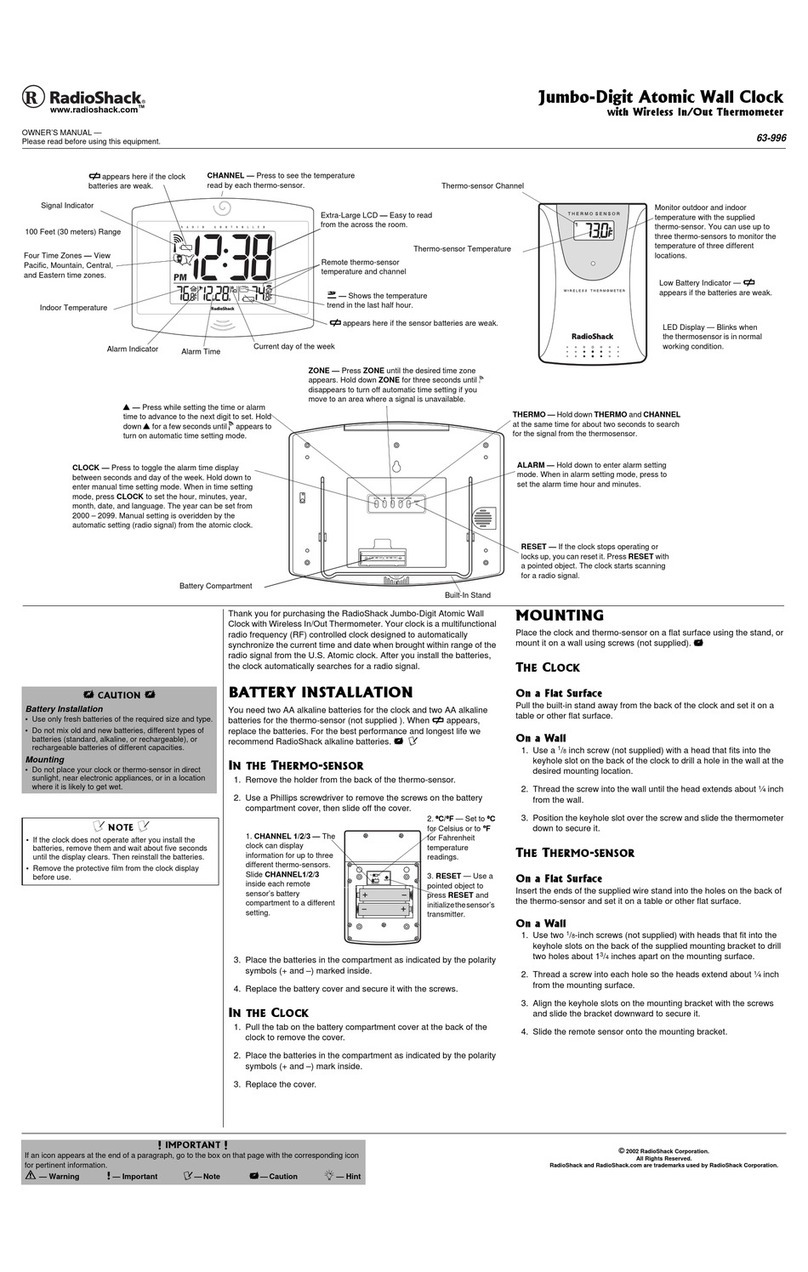
U•
hookup
wire between
the
following points
(IN
Figure 5):
P.
C.
BOARD
R(PIN
111-
EIPIN
51
-
S(PIN
121
-
Q(PIN 10) -
O(PIN51-
U(PIN
7)
-
G(PIN4)
-
T(PINB)-
F(PIN
&>-
N(PIN
8)"
B(PIN
5)-
P(PIN 9)
C(PIN 5)
A(PIN4)
J(PIN
81
K(PIN
91
L(PIN
101
M(PIN 12)
BACK PANEL
S5(80TTOM
TERMINAL)
S5(CENTER TERMINAL)
S5(TOP TERMINAL)
S4(BOTTOM TERMINAL)
S4(TOP TERMINAL)
S7(BOTTOM TERMINAL)
S7(TOP TERMINAL)
S6(BOTTOM TERMINAL)
S6(TOP TERMINAL)
S2(BOTTOM TERMINAL)
S2(TOP
TERMINAU
S3(BOTTOM TERMINAL)
S3(TOP TERMINAL)
Sl(TERMINAL
11
St(TERMINAL
6)
St
(TERMINAL 5)
Sl(TERMINAL
41
St(TERMINAL
3)
NOTE: If
24
Hr
operation
1nd
50Hz
operation
ore
not
used,
points
V,H,
I and Wwill
not
be
used.
9.
Install
tho
Integrated Circuits (IC'sl in
their
respective sockets.
CAUTION:
Tliilii
-•
..
.,._,,
auaceptlble
to
darriilgt
from
l1allc
.,,,._
We~
that
you"--
them
by
the endl.
DO
NOT
TOUCH THE
PINS'
NOTE: A
dot
or
indentation
at
one
end indicates pin 1. Ensure
that
the
IC
's
are positioned
II
shown in Figure 1.
a. Insert
IC
·l (RS1756).
Be
sure
to
align
the
pins with
the
oocket
holes.
They
are
,,,_
of
,oft
metol
and
will bend very easily.
b, Insert
IC-2
and
IC-3 (RS501)
1nd
IC-4 (RS500) using
the
same
precautions
as
in step
a.
10
. Before mounting
the
PC
board
and
Display board, carefully check
all 10ldar connectionL Make sure
that
there
are
no
cold 10ldar joints and
thlt
,older
does
not
bridge across edjacent
copper
lands. Check
that
all
hookup
wiring
is
correct (point~to--poind.
11
.
We
suggest
that
you plug
in
to
a power source
to
make sure all
segments
of
the
LED displays are energized. A
word
of
cautjon
: Be sure
that
the
unit
is
well insulated. Do
not
place
the
unit
on
a metal surface
and avoid touching
any
bare
contact
points.
12. On initial application
of
power
,
the
board
will display all eights,
or
random numbers.
To
start
the
counting
of
the
clock, depress either
S2
or
S3
. Normally, digits 2
and
4
will
not
light until
S2
or
S3
is
depressed and
held.
13.
Rotate
switch S1
to
each
PQs
i
ton
.
If
the
clock
does
not
count.
or
a
segment does
not
light, refer
to
the
troubleshooting chart.
14
. Using
½"
spacers,
U"IOUnt
the
PC
board
on
the
base panel
of
the
case.
15. Again using ½" spacers.
mount
the
Display board
on
the
front panel.
OPERATING INSTRUCTIONS FOR THE CLOCK/CALENDAR
1. When
powet
is
Initially applied,
the
Clock/Calendar will display all
S's. Depressing
either
S2
(Min/Day)
or
S3
(Hr/Mo) will
start
the
count
•
ing
of
the
clock; however,
02
and
04
will
be
blanked.
2.
To
•t
the
clock,
rotate
switch
St
(Counter Select)
to
Set
Clock.
Depress
S3
-
the
seconds digits will revert
to
00
and
the
hours
digit will
advance
at
a 1Hz rate. Depress
S2
and
the
minutes digits will advance
at
a 1Hz rate.
Rotate
S1
to
the
Run Position.
Note
:
Sett
i
ng
the
digits
of
any
counter
will
not
affect
the
other
digits
of
the
counter
or
the
con
•
tents
of
any
other
countar
.
The
time
displayed will hold until
the
switch
is
moved from thi1 Polition. Thia
f•ture
enables you
to
synchronize
your
clock
by
•tting
It
ah-
of
the
reel
time
;
and
,
when real
time
co
in·
cides with Set Time.
rotate
S1
to
Run position.
3.
To
silt
the
calendar,
rotate
St
to
Set
Cal
and
perform
the
same pro-
cedures
II
outlined
in
step
2.
The
digits will
tdvance as
before with
the
following e)(ceptions:
a.
The
colons,
PM
Indicator
and
seconds digits will be blanked.
b.
The
Hr/Mo digits will
advance
only
to
12,
then
revert
to
1.
The
Min/Day digits will
tdvance
to
31.
c.
Rotate
St
to
Run.
The
Min/Day digits will
tdvence
to
28,
30
or
31 days according
to
the
month
.
February
29
must
be
•t
manually.
The
calendar
will
automatically
count
from February
29
to
March 1.
4.
To
•t
the
alarm,
rotate
St
to
Set
Alarm (the seconds digits wi
ll
be
blanked). Advance
the
digits
to
the
desired
sett
i
ng
-u
p
to
24
hours-
and
position
S6
(Alarm On/Off)
to
On.
Then
rotate
St
to
the
Run
posi-
tion.
At
the
preset time
the
alarm
will
sound. It
can
be
turned
off
with
S6
at
any
time;
but
, since
the
A~rm
Time
and
the
reel
time
remain coin-
cident for
60
18Conds,
the
alarm
cannot
be
reset until then. Placing
S6
to
On
again will allow
the
alarm
to
,ound
at
the
•me
pre•t
time
24
hours later.
5. When
the
alarm sounds,
you
can
depre,s
S7 {Snooze switc
h}
for an
extra
10
minutes' sleep. You may get as many "
10
minutes
' e)(tra sleep"
11
you desire
by
depressing S7 until
S6
is
~•ed
to
Off.
6.
To
eet
the
Timer for a radio
or
a small appliance {less
than
600
watts)
rotate
St
to
Set
Radio
(the
seconds digits will
be
blanked). Depress
S3
and
the
hours
digit wi
ll
count
down
from 9
to
0. Depress
S2
and
the
minutes digits will
count
down from
59
to
0.
Set
in
the
length
of'tlme
(hours
and/or
. minutes)
you
want
the
radio
to
play. Place
S4
(Radio
On!OHJ
in
the
On position and
rotate
S1
to
Run.
7. You have a choice
of
three
timer
modes
:
a.
If
you
want
the
radio
to
turn
on
and
play for
the
time
set
in
,
place
S5
(Mode A
&
B)
switch in
the
up
position and
rotate
St
to
Run.
The
radio.
or
applNlnce, will
turn
off
automaticaJly
at
the end
of
the
time
oet
in. Label
this
position-SLEEP
.
b. If
you
wish
to
wake
up
to
music, place
S5
in
the
down position.
The
radio will
come
on
at
the
alarm time
and
play for
the
preset
time
then
turn
off
automatically. You may
tum
the
radio
off
with
S6
at
any time prior
to
the
preset time. Label this position
RADIO
WAKE
UP.
c.
If
you
want
the
radio
to
play for
the
time set in,
turn
off
auto
·
matically,
then
come
t,ack
on
again
at
the
alarrii time, place
S5
in
the
center
position. When
it
comes
on
at
the
alarm ti
me
, it
will play until
turned
off
manually with
S4
. Label this pas:ition
BOTH.
8. Label
the
rest
of
the
controls
according
to
Figure 6.
9. If
you
have
mounted
the
"trim
pot
"
In
the
R4 location, you wi
ll
want
to
adjust
the
50
/60Hz backup circuitry
(battery
backup):
NOTE
:
When
on
battery
power
only
,
the
displays
w ill
be
blanked
Ito
extend
the
life
of
the
batteries)
but
the
clock
will
continue
counting.
a. Operate
the
clock
on
bettery
power
only
(line
cord
unplugged)
for
10
seconds
then
plug
In
the
line
cord
again. Use a
stop
watch
or
sweep
second hand
of
• standard watch
to
compare
the
elapsed
time
of
the
clock
to
that
of
the
watch. If
the
clock
runs
faster
or
slomr,
adjust
R4 -=cordingty. (To increase frequency,
rotate
R4
clockwise).
b. Gradually increase
the
operating time
on
battery
power
up
to
30
seconds, edjusting R4 each time. You should
be
able
to
get
an accuracy
of
within
one
second per
minute
.
c. If
you
have a frequency COunter
you
can adjust R4 so
that
D1
ii
at
1.05KHz for
60Hz
operation
and
at
875Hz
for 50Hz.
oper
-
ation
. (This should also
be
done
on
battery
power
on
l
y)
.

