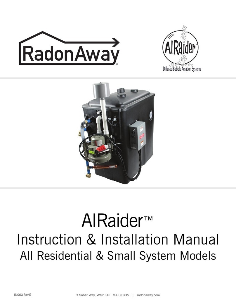
RadonAway AIRaider 433-S50 Parts list manual

AIRaider™
Instruction & Installation Manual
All Residential & Small System Models
IN063 Rev.D 0120 3 Saber Way, Ward Hill, MA 01835 | radonaway.com

Page 2 of 22
IN063 Rev.D 0120 3 Saber Way, Ward Hill, MA 01835 | radonaway.com
1. PRE-INSTALLATION............................................................................................................ 3
1.1SafetyMaers........................................................................................................................................................................4
1.2.WaterFlowRequirements...................................................................................................................................................5
1.3.UnpackingandLocatingSystemComponents..................................................................................................................5
1.3.1.UnpackAllSystemComponents..................................................................................................................... 5
1.3.2.LocateAllComponents......................................................................................................................................5
1.4.UseQualiedTechnicians...................................................................................................................................................5
1.5.FullWaterTest......................................................................................................................................................................5
2. INSTALLATION INSTRUCTIONS.....................................................................................6
2.1.SystemLocation....................................................................................................................................................................7
2.2.ReadyingtheAIRaiderTMforInstallation..........................................................................................................................7
2.3.PlumbingHook-up...............................................................................................................................................................9
2.4.ElectricalHook-up.............................................................................................................................................................11
2.5.VentLineInstallation.........................................................................................................................................................14
2.6.RemoteAirIntake..............................................................................................................................................................15
2.7.SystemStart-up.................................................................................................................................................................16
2.8.SystemCheck......................................................................................................................................................................17
2.9.RecommendedInstallationOptions:OverowProtectionandAlarm ....................................................................17
3.RETESTING..............................................................................................................................18
4. MAINTENANCE...................................................................................................................18
4.1.SixMonthService(recommended)..................................................................................................................................18
4.2.AnnualService(required)..................................................................................................................................................19
4.3RecommendedAddiionalService....................................................................................................................................19
5. TROUBLE SHOOTING........................................................................................................20
LIMITEDWARRANTY.............................................................................................................21
APPENDICES
A.1.PumpSpecication,433-S50Systems,pumpmodel20DOMO5121+1...............................................................insert
Figure 1 a,b,c-TypicalSystems(433-S,433,321)..................................................................................................................................6
Figure 2 -Pump&BypassAssembly(433/321)....................................................................................................................................7
Figure 3-InstalledSystem(433,321)......................................................................................................................................................8
Figure 4-PlumbingInstallation(433-S50).............................................................................................................................................9
Figure 5-PlumbingInstallation(433-S50X)........................................................................................................................................10
Figure 6-WiringDiagram433115V/230V............................................................................................................................................12
Figure 7-WiringDiagram433S50/115V..............................................................................................................................................13
Figure 8-WiringDiagramS50X/115V..................................................................................................................................................14
Figure 9-WiringDiagram321/115V.....................................................................................................................................................15
Figure 10-VentLineConnection..........................................................................................................................................................16
Figure 11-VentLineInstallation(2inch)............................................................................................................................................16
Figure 12-VentLineInstallation(3inch)............................................................................................................................................16
Figure 13-AirFilter................................................................................................................................................................................17
Figure 14-AirIntakeConnection.........................................................................................................................................................17
Figure 15-InstalledAIRaiderTM(433-S50)...........................................................................................................................................18
Table of Figures
TABLE OF CONTENTS & FIGURES

Page 3 of 22
IN063 Rev.D 0120 3 Saber Way, Ward Hill, MA 01835 | radonaway.com
1. Pre-Installation
WARNING: FAILURE TO INSTALL AND MAINTAIN THE UNIT ACCORDING
TO THESE INSTRUCTIONS MAY RESULT IN PERSONAL INJURY OR PROPERTY
DAMAGE.
TheAIRaiderTMSystemsarediusedbubbleaerationsystemsfortheremovalofradonandother
VOC’sfromresidentialandmunicipalwatersupplies.Thisinstallation/operationmanualisdesigned
toguideprofessionalsthroughthesafeandproperinstallationoftheAIRaiderTMSystems.
BeforebeginningtheinstallationoftheAIRaiderTMSystem,thereare5itemstobeconsidered.
Theyare:
1. Safety
2.InstallationSiteRequirements
3.InspectionofSystemComponents
4.NecessityforQualiedTechnicians
5.KnowledgeofallContaminantsintheWater
1.1. Safety Maers
Safetyisthemostimportantstepintheinstallationprocess.Neverperformanystepoftheinstallation
thatyouarenotqualiedtoperform(i.e.Electricalorplumbinghookup).Itisimportantthatyouread
throughtheentiremanualpriortobeginningtheinstallation.Whenperformingtheinstallation,work
slowlyanddeliberately.Followallinstructionscarefullyandnevertakeshortcuts.Ourteamof
techniciansisavailabletoansweryourquestionsat800-355-0901.
WORK SAFELY!
PRE-INSTALLATION
1

Page 4 of 22
IN063 Rev.D 0120 3 Saber Way, Ward Hill, MA 01835 | radonaway.com
1.2. Water Flow Requirements
ThestandardresidentialAIRaiderTMSystemsaredesignedforusewithwaterowsupto20gallons
perminute(GPM).*Thesystemcomesequippedwithanoutowballvalve.Ifhigher/lowersystem
outowisneeded,open/closetheballvalvebytheamountnecessarytobalancethesystem.Thewell
pumpoutputmustproduceatleast1GPMmorethantheoutputoftheAIRaiderTM(i.e.welloutput=
8GPM;AIRaiderTMoutowseing=7GPM)forpropersystemperformance.Ifthewellpump
outputislessthanthesystemoutputtheAIRaiderTMwillrundryandpossibledamagemayoccur.To
preventthisfromoccuringthewaterowratemustbedeterminedbeforethesystemisinstalled.
*Some AIRaiderTM Systems are not recommended for high ow residential properties. All repressurization systems
(except for the AIRaiderTM EZ95,433-S50 & 433-S50X) are sold separately. Proper repressurization system
sizing is required to meet water ow needs. Consult manufacturer if assistance is needed for system selection.
Inordertodetermineavailablewaterowratethefollowingisneeded:
•GardenHose
•Five-GallonBucket
•AStopWatchorWatchwithaSecondHand
Or
•AWaterFlowMeter
Household water use must be discontinued during the following ow rate test.
Mid-Range Flow Rate Test:
1.AachgardenhosetothedrainconnectiononthebaseoftheWellPressureTank.
2.Openthedrainvalveandrunwaterfor15minutes.
3.After15minutes,checkthepressuregaugeonthewellsystem.Adjustthedrainvalve(openor
close)asneededtomaintaintherequiredrunningsystempressure(constantpressureongauge)
withthewellpumprunningcontinuously.
4.Runfor5minuteswhileensuringthatthepressureisnotuctuating.
5.Runwaterfromthehoseintoavegallonbucket.Usingastopwatch,timehowmanysecondsit
takestollthebucket(Zsec.).
6.DeterminetheGPMbydividing60secondsbythenumberofsecondsittooktollthebucket
(Zsec.).Multiplytheanswerby5gallons.ThisgivesyoutheGPM. GPM = ( 60 / Z ) x 5
7.Repeatsteps5and6andaveragethe2numbers.Theansweristhewellpumpoutputingallons
perminute.Itisrecommendedthatthisnumberbeindeliblyrecordedinanobviouslocation,
togetherwiththedateoftest,asitwillberequiredwhenseingtheAIRaiderTMSystemandmay
berequiredforfuturetroubleshootingofthewellpumpsystemortheAIRaiderTMSystem.
PRE-INSTALLATION
1

Page 5 of 22
IN063 Rev.D 0120 3 Saber Way, Ward Hill, MA 01835 | radonaway.com
1.3. Unpacking and Locating System Components
1.3.1. UnpackAllSystemComponents
Removeallpackingmaterialanddiscardappropriatelyawayfromtheworkarea.
1.3.2. LocateAllComponents
Checktoensureallcomponentsareintactandincludedinshipment.(SeeFigure5and8)
Includedcomponentlist(mayvarywithorder):
•TankAssemblywithSolenoidAssembly
•ControlPanel*andFloatSwitches
•SubmersiblePump**
•JetPumpandBladderTankAssembly***
•Brass–BypassAssembly,PumpBrass,andTankBrass****
•InstallationKit–Manual,PressureGauge,etc.
*Model321doesnotcomeequippedwithacontrolpanel
**Mountedinternallyon433-S50and433-S75Systems,notsuppliedwith433and321Systems.
***Pumppackagesaresoldseparatelyon321and433Systems,andwillvarywiththeorder.
BladderTanksaresoldseparately.
****Soldseparatelyon321and433Systems.Standardsystemsareequippedfora¾”
plumbingconnection.1”plumbingconnectionisavailableon433Systemsonly(Not433
433-S50or433-S75).Pleasespecifyplumbingconnectionrequirementswhenordering.
BypassAssemblyisintegralon433-S50SystemsOnly.
1.4. Use Qualied Technicians
ALicensedPlumber,Electrician,Contractorand/orCertiedWaterTreatmentSpecialistmaybe
requiredtoinstalltheAIRaiderTMSysteminaccordancewiththeinstallationinstructions.Allwiring
mustbeperformedinaccordancewiththeNationalFireProtectionAssociation’s(NFPA)”National
ElectricalCode,Standard#70”-currenteditionforallcommercialandindustrialwork.Allwiring
mustbeperformedbyaqualiedandlicensedelectrician.CheckyourLocalandStateCodeand
Licensingrequirements.Failuretofollowtheinstructionsmayleadtopoorsystemperformanceand/
orpossiblesystemdamage.
The Installation must comply with all applicable Local and State Codes and
NFPA National Electrical Code, Standard #70!
1.5. Full Water Test
AfullWaterSampleAnalysismustbeperformedtodeterminethequalityofthewaterthatrequires
treatment.Inmanywatersupplies,contaminantsotherthanradonarepresentandmayneedtobe
pre-treatedinorderfortheAIRaiderTMtoworkproperly.TheAIRaiderTMSystemisonlyeectivefor
theremovalofradonandsomeotherVOC’s.TheAerationProcessemployedbytheAIRaiderTM
Systemandotherradonremovalsystemscanworsenproblemsduetoironormanganesecontaminantsin
thewatersupply.For optimal removal of radon or other VOC’s, other contaminants such as iron or
manganese must be removed before the water supply enters the AIRaiderTM System. Installation of
a sediment lter is highly recommended as a pre-treatment of the water supply. The lter should
be routinely cleaned or replaced.
FAILURE TO REMOVE OTHER CONTAMINANTS INCLUDING SEDIMENT CAN REDUCE
SYSTEM EFFECTIVENESS AND MAY RESULT IN SYSTEM DAMAGE , COMPONENT MALFUNCTION,
PROPERTY DAMAGE, AND PERSONAL INJURY.
PRE-INSTALLATION
1

Page 6 of 22
IN063 Rev.D 0120 3 Saber Way, Ward Hill, MA 01835 | radonaway.com
2. Installation Instructions
OVERVIEW
Nowyouarereadytobegintheinstallationprocess.TheeightstepstoproperlyinstalltheAIRaiderTM
Systemarelistedbelow.Readallcomponentsofeachsteppriortobeginningtheactualinstallation.
1.SystemLocation
2.ReadyingtheSystemforInstallation
3.PlumbingHook-up
4.ElectricalHook-up
5.VentLineInstallation
6.RemoteAirIntakeInstallation
7.SystemStart-up
8.SystemCheck
9. Install Overow Protection and Alarm Prior to Use.
It is recommended that a Flood Stop (P/N 28276, sold separately) be installed prior to use of
this system to provide point of leak detection, whereby a motorized ball valve will
automatically shut o the system and prevent potential overows should debris clog
a shut-o valve. A basement water alarm also should be installed to warn residents of
water tank overows.
SAFETY TIP: Do Not undertake any step for which
you are Not Qualied.
Figure 1 a,b,c
TypicalSystem
(RepressurizationSystemsnotshown,soldseparatelyon321,433and433-1)
433-S50 321433 & 433-1
INSTALLATION INSTRUCTIONS
1 2

Page 7 of 22
IN063 Rev.D 0120 3 Saber Way, Ward Hill, MA 01835 | radonaway.com
2.1. System Location
WhenselectingthelocationfortheAIRaiderTMSystem,vefactorsshouldbeamongthoseconsidered:
1. SystemPlumbingHook-up.Findalocationthatwillminimizetheamountofplumbing
necessary,thisistypicallyinproximitytothewelltank.
2. ElectricalHook-up.Keepinmindtheneedforaccessibilitytoa20Ampdedicated120VAC
powersupplyor30Ampdedicated230VACfor230V433Systems.
3. ExhaustLineVenting.Thelocationofthesystemmustallowforoutsideventingofthe
systemexhaustabovetheeaveofthestructure.Themanufacturerrequiresthattheexhaust
pipepitchbacktowardthesystem(seeSection2.6).
4.RemoteAirIntake.Ifthesystemmustbeinstalledinanareawithquestionableairquality
(i.e.furnaceroom,garage,crawlspace)thenductingfromtheairintaketoaremotelocation
havinggoodairqualitymayberequired.
5.SystemMustBeLevel.Thesystemshouldnotbelocatedonasignicantslopeasthismay
impedesystemperformance.
Placethesysteminthelocationacceptabletocustomerthatmaximizestheeaseofinstallation.
AllLocalandStatecodesaswellasanyapplicableAARST,EPAand/orStateRadonstandardsmust
beadheredtowhenlocatingtheAIRaiderTM(i.e.awayfromelectricalpanel,furnace,exits,etc.).
2.2. Readying the AIRaiderTM for Installation
For 433 and 321 systems (433 Illustrated). This section does not apply to Systems with integral pumps (433-S50 & 433-S50X Systems).
1.IfusingtheGrundfosMQ3-45PumpaachMount-
ingBrackettowallasshowninFig.3(page8).Note
bracketholeheightisspecictotheGrundfosMQ3-
45.Ifusingadierentpumpadjustbracketheightas
requiredtoplacepumpsuctionpipecenterlineatthe
systemoutletcenterlineasspeciedinFig.3.
Note: Short horizontal pipe run from system outlet to pump inlet is optimal. If this
pump location is impractical because of space constraints the pump may be located
remotely at a higher location, but pump lift, pipe diameter, and equivalent pipe length
must comply with limits specied in the pump installation instructions.
Do not mount pump lower than shown as removal of the pump for
service may result in tank contents siphoning out onto the oor!
2.InstalltheSuctionCheckValveprovidedwiththe
GrundfosMQ3Pumpintothepumpinletasshownin
thepumpinstallationinstructions.Thiswillprevent
lossofpumpprimeandpossibleinterruptionsinthe
watersupplytothehouse.Removetheprimingplug
fromthepumpandaddthespeciedvolume(See
PumpInstallationInstructions)ofwatertothepump.
Eitherre-installtheprimingplugorinstalla⅜”NPT
x2”longpipenippleandaacha¼”NPTPressureGauge
withwith¼”x⅜”FNPTReducertothepipenipple(Fig.2).
Figure 2
Pump&BypassAssembly
INSTALLATION INSTRUCTIONS
1 2

Page 8 of 22
IN063 Rev.D 0120 3 Saber Way, Ward Hill, MA 01835 | radonaway.com
3.Sitthepumpontothemountingbracketandconnectpumpinlettosystemoutlet.Thesystemoutlet
isprovidedwitha¾”SharkbiteConnectionsuitablefor¾”NominalCopperTubeorPexTube;
insertionlengthintoSharkbiteFiingis1”.Additionalingswillberequiredtoconnectthetubeto
the1”MNPTthreadedconnectionontheMQ3-45Pump.Fiingsrequiredmayvarywithpumpused.
Cutthetubingtothelengthrequiredtoalignthepumpbasewiththemountingholesinthepump
mountingbracket.Boltthepumptothemountingbracket.
4.WiththeSystemlocatedasdesired,installthepipe/tubefromthepumpdischargetothedesired
locationofsupplytohouse.Atthehouseendateeisrequiredtoaccommodatesupplytohouseandto
SystemBypassConnection.Fiingswillberequiredtoconnecttothe1”MNPTthreadedconnectionon
theMQ3-45Pump.Fiingsrequiredmayvarywithpumpused.TheoptionalBladderTankhasa¾”
MNPTthreadedconnection.Ateewillberequiredifthebladdertankisinstalled,otherwiseanelbow
maybeusedatthesamelocation.Tofacilitateremovalofpumpforservice,aquickdisconnect
(sharkbiteasillustrated,orpipeunion)isrecommendedonthepumpsideoftherequiredSystem
OutletValve(normallyopenballvalve).
5.Installpipe/tubefromSysteminlet(Fig.2)tothedesiredlocationofthesupplyfromthewelltank.
Atthesupplyendateeisrequiredtoaccommodatesupplyfromthewellandthesystembypass
connection.Thesysteminletisprovidedwitha¾”SharkbiteElbowsuitablefor¾”NominalCopper
TubeorPexTube,insertionlengthintoSharkbiteFiingis1”.ASystemInletValve(normallyopen
ballvalve)isrequiredbetweentheteeandSharkbiteElbow.
6.Installthepipe/tubebetweentheteesatthedesiredlocationsofthesupplytohouseandthesupply
fromwell.ASystemBypassValve(NormallyClosedBallValve)isrequiredbetweenthetees.
Figure 3
Installed433NDSystem
INSTALLATION INSTRUCTIONS
1 2

Page 9 of 22
IN063 Rev.D 0120 3 Saber Way, Ward Hill, MA 01835 | radonaway.com
2.3. Plumbing Hook-up
All Plumbing should be performed in accordance with Local and State Codes by a
Qualied Plumber.
1.Shutothewatermainvalve
locatedafterthepressuretank.
2.Drainthewaterline.
3.Plumbthesystemintothewaterline
afterthepressuretankandallother
watertreatmentequipment.
4.Plumbthewaterlinefromthe
existingpressuretankintotheInletTee.
5.Plumbthewaterlinetothehouse
intotheOutletTee(Fig.2,4or5
dependingonSystemandPump).
Aowrestrictororgatevalveinthe
waterlinetothehouseisrequiredfor
balancingthesystemow.ABladder
Tank,minimumcapacity5gallonsis
requiredfor433-S50Systems(20gal.
min.for433-S50X).
WARNING: Bladder Tank must be
supported by hanger aached to wall
or joist.
6.MakingsuretheBypassvalveisopen
andInletandOutletValvesareclosed,
slowlyopenthewatermainvalveand
checkforleaks.
7.Slowlychangebypasstothe“service”conguration,Bypassvalveclosed,inletandoutletvalves
open.PrimejetpumpasperManufacturersInstructions(SeeenclosedJetPumpManual)ifnot
previouslyprimed.Notethatintegralpumpon433-S75and433-S50systemswillselfprimewhen
thesystemtankislled.
Figure 4
PlumbingInstallation433SNDSystem
INSTALLATION INSTRUCTIONS
1 2

Page 10 of 22
IN063 Rev.D 0120 3 Saber Way, Ward Hill, MA 01835 | radonaway.com
INSTALLATION INSTRUCTIONS
1 2
Figure 5
PlumbingInstallation433-S50X

Page 11 of 22
IN063 Rev.D 0120 3 Saber Way, Ward Hill, MA 01835 | radonaway.com
2.4. Electrical Hook-up
All Electrical Work should be performed in accordance with Local and State Codes, and
NFPA National Electrical Code, Standard #70 by a Qualied and Licensed Electrician .
WARNING: Never perform electrical work while standing in water.
Do not aempt wiring on a live circuit.
WARNING: Power Supply Voltage must match the voltage marked on the
System Nameplate. Improper wiring may result in system damage.
1.Turnmainpowerswitch,locatedontheAIRaiderTM,tothe“O”position.
2.ConnecttheJetPumppowercordtotheJetPump.(DoesnotApplyto433-S50or433-S50X
Systems,pumpisfactoryconnected)NotetheJetPumppowercordfromtheAIRaiderTMisprovided
withanelectricalreceptacle.TheJetPumpmaybeconnectedeitherbyconnectingasuitablepower
leadwithplugandpluggingintothereceptacleorbyremovingthereceptaclefromtheJetPump
powercordandconnectingthepowercorddirectlytothepump.Followwiringinstructionslocated
intheenclosedJetPumpManual.
Warning: Never remove the Receptacle from the Jet Pump Power Cord without connecting the wires
thus exposed to the jet pump, inside the Jet Pump Electrical Enclosure. Always secure the Jet Pump
Enclosure Cover after making electrical connections.
3.On433-S50XunitsonlytheinstallermayneedtodisconnecttheArmoredCablesuppliedinorder
toinstallthePressureSwitch.TheArmoredCablemayrequiretrimmingtothedesiredlengthbefore
reconnecting.ConnectperthewiringdiagramFigure8Page14.
4.Makesureallconnectionsinthecontrolpanelaretight.
5.Bringinpowertothecontrolpanelusingtheholeprovided,eitheranappropriatestrainrelief
bushing,orelectricalconduiting(s),withcorrectlyratedelectricalwireorcablemustbeusedin
accordancewithallapplicableElectricalCodes.
6.Connectthepowerlinetothecontrolpanelasshownintheapplicablewiringdiagram(SeeFigures
6,7,8,9-onpages12-15).
7.Connectpowerlinetopowersource*.TherequiredVoltageiseither120Vor240Vandisindicated
byan“X”markedinthecheckboxnexttoeitherthe120Vor240Vmarkingonthenameplate.Follow
allcoderequirementsregardingwireandcircuitbreakersize.
* Manufacturer recommends that the AIRaiderTM System be directly wired to the panel on a
dedicated circuit.
INSTALLATION INSTRUCTIONS
1 2

Page 12 of 22
IN063 Rev.D 0120 3 Saber Way, Ward Hill, MA 01835 | radonaway.com
Figure 6
AIRaider321NDand433NDWiringDiagram115V
321ND and 433ND 115V - 1Ph-60Hz Power Supply
INSTALLATION INSTRUCTIONS
1 2

Page 13 of 22
IN063 Rev.D 0120 3 Saber Way, Ward Hill, MA 01835 | radonaway.com
Figure 7
AIRaider433-S50(X)NDand321-S50XWiringDiagram115V
433-S50(X)ND and 321-S50X with ½HP Submersible Pump 115V-1PH-60Hz Power Supply
INSTALLATION INSTRUCTIONS
1 2

Page 14 of 22
IN063 Rev.D 0120 3 Saber Way, Ward Hill, MA 01835 | radonaway.com
2.5 Vent Line Installation
Useonly2”,3”or4”Schedule40PVCorequivalentpipeforventline.
FollowallapplicableAARST,EPA,and/orStateStandardsforRadon
orVOCventing.
1.PlacethelidoftheAIRaiderTMontothetankandclampintoplace
usingtheHexHeadScrewsandWashersprovided.
2.ConnectventlinetoAIRaiderTMlidusingtheenclosedrubber
coupling(SeeFig.10).
3.Theventlinemustberoutedinamannerthatallowsthesystem
toexhaustabovetheleveloftheroof(seeFig.11).
Note: When “Freeze Up” is posssible a minimum pipe diameter of 3” is
recommended (See Fig. 12).
4.Theventlinemustbepitchedbacktowardthesystemtoprevent
condensationbuildup.
5.Cementallingsinamannerthatensuresnoleakagewilloccur.
Becertaintousecementthatissuitableforpotablewaterapplications.
6.Installweathercapontopoftheventline.Thiscapshouldnot
restrictairowandmustpreventrain,snowandothercontaminants
fromenteringtheventline.
Failure to install a proper vent line
may cause contamination of the
water, outgassing of contaminants
into the building, and/or limit
system performance.
* The Manufacturer has found that vent lines less than 250 equivalent
linear feet do not cause a decrease in contaminant removal percentages.
90° Bend = 15 Equiv. Linear Ft ; 45° Bend = 7 Equiv. Linear Ft.
Figure 9
VentLineInstallation(2inch)
Figure 120n(3inch)
Figure 8 VentLineConnection
INSTALLATION INSTRUCTIONS
1 2

Page 15 of 22
IN063 Rev.D 0120 3 Saber Way, Ward Hill, MA 01835 | radonaway.com
2.6 Install Air Filter (Fig. 11)
1.InstallairlterprovidedusingthePVCpipeandingsprovided
(Fig14).
2.6.1 Remote Air Intake (Fig. 12)
If a Remote Air Intake is required because of Air Quality or Quantity
issues then Use Only 1-¼” or larger Schedule 40 PVC or equivalent pipe
for the air intake line.
1.Connectairintakelinetotheblowerusingtheproperreducer
coupling.
2.Runtheintakelinefromthepipeconnectionontheblowerto
thelocationselectedforairintake.
Note: A rubber coupling or similar means to disconnect the intake line from
the is recommended.
3.ConnecttheAirFiltertotheventlineusingtheproper
reducercoupling.
If the air intake is located outside, the lter or intake must be
mounted high enough o the ground to prevent the drawing in
of snow, water and other contaminants. Do not locate the air
intake in the vicinity of vents from furnaces, barbecue grills, etc.
Note: In-Line Air Filters are also available from the Manufacturer. Figure 12
AirIntakeConnection
Figure 11
AirFilter
INSTALLATION INSTRUCTIONS
1 2

Page 16 of 22
IN063 Rev.D 0120 3 Saber Way, Ward Hill, MA 01835 | radonaway.com
2.7. System Start-Up
1.Removecoverandlidandpour¼
cupofchlorineintotherstchamber.
(Thiswilldisinfectthesystem.)
Replacethelidmakingsureall
screwsaresecure.
2.Checkthatallplumbingand
electricalconnectionshavebeen
properlycompleted.
3.Slowlychangebypasstothe
“service”conguration.Check
forleaks.
4.TurnpowerswitchforAIRaiderTM
to“On”.SolenoidValveswillnow
openallowingwaterintothesystem.
Theaerationprocesswillalsostart.
Checkforleaks.
5.AllowtheAIRaiderTMtoll
withwater.
6. On 433-S50 & 433-S50X SystemsthesubmersiblepumpinstalledintheAerationTankwillself
primewhentherisingwaterlevelliftsthepumpoatandthepumpstarts.Followpumpmanufac-
turer'sinstructionstoprimeotherexternalpumps.Thenormaloperatingrangeisnominally40PSI–
60PSI*butwillvary(PressureSwitcheson433-S50&433-S50Xfactorysetat38PSI-55PSIapprox.).
Do Not Aempt to Adjust the Pressure on 433-S50 or 433-S50X Systems, as this may result
in the pump not shuing down as it aempts to reach too high a set pressure. This problem
may not occur immediately but can occur later when a low voltage supply occurs due to high
electrical demand or other external factors. The factory pressure seing is deliberately less
than maximum to provide an allowance for a low voltage supply event. Continuous
operation of the pump when there is no water demand will overheat the system causing
the thermal overload to trip and consequent pump shut down.
Note: Priming process for the jet pump and pressure seings may vary with repressurization system.
Figure 13
InstalledAIRaiderTM433-S50
INSTALLATION INSTRUCTIONS
1 2

Page 17 of 22
IN063 Rev.D 0120 3 Saber Way, Ward Hill, MA 01835 | radonaway.com
2.8 System Check
1.Runthesystemthroughacoupleofcyclestoensureallcomponentsareworkingproperly.
2.Theblowertimerispresetfor5minutesdelay.Afterthesolenoidvalvesshut,checkthattheblower
continuesrunningforthepresetnumberofminutesdelay.
3.Openthetankandcheckthesystem.
a.Removethetanklid.
b.Lowerthewaterlevelinthetankbyopeningabathtubtap,orsimilar,withintheresidence.
Theoatswillfallwiththewaterlevel.Theminimumwaterlevelisreachedwhenthelower
oatdrops(excepton433-S50&433-S50Xsystemswhereminimumwaterleveloccurswhen
themiddleoatdrops).Therewillbeanaudibleclickandthesolenoidswillopenallowing
thetanktostartlling;theblowershouldalsostartrunning.Thewaterlevelmustriseregard
lessofhowmanytapsareopenwithintheresidence.
c.Whilethetankisllinglifttheloweroat(middleoaton433-S50&433-S50X),waterin
owshouldstopandtheblowerwillremainrunning(untiltheendofthepresetdelay).
Releasetheloweroat.
d.Whilethetankisstillllinglifttheupperoat;waterinowshouldstopandtheblower
willremainrunning.Releasetheupperoat.Pushingdowntheloweroaton433-S50
and433-S50XSystemswillshutothepump.
e.Remembertoshutoanyopentapswithintheresidence.
4.Replacethelidandsecurewiththefastenersprovided.WiththeSystemrunningcheckthelidfor
airleaksbetweenlidgasketandtank.Ifleaksoccurthefastenersshouldbetighteneduntilleaksare
eliminated.
5.Makesureyouhaveproperlylabeledthesystemwiththenecessaryinstallerinformation(i.e.company
name,phone#,dateinstalled,etc.)andyouhaveleftallsysteminformationwiththehomeowner.
6.TheAIRaiderTMSystemisnowoperational.
2.9 Recommended Installation Options: Overow Protection and Alarm
1.ItisrecommendedthataFloodStop(P/N28276)beinstalledpriortouseofthissystemto
providepointofleakdetection,wherebyamotorizedballvalvewillautomaticallyshuto
thesystemandpreventpotentialoverowsshoulddebrisclogashut-ovalve.
2.ItisrecommendedthatabasementWaterAlarmbeinstalledtowarnresidentsofwatertank
overowsorsystemleaks.
INSTALLATION INSTRUCTIONS
1 2

Page 18 of 22
IN063 Rev.D 0120 3 Saber Way, Ward Hill, MA 01835 | radonaway.com
3. Retesting
AftertheAIRaiderTMinstallation,theinstallershouldperformanotherwateranalysistoensure
propersystemperformance.Thissampleshouldbeperformedoneweekafterthedateofinstallation.
Sampling Procedure:
1.Removeaeratorfromfaucetorspigot,ifapplicable.
2.RunwatersothattheAIRaiderTMoperatesfortwocycles.
3.Turnowaterfor5minutes.
4.Turnwateronandproceedwithsamplingasperthelaboratoryinstructions.
4. Maintenance
PropermaintenanceoftheAIRaiderTMcanpreventpossiblesystemfailureandprovideyearsof
trouble-freeservice.
4.1. Six Month Service (recommended)
ThefollowingproceduresshouldbefollowedtomaintaintheAIRaiderTM:
•Checkand/orcleantheblowerairintakelter.
• Check and/or clean any lters or strainer installed on the inlet line to the AIRaiderTM. In
installations with particularly high levels of sediment, cleaning of lters may be required
more frequently.
•Checkandcleaninletscreenonpump.
•Usingawet/dryvac,cleansedimentfromboomofaerationtankifnecessary.
•Clean(ifnecessary)tankanddiusersofallmineralbuildup.
•Chlorinatetankandlinesbypouring¼cupofchlorineintotherstaerationchamber.
•Checkallcontrolpanelconnectionsandelectricalcomponents(blower,pump,timer,fuses,etc.)for
properoperation.
• Check oat switches for proper operation.
•Inspectventlineforpossibleobstructions.
•Runsystemthroughtwocyclestoensuregoodworkingorder.
RETESTING AND MAINTENANCE
1234

Page 19 of 22
IN063 Rev.D 0120 3 Saber Way, Ward Hill, MA 01835 | radonaway.com
4.2 Annual Service (required)
ThefollowingproceduresshouldbefollowedannuallytomaintaintheAIRaiderTM:
•Cleansolenoidsandswitchcoillocations.
•Checkallhoseconnections.
•Checkand/orcleantheblowerairintakelter.
• Check and/or clean any lters or strainer installed on the inlet line to the AIRaiderTM.
•Checkandcleaninletscreenonpump.
•Usingawet/dryvac,cleansedimentfromboomofaerationtankifnecessary.
•Clean(ifnecessary)tankanddiusersofallmineralbuildup.
•Chlorinatetankandlinesbypouring¼cupofchlorineintotherstaerationchamber.
•Checkallcontrolpanelconnectionsandelectricalcomponents(blower,pump,timer,fuses,etc.)for
properoperation.
• Check oat switches for proper operation.
•Inspectventlineforpossibleobstructions.
•Runsystemthroughtwocyclestoensuregoodworkingorder.
•PerformWaterTest.
4.3 Recommended Additional Service*
• Every3years,replaceallhoses.
• Every3-5years,replacethesolenoidvalves.
*DuringAnnualService
MAINTENANCE
1234

Page 20 of 22
IN063 Rev.D 0120 3 Saber Way, Ward Hill, MA 01835 | radonaway.com
Symptom Solution
Nowaterinhouse
Waternotenteringsystem
JetPumpnotfunctioning
Pressureintankislessthan40PSI
Lowwaterowatfaucets
Blowernotrunning
Blowerdoesnotstoprunning
Loudbangingwhensolenoidsshut
Pumpisshortcycling
Pumpwon'tshuto
Solenoidschaerwhenclosing
Systemrunningdry
•Checkpower:Switchinonposition,circuitbreakeratpanelinon
position,fusesincontrolpanelintact.
•Checkpressureintank.Ifbelowtheproperseings,resetthepump
asdescribedinSystemStart-up(p.17).
•BypassSystem.Ifthereisstillnowater,mainwellpumpmaynot
befunctioning.
•Checkon/ooatforproperoperation.Replaceifnecessary.
•Checksolenoidsforproperoperation.Replaceifnecessary.
•Checkoatswitchesforproperoperation.Replaceifnecessary.
•Checksedimentstrainerand/orlter(ifapplicable)andcleanifnecessary.
•Checkfuseincontrolpanel.
•Checkbreakeratelectricalpanel.
•Replacejetpumpifnecessary.
•ResetjetpumpasdescribedinSystemStart-up(p.17).
•Checkbladdertank.
•Replacejetpumpand/orbladdertankasnecessary.
•Clearsedimentstrainersonfaucets.
•Clearpumpinletscreen/waterinjector.
•Replacepumpifnecessary.
•Checkfusesincontrolpanel.
•Replacetimerifnecessary.
•Replaceblowerifnecessary.
•CheckOn/Ooatforproperoperation.
•CheckTimerSeings.
•ReplaceTimerRelayifnecessary.
•Installwaterhammersuppressororloopofexiblehoseinpumpinletline.
•Shortenthelengthofpipebetweenthewellpressuretankandthesystem.
•Bladdertankmayberuptured.Replaceifnecessary.
•Checkpressureswitchonpumpforproperoperation.
•Callforsupport.
•CheckOn/Ooatforproperoperation.Replaceifnecessary.
•Checksedimentstrainerand/orlter(ifapplicable)andcleanifnecessary.
•InstallaowrestrictorormeterdowntheballvalveuntiltheAIRaiderTM
outowis1GPMormorelessthanthewaterowenteringthesystem.
TROUBLE SHOOTING
12345
This manual suits for next models
3
Table of contents
Other RadonAway Water System manuals
Popular Water System manuals by other brands

clage
clage Zip HydroTap G4 BCS 100/75 Operating and installation instructions

Kallipr
Kallipr Captis Pulse Lite 1.0 manual

Zip
Zip HydroTap G4 installation instructions

Armatec
Armatec reflex Variomat Basic Original operating manual

JABSCO
JABSCO 31765-0092 manual

Conel
Conel Flow Box Installation and operation instruction