Raider 40 User manual

Raider 40 Manual Military version
0
Raider No R40ES-001-15-2
January 2015
Raider 40 Parts/Assembly Manual
Part No. RPAM 40ES-001
C-130
Air Dropped
Submarine
Launched
Raider Part No. R40ES-001
RAIDER
Supplement to Raider Service Manual
No. R40 ES-001-15-3


Raider 40 Manual Military version
Raider Parts and Assembly Manual R40ES-001-15-2 describes part numbers and
illustrates how the Raider subassembly is put together. This manual is a
supplement to the Raider Service Manual R40ES-001-15-3 that describes in
detail all steps required to repair the Raider 40.
Raider Outboard makes no warranty, express or implied, regarding the use of
this data. Raider
Inc. assumes no responsibility for errors or omissions nor
assumes any liability for damages
resulting from the use of the information
contained herein. In some cases a part design may have
changed since this
manual was published or may not apply to your particular engine serial number, or
a service/parts bulletin may have been issued containing important information
pertaining to this
model and/or a particular part. Some parts may be serial
number and/or model number specific.
You are strongly advised to contact Raider
for all up to date information (321) 403-3585
.
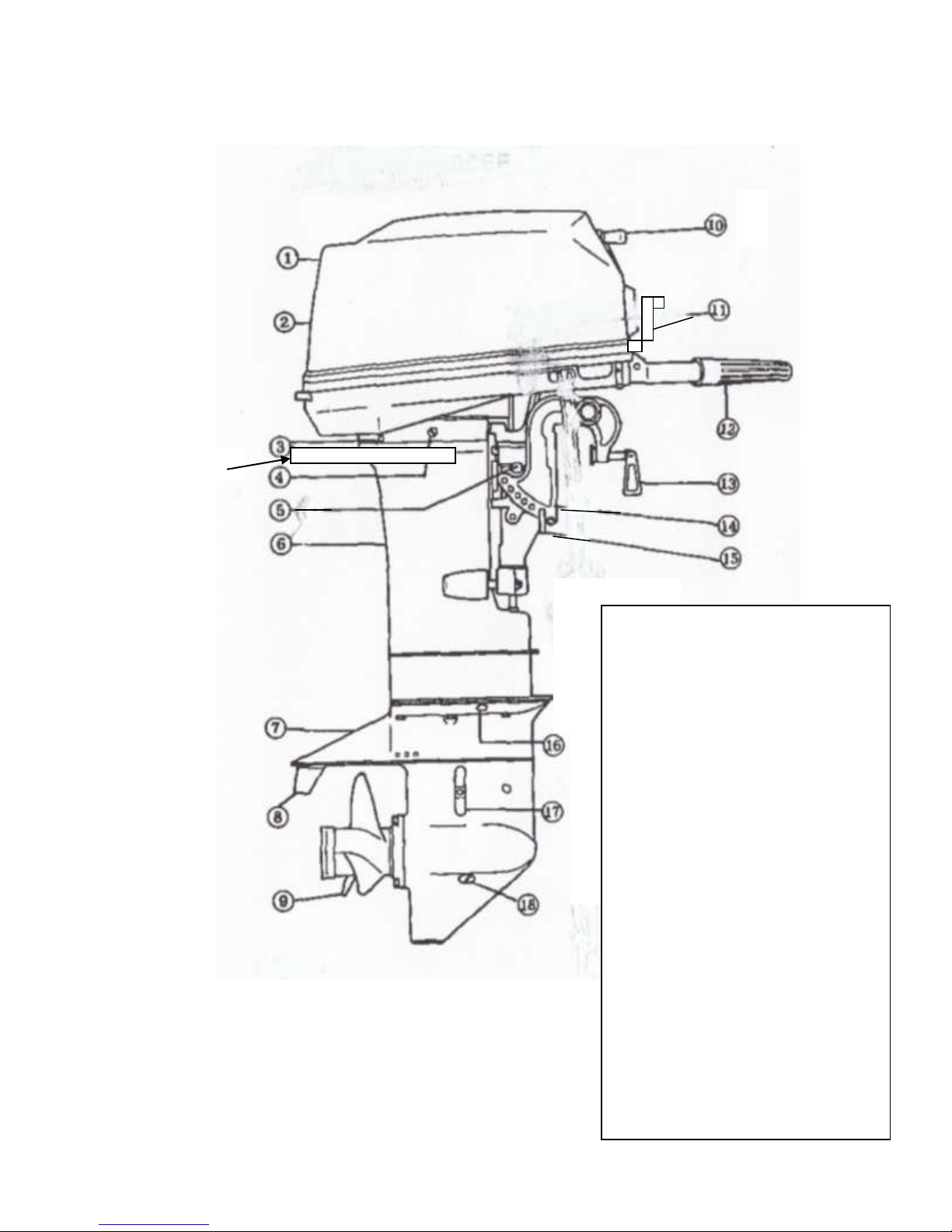
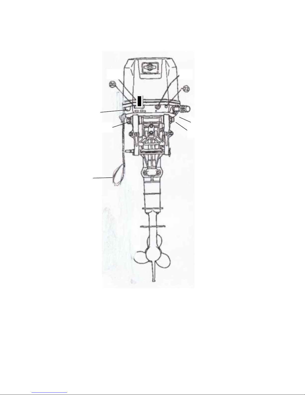
This Raider 40 manual has all parts and assembly data contained herein. It has been
presented to help the user identify parts, identify part numbers, how that part has
been assembled and tools required to repair the part or secure a new part if required.
The Raider is a military only engine and will not be sold to commercial market. It is
submersible and runs multiple fuels. An additive must be placed into JP-5/JP-8 to be
in compliance with EPA.
This manual, Parts/Assembly Manual 40 ES-001-15-2 provides detailed drawings and
part numbers for the Raider outboard motor. This is a supplement to the Service
Manual No. R40ES-001-15-3 that describes in detail how to remove; repair and the
Raider 40.
For background purpose’s the Raider 40 comes from a family of motors that have an
extensive history of reliability and performance and are identical in parts except for
the branding and pricing. These motors are Mercury; Nissan; and Tohatsu.
Supporting Raider with common parts available at local dealers supports a low life
cycle cost for the Government –with worldwide support.
The Mercury, Nissan and Tohatsu outboards are Commercial Off The Shelf (COTS)
engines with a long history of performance and reliability. Raider takes the basic
COTS and modifies the outboards specifically for the military. We have eliminated as
many electrical components as possible and use only the highest reliable mechanical
parts.
Key components of the Raider features a fuel induction system (FIS) which allows
burning of multiple fuels. To go from gasoline to heavy fuels three knobs are turned
on the FIS unit. Second key component is the dewatering system. New heads were
developed with special valves that allows water to be quickly eliminated between the
heads and the pistons. Another key component is a high performance spark plug,
made of stainless steel with a robust spark. This spark plug was developed to allow
submersion without the need to replace spark plugs after submersion. A secondary
start system has been installed that uses a battery to provide quicker starts. The
battery is located under the cowling. A grab rail has been installed to easily carry the
motor and the second is protection of the Raider outboard when dropped. A new
slide plate has been installed in the COTS engine to allow for easier placement on the
rubber inflatable boat, especially in higher sea states.

Raider 40 Manual Military version
1
Parts and Assembly Manual
Section Description Page No.
1 General Precautions, Break in procedures……………. 2
1. Checklist prior to mission
2. Raider Break-In Procedures
2 Raider Engine Overview …………………………………. 4
3 Engine Information ……………………………………….. 5
3.1 Cylinder/Crankcase ……………………………….. 8
3.2 Cylinder/Crankshaft ……………………………….. 9
3.3 Intake Manifold/Fuel Pump ………………………. 10
3.4 Multi-fuel (Throttle Body) Atomizer …………… 11
3.5 Fuel Pump/Oil System …………………………. 13
3.6 Throttle Mechanism ……………………………… 17
3.7 Tiller Handle ……………………………………….. 19
3.8 Magneto ………………………………………….. 21
3.9 Electrical System ……………………………….. 24
3.10 Dewatering System ………………………………. 29
3.11 Recoil Starter ……………………………………… 31
3.12 Starter Lock ………………………………………. 34
3.13 Drive Shaft Housing ……………………………. 39
3.14 Gear Case (Drive Shaft) ………………………… 41
3.15 Gear Case (Propeller Shaft) …………………… 44
3.16 Shifter ……………………………………………… 47
3.17 Transom Bracket ………………………………… 51
3.18 Reverse Lock (Transom Bracket) …………….. 55
3.19 Raider Motor Covering (Cowl) ………………… 56
3.20 Fuel Hose …………………………………………. 57
3.21 Two Raider Motor Configuration …………….. 59
3.22 Tool Kit …………………………………………… 60
4 Engine Details ………………………………………….. 61
4.1 Tune Up procedures …………………….. 61
4.2 Lubrication ……………………………….. 61
4.3 General Service Information ……………. 62
4.3.1 General Equipment Required ……….. 62
4.3.2 Consumables Required ……………… 63
4.3.3 Operational Information …………….. 63
4.3.4 Unit Conversions ……………………… 65
4.3.5 Standard Torque Values …………….. 66
4.3.6 Trouble shooting ……………………….. 68
5 Recommended Spare Parts Kit …………………….. 70

Raider 40 Manual Military version
Section 1. GENERAL PRECAUTIONS
WARNING
Gasoline is extremely flammable and can explode if mishandled.
1. Before performing any service work on the fuel system, read and understand Section 1 - Service
Safety.
2. Before servicing the fuel system, disable the ignition system by removing all spark plug leads to
prevent accidental starting of engine.
3. Fuel leakage can contribute to a fire or explosion. After service work is complete and engine is
fully assembled, always run the engine momentarily to pressurize the fuel system. Then check for
leaks.
4. Never attempt to run the engine with any fuel system component removed or disconnected.
5. Check fuel hoses and other nonmetallic components for indications of damage or deterioration.
Always replace components with authorized factory replacement parts suitable for fuel systems.
6. Clean up fuel spills immediately and store rags in approved containers. Keep drained fuel in
approved containers for proper disposal.
7. When using compressed air to clean or dry parts, make sure the air supply is regulated not to
exceed 25 psi [172 kPa / 1.76 kg/cm2].
1.1 Checklist prior to Mission:
1. Fuel/Oil System 50:1 Mix in bladder
a. Fuels must be premixed.
b. Insure additive is placed in bladder if JP-5 or JP-8 is used (EPA)
2. Electrical System
a. Clean spark plugs, replace if necessary, check gap
b. Check condition of battery
c. Check stop switch operation
3. Control wires and linkage
a. Dewatering linkage works smoothly
b. Check state of linkages
c. Check choke control
4. Recoil starter
a. Check wear or damage on starter rope
b. Check state of ratchet gear
5. Clutch, propeller
a. Check wear or damage on propeller
b. Check condition of split pin
6. Other check points
a. Condition of trim tab (anode)
b. Corrosion or damage
2

Raider 40 Manual Military version
3
1.2 RAIDER BREAK-in PROCEDURES
CAUTION
Failure to follow the Break-In Procedure in Owner’s Manual and special fuel mixture
requirements for break-in may lead to serious engine damage and shortened engine life.
To prevent serious engine damage and ensure long engine life, new engines, used engines with
new powerhead, used engines with newly rebuilt powerhead, and engines coming out of storage
must be run for a period of 10 hours in accordance with the break-in procedure.
First 10 Minutes
• Operate the engine at minimum idle speed
• Verify a steady stream of water from the cooling water check port and idle port on the engine,
indicating the water pump is functioning properly.
Next 50 Minutes (0.16 to 1 Hour)
DO NOT operate the engine above 1/2 throttle.
DO NOT maintain a constant throttle setting. Vary engine speed from 1/4 to 1/2 throttle every 15
minutes.
NOTE
For boats which come onto plane easily, use full throttle to quickly accelerate onto plane; then
immediately reduce throttle to 1/2 and maintain this speed.
Next Hour (1 to 2 Hours)
• Use full throttle to quickly accelerate boat onto plane; then immediately reduce throttle to 3/4 and
maintain this speed.
• At intervals, run engine at 3/4 throttle for 1 - 10 minutes; then return to 1/2 throttle for a cooling
period.
• Vary engine speed every 15 minutes.
• Check for water discharge from cooling water check port
Next Eight Hours (2 to 10 Hours)
• Run engine at 3/4 throttle.
• For short periods of time, run engine at full throttle and then reduce speed back to 3/4 throttle. As
this part of the break-in period progresses, open to full throttle for longer and longer periods of time,
but never longer than 5 minutes.
• Vary engine speed every 15 minutes.
DO NOT exceed the Full Throttle RPM Range of the engine. See Engine Specifications.
After Break-in
• Re-torque cylinder head bolts to specification after engine has been run and cylinder head has
cooled to the touch.

Raider 40 Manual Military version
Section 2. RAIDER ENGINE OVERVIEW
The Raider Outboard 40 horsepower engine has been designed specifically for the
military. It operates on gasoline, Avgas, JP-5, JP-8, kerosene and diesel #2. It is a
simple two-stroke; two-cylinder outboard.
Special Features:
1. Submersible
2. Multi-fuel capability
3. Special transom mount adapter
4. Wrap around grab bar for easier carrying (engine protection)
5. Fuel additives to assist meeting EPA standards when operating JP-5 and JP-8
fuels
Section 3 will describe the Raider 40 outboard in detail. This information includes part
numbers, how to assemble/disassemble each part.
Section 4 will present engine details including Tune-Up procedures, troubleshooting and
special tools required for overhaul and maintenance.
Section 5 provides a list of “recommended spare parts” that supports the Raider 40
outboard and is included in each ”spare parts kit”.
4

Raider 40 Manual Military version
5
Section 3. ENGINE INFORMATION
1. Cowl tilt handle
2. Motor Cover –Upper
3. Cooling Water Check Port
4. Water Plug
5. Tilt Stopper
6. Drive Shaft Housing
7. Anti-Cavitation Plate
8. Trim tab
9. Propeller
10. Starter Handle
11. Shift Lever
12. Throttle Grip
13. Clamp Screw Handle
14. Stern Bracket
15. Thrust Rod
16. Oil Plug (Lower)
17. Water Strainer
18. Oil Plug –Lower
19. Retainer to transom
20. Stop switch
21. Choke knob
22. Electric Starter button
23. Fuel connection
24. Dewatering lever
25. Wrap around grab rail
25

Raider 40 Manual Military version
Front View Raider 40
6
24
23
20
11
19
25
25

Raider 40 Manual Military version
7
Raider 40 Overview

Raider 40 Manual Military version
3.1 CYLINDER/CRANKCASE

Raider 40 Manual Military version
9
Ref.No.
Part No.
Description
Q’ty
Remarks
M40C
1-1
361B01100-
2
CYL BLOCK & CRANKCASE ASSY
1
1-2
393-01137-
0
* NIPPLE
1
1-3
393-01131-
0
* NIPPLE 5.5-5
1
1-4
345-00117-
0
* DOWEL PIN
2
Bearing
1-5
345-01150-
1
* CHECK VALVE ASSY
1
1-6
916129-
0850
* BOLT
1
1-7
916124-
0840
* BOLT
8
1-8
9161F4-
0835
* BOLT
1
1-9
940121-
0800
* WASHER
10
1-
10
345-01111-
0
* DOWEL PIN 6-12
2
1-
11
R61B01001-
1
CYLINDER HEAD
1
1-
12
R50-01093
* CYLINDER HEAD PLATE
1
1-
13
345-01005-
1
CYLINDER HEAD GASKET
1
1-
14
9161F9-
0845
BOLT
10
1-
15
345-01015-
0
WASHER 8.5-19.5-3.2
10
1-
16
9701-1-
1015
SPARK PLUG (BR7HS10)
2
NGK
1-
17
345-01030-
0
THERMOSTAT
1
Mark 52A PRV
1-
18
RH6B01031-
0
DEWATERING VALVES
2
1-
19
R46-01032-
0
DEWATERING FLANGE
1
1-
20
R101F4-
5630
DEWATERING ROD
1
1-
21
338-60218-
2
ANODE
1
1-
22
910103-
0616
BOLT
1
1-
23
345B02301-
2
EXHAUST COVER (OUTER)
1
1-
24
345-02305-
1
EXHAUST COVER GASKET
1
1-
25
9101F4-
5620
BOLT
9
1-
26
98AL-40-
230
HOSE
1
98AL-401000
1-
27
393-01160-
0
CHECK VALVE
1
1-
28
3T5-01133-
0
CLIPφ8
1
1-
29
338-01133-
0
CLIPφ7
1
1-
30
336-06973-
0
CLAMP 6-9.5L
1
1-
31
910103-
6612
BOLT
1
1-
345B05101-
BRACKET
1

Raider 40 Manual Military version
32
0
1-
33
915324-
0825
STUD
2
1-
34
940121-
0800
WASHER
2
1-
35
930121-
0800
NUT
2
1-
36
921503-
0520
SCREW
1
1-
37
930103-
0500
NUT
1
1-
38
309-06972-
0
CLAMP 6.5-47.5P
1
1-
39
345-01303-
1
ENGINE BASEMENT GASKET
1
1-
40
361-05211-
0
STARTER LOCK ARM
1
1-
41
345-05213-
0
THROTTLE LIMITER ARM
1
1-
42
345-05223-
1
ROD SNAP 3.5-2
3
1-
43
345-05221-
1
THROTTLE LIMITER ROD
1
1-
44
345-05222-
1
STARTER LOCK ROD
1
1-
45
930103-
0500
NUT
2
1-
46
346-05234-
0
ROD JOINTφ5
1
1-
47
353-83728-
1
PIN
1
1-
48
951603-
0800
SNAP PIN d=8
1
1-
49
3AA-83719-
0
WASHER 8.5-18-1.6
2
1-
50
941303-
0600
SPRING WASHER
1
1-
51
930103-
0600
NUT
1
1-
52
915324-
0825
STUD
1
1-
53
940103-
0800
WASHER
1
1-
54
345-01015-
0
WASHER 8.5-19.5-3.2
1
1-
55
345-63713-
0
BUSHING 8-14-4
2
1-
56
930403-
0800
NYLON NUT 8-P1.25
1
1-
57
9101F4-
0620
BOLT
1
1-
58
940103-
0600
WASHER
2
1-
59
941403-
1000
WAVE WASHER d=10
1
1-
60
346-63721-
0
BUSHING 6.2-16-5
1
1-
61
345-05224-
0
ROD SNAP 5-2.5
1
1-
62
348-63715-
1
ROD 5-75L
1
1-
63
3B7-05243-
0
BALL JOINT CONNECTOR
1
1-
64
348-63716-
1
THROTTLE ROD
1
1-
65
345-05223-
1
ROD SNAP 3.5-2
1
1-
66
930103-
0500
NUT
1

Raider 40 Manual Military version
11
1-
67
3B7-63733-
0
ROD SNAP 5-2.5
1
1-
68
348-63711-
1
ADVANCER ARM
1
1-
69
910121-
0840
BOLT
1
1-
70
345-63713-
0
BUSHING 8-14-4
2
1-
71
334-66233-
0
WASHER 8.1-16-1.5
1
1-
72
930403-
0800
NYLON NUT 8-P1.25
1
1-
73
345-05223-
1
ROD SNAP 3.5-2
1
1-
74
348-63715-
1
ROD 5-75L
1
for MF/EF
1-
75
346-05234-
0
ROD JOINTφ5
1
for MF/EF
1-
76
3B7-63733-
0
ROD SNAP 5-2.5
1
for MF/EF
1-
77
930103-
0500
NUT
1
for MF/EF
1-
78
361-83728-
0
PIN
1
for MF/EF
1-
79
3AA-83719-
0
WASHER 8.5-18-1.6
1
for MF/EF
1-
80
951603-
0800
SNAP PIN d=8
1
for MF/EF
1-
81
930103-
0600
NUT
1
for MF/EF

Raider 40 Manual Military version
Crankshaft
Crankshaft is not an item that is addressed in the field. Raider Outboard should be sent back to
depot or manufacturer for inspection. Critical concern would be starting the engine with the electric
start prior to dispelling water between piston and heads. It is critical that the dewatering valves are
opened after submersion and pull start is firmly and slowly pulled at a minimum of eight times prior
to using electric starter. Starting engine after submersion without proper dewatering when using
Electric start could damage crankshaft.
Dimension 1 - 2.071 + 0 in [52.6 + 0 mm]
-0.002 - 0.05
Dimension 2 - 1.591 ± 0.002 in [40.4 ± 0.05 mm]
Service Information
4 Connecting Rod Bearing (small end)
1. .0669 in (17 mm)
2. .827 in (21 mm)
3. 1.03 in (27 mm)
4. 0.079 in (2 mm)
Connecting Rod Bearing (big end)
1. 0.984 in (25 mm)
2. 1.260 in (32 mm)
3. 0.787 in (20 mm)
4. 0.138 in (3.5 mm)

Raider 40 Manual Military version
13
3.2 Piston/Crankshaft
Remarks: Crank shaft assembly is difficult to assemble. The
component parts should be purchased as an assembly if possible.

Raider 40 Manual Military version
Ref.No.
Part No.
Description
Q’ty
Remarks
2-1
345-00122-
0
OIL SEAL 25-55-10
1
2-2
345-00125-
0
RETAINER 50-60-1.6
1
2-3
361-00069-
1
CRANKSHAFT SUB-ASSY
1
2-4
361-00031-
0
* CRANKSHAFT A
1
2-5
348-00032-
0
* CRANKSHAFT B
1
2-6
348-00033-
0
* CRANKSHAFT C
1
2-7
348-00034-
0
* CRANKSHAFT D
1
2-8
348-00061-
1
* CRANK PIN
2
2-9
345-00040-
1
* CONNECTING ROD
2
2-10
345-00043-
0
* ROLLER BEARING 25-32-20
2
2-11
345-00045-
0
* BIG END BEARING WASHER
4
2-12
345-00114-
0
* MAIN BEARING 355520
1
Center
2-13
345-00051-
0
* LABYRINTH PACKING
1
2-14
345-00053-
0
* O-RING 2-49.5
1
2-15
951407-
0306
* SPRING PIN 3-6
1
2-16
345-00113-
0
MAIN BEARING 5206
1
Upper
2-17
345-00115-
0
RETAINER 56-66-1.6
1
2-18
945107-
3000
C-RING d=30
1
2-19
345-00116-
0
SPACER 30.2-40-2.3
1
2-20
345-00141-
0
SHIM 31-42
A
2-21
345-00114-
0
MAIN BEARING 355520
1
Lower
2-22
345-00042-
0
ROLLER BEARING 17-21-27
2
2-23
1
3C1-
87130-0
PISTON REPAIR KIT
2
STD
2-24
1
361-00001-
1
* PISTON
1
STD
2-25
345-00021-
1
* PISTON PIN
1
2-26
334-00024-
1
* PISTON PIN CLIP
2
2-27
1
3C1-
87123-0
PISTON RING SET
2
STD
2-28
1
361-00011-
0
* PISTON RING
1
STD 1st

Raider 40 Manual Military version
15
2-29
1
345-00011-
0
* PISTON RING
1
STD 2nd

-10-
Raider 40 Manual Military version
3.3 Intake Manifold/Fuel Pump
Reed Valve and Stopper
Ref.No.
Part No.
Description
Q’ty
Remarks
3-1
915321-
0655
STUD
2
3-2
345B02010-
0
INTAKE MANIFOLD
1
3-3
345-02104-
0
INTAKE MANIFOLD GASKET
1
3-4
345-02105-
0
INTAKE MANIFOLD GASKET
1
3-5
345-02100-
1
REED VALVE ASSY
1
3-6
921521-
7412
SCREW
8
3-7
345-02106-
0
PLATE
1
3-8
910121-
7620
BOLT
1
3-9
345-02103-
0
REED VALVE SEAT GASKET
2
3-
10
9101F4-
5630
BOLT
7
3-
11
915321-
0620
STUD
2
3-
12
930103-
0600
NUT
4
3-
13
941303-
0600
SPRING WASHER
4
3-
14
348-63718-
0
THROTTLE CAM
Ref.No.
3-
15
921503-
0616
SCREW
1
3-
16
346-63721-
0
BUSHING 6.2-16-5
1
3-
17
3C8-66308-
0
WASHER 6-16-1.5
1
3-
18
941403-
1000
WAVE WASHER d=10
1
3-
19
345-02011-
3
CARBURETOR GASKET
1
3-
20
345-67191-
1
PRIME ROD
1
3-
21
345-67192-
0
PRIME ROD
1
3-
22
345-67194-
0
PRIME ROD CONNECTER
1
3-
23
921503-
0408
SCREW
1
3-
24
356-04000-
1
FUEL PUMP ASSY
1
3-
25
334-04004-
0
* PUMP COVER
1
3-
26
9225F2-
6528
* SCREW
3
3-
27
334-04005-
0
* PUMP DIAPHRAGM
1
3-
28
334-04007-
0
* DIAPHRAGM GASKET
1
3-
29
356-04030-
0
* DIAPHRAGM GASKET SET
1

-9-
Raider 40 Manual Military version
3-
30
356-04044-
0
* CHECK VALVE
2
3-
31
921722-
0306
* SCREW
2
3-
32
930222-
0300
* NUT
2
3-
33
346-04901-
2
GASKET
1
Fuel Pump
3-
34
921503-
6640
SCREW
2
3-
35
98AB-50-
160
HOSE
1
F/Connector-Fuel
Filter
98AB-501000
3-
36
98AB-50-
270
HOSE
1
Fuel Filter-Fuel
Pump
98AB-501000
3-
37
98AB-50-
210
HOSE
1
Fuel Pump-
Carburetor
98AB-501000
3-
38
338-02215-
0
CLIPφ10
6
3-
39
346-02230-
0
FUEL FILTER ASSY
1
3-
40
346-02237-
0
* CUP
1
3-
41
346-02235-
0
* GASKET
1
3-
42
346-02234-
0
* FILTER
1
3-
43
930103-
0800
NUT
1
3-
44
940103-
0800
WASHER
2
3-
45
348-02231-
0
PLATE
1
3-
46
345-02411-
0
INTAKE PROTECTION COVER
1
3-
47
345-02415-
0
INTAKE SILENCER COVER
1
3-
48
9101F4-
0616
BOLT
2
3-
49
345-02416-
0
INTAKE SILENCER PLATE
1
3-
50
921503-
5508
SCREW
2
3-
51
345-02417-
1
INTAKE SILENCER LOCK PLATE
1
3-
52
345-67195-
1
BUSHING
1
Note: Lift height of each reed valve and stopper must be within specification.
Used reeds must never be turned over and reused. Reed could break when
returned to service causing serious powerhead damage.
Number of Valves - 40
Strips - 4
Valves/Strip - 3 Valves/Strip
A = Valve –0.236-0.244 in
Height –(6.0-6.2 mm)
B = Gap - 0.0079 in
Valve End/Valve Seat –(0.2 mm)
Other manuals for 40
1
Table of contents
Other Raider Outboard Motor manuals