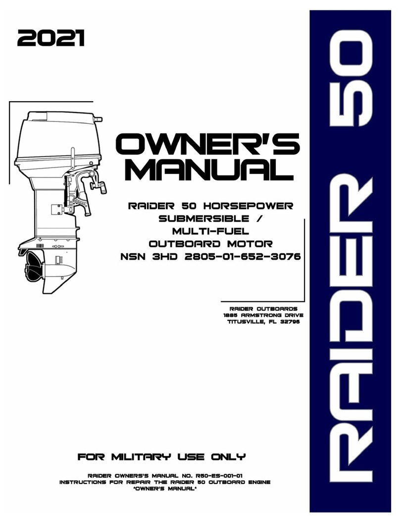
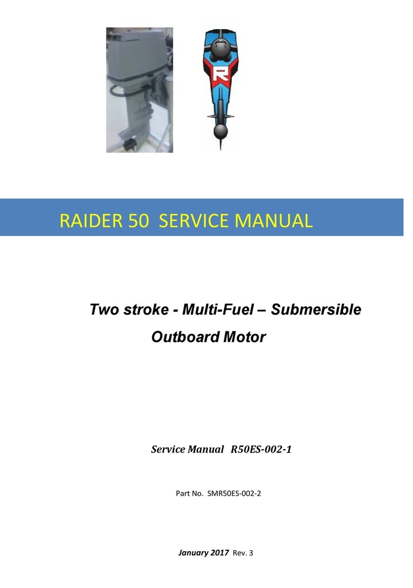
Raider R50-001 User manual

1
2015
Two stroke - Multi-Fuel - Submersible –Air Drop
Outboard Motor
Owner’s Manual R50-
001
This manual has been prepared for the United States military for
Operator knowledge of the Multi-fuel, Submersible Outboard motor designed and manufactured
Under Contract No. N61331•11•C-0008, dated 3/4/11. The data presented in this
Manual was revised as of January 2015 representing the latest revision.
Raider Outboards are not sold to the public.
Raider 50 Owner’s Manual

1
SerialNumberLocation:
Found on top of block –three digits
The Raider R50-001 is a specially manufactured outboard motor for the military for use on Rubber
Inflatable Boats. This motor can be submerged for long periods of time and quickly restarted; operated
on multiple fuels; contains electric start with the battery located under the cowling.
We would like to point out that usage can only be assured on condition
that this manual is read through in
its entirety and the maintenance routines
described later in this manual are followed carefully. Should
difficulty arise
with the engine, please follow the troubleshooting procedures listed at the end
of this
manual.
For any issues
, contact www.raideroutboards.com.
NOTICE: DANGER/WARNING/CAUTION/Note
Before operating your outboard motor, be sure to thoroughly read and
understand this Owner's
Manual and follow all of the instructions shown. Of
particular importance is information preceded by
the words "DANGER,"
"WARNING," "CAUTION," and "Note." Always pay special attention to such
information toensuresaferand trouble-free operation atall times.
YOUR RAIDER OUTBOARD MOTOR
OWNER REGISTRATION AND IDENTIFICATION
This Raider outboard has been purchased by the U.S. Military. Every motor has been delivered under
Form DD-250 which contains individual Serial Nos. www.raideroutboards.com has a record of every
motor delivered.
PRE-DELIVERY CHECK
Insure all physical aspects of the Raider Outboard looks undamaged.
LimitedWarranty
Raider Outboards are fully guaranteed against defective materials and
workmanship for the period
from the date of the Form DD-250 for one year. The limited warranty will not apply to the normal wear
and tear of parts,
adjustments, tune-ups, orto anydamage caused by:
l) Use or operation NOT conforming to the instructions described in this
owner's manual,
2) Parachutes not opening
3) Improper dewatering –Raider must be flushed with fresh water; washed down with soap/water.
4) Damage of an accidents, collisions, contact with foreign materials, or
submersion without cleaning.
5) Growth of marine organisms on motor surfaces that exceeds Submersibility times
6) Any other careless use or operation issues (Battery unplugged when not in use)
7) Normal deterioration.
Failure to observe could result in serious injury or death.

2
The limited warranty does not cover maintenance items. The following items
aresomeexamplesnot
covered by the limited warranty.
Spark
pl
ugs,
anode,
trim-tub,
propeller
,
fuel
filter
,
oil
filter
.
Carbon
brush.
Starter
rope,
shear-pin
,
split-pin,
bolt/nut
·
washer,
wire
cable.
Rubber
goods:
pump
impeller.
Oil
seal,
"O"
-ring,
fuel
pipe,
primer
bulb,
etc.,
vinyl
tube
.
The limited warranty will cover only your Raider Outboard and will not
cover the boat/RIB the Raider is
mounted on, the trailer, equipment, or accessories
associated with the product.
EMERGENCY STOP SWITCH
The stop switch will cut off the engine when the stop switch line is pulled out.
This line can be attached
to the body of the operator, effectively preventing
injuries from the propeller in case he/she falls
overboard.
We
highly r
ecommend
use of stop switch line because it can save the life
of
the
operator
if
something
bad
happens
.
However,
we
would
als
o
like
to
point
out
the
drawbacks
of
the
switch.
Accidental
activation
of
the
switch
(such
as
the
line
being
pulled
out
in
heavy
seas
)
could
cause
passengers
to
lose
their
balance
and
even
fall
overboard,
or
it
could
result
in
loss
of
power
in
heavy
seas,
strong
currents,
or
high
winds.
Loss
of
control
while
mooring
is
another
potential
hazard.
To prevent such hazardous situations, the
500 mm line is coiled and can
be
extended toa full 1,300mm.
WARNINGS
As the operator/driver of the boat, you are responsible for the safety of those
aboard and those in other
crafts around yours. Therefore you should possess thorough knowledge of correct
operation of the
Rubber Inflatable Boat (Wing/Zodiac), its accessories, and the Raider engine. To learn about the correct
operation and maintenance of the engine, please read through this manual
carefully.
It
is very difficult for a soldier standing or floating in the water to take evasive
action should he or she see
a power boat heading in his/her direction, even at a slow speed. Therefore, when your boat is in the
immediate vicinity of people in
the water to be picked up care should be used. A Safety Jet option (jet
pump) from Raider is available and especially useful for training purposes.
SERIOUS INJURY IS LIKELY IF A PERSON IN THE WATER MAKES
CONTACT WITH A MOVING BOAT, GEAR
HOUSING, PROPELLER, OR
ANY SOLID DEVICE RIGIDLY ATTACHED TO A BOAT OR GEAR
HOUSING.
Prior to any mission some individual must be assigned to perform all safety checks and to ensure that
all
lubrication and maintenance instructions are complied with for safe
operation. Periodic maintenance
should be performed. Correct periodic maintenance and good careof this outboard engine will lessen
the
chanceof problems and keepoverall performance of missions successful.
A
CAU
TIO
N
Fail
u
re
to
observe could result
in
mi
nor
personal
i
njury
or
product or
property
damage.

3
SERVICING, REPLACEMENT PARTS & LUBRICANTS
Only qualified personnel should perform maintenance
on the Raider. Training classes can be given or
questions answered by contacting www.raideroutboards.com. Be sure to use genuine Raider parts and
genuine Raider lubricants or
recommended lubricants. 50:1 mix should be synthetic TC-W3 2-cycle oil.
MAINTENANCE
Periodic
inspection at the prescribed intervals is critical.
The Raider motors will be subjected to drops,
submersion and other abuse typical outboards will never receive. The most critical maintenance, after
missions, is to wash down the motor with water and dry. When in salt water it is important to run fresh
water through the system. For long period of time storage a fogging spray can be used. Trouble free
operation cannot be expended unless the engine receives adequate
periodic maintenance.
If
maintenance isperformed periodically, it isnot likely
that acostly overhaul will everbe required.
A maintenance program is outlined later in this User’s Manual.
SUBMERSIBLE - DEWATERING INSTRUCTIONS
Instructions on how to dewater the Raider 50 is located on the top of the cowling. The steps to
dewater after submersion are as follows:
1.
Initiate dewatering valve. This opens valve that releases the water trapped between the
pistons and the heads.
2.
Pull rope starter slowly 8 –10 times. The pistons will displace water out of engine.
3.
Keeping dewatering valve open; press “start” button. The pistons displace final water and
engine begins to start.
4.
If pull start is used, close valve, pull until starts. Primer valve can be pushed to assist
starting.
5.
Close dewatering valve. Engine starts.
6.
If operator detects water in Fuel system; press dewatering valve all the way in, press
rubber bulb on fuel line three times to eliminate fuel which is replaced by new fuel.
7.
Spark plugs rarely need changing; they are designed to operate in wet environment.
EPA LABEL
A label has been applied indicating the Raider 50 does not comply with EPA standards due to
Burning JP-5/JP-8 fuels.
USERS
Raider outboards are designed and built exclusively for the military under National Security
Exemption.
MULTIPLE FUELS
Raider 50 has been designed to operate with multiple fuels: JP-5/JP-8; jet A; kerosene; diesel and bio-
fuels as secondary fuels. Gasoline (minimum 87 octane) is primary fuel. To run heavy fuels each Fuel
Induction System (FIS) has two valves that must be turned to open position. When not using heavy
fuels close valves.

4
CONTENTS
Page
1.
Specifications................................................................................. 6
2.
Names of parts .............................................................................
7
3.
Engine Installation on Rubber Inflatable Boat (RIB)
...................... 8
3-1
Installation- Single Raider ……………………………………………… 9
3-2 Installation –Dual Raiders................................................................ 9
3-3 RIB Transom height
…………………………………………….. 9
3-4 Transom matching with Raider 50
.................................
10
3-5 Attaching the Stern Bracket ................................................. 10
3-6 Propeller Selection..................................................................... 11
3-7 Cowling rear latching
...................................................
11
3-8 Battery
...
.. ..........................................
11
4. Fuel and Engine Oil
...................................................................……. 12
4-1 Raider Fuels................................................................. ……. 12
4-2 Raider 50 Fuel mix ratios ............................................ ……. 13
4-3 Heavy Fuel mix ratios …………………………………………………………
13
5. Running the Raider 50 ...................................................................... ……. 13
5-1
Break-in
…………………………………………………………………………………….
13
5-2
Starting
……………………………………………………………………………….
14
5-3
Manual
Rope
Start …………………………………………………………………..
14
5-4 MotorOperationSteps ………………………………………………………… 15
6. Operation ………………………………………………………………………………………………
20
6-1 Forw
ard/Reverse
R
unning
………………………………
20
6-2
Shallow
Water
Running
……………………………………………………………………………….
20
6-3
Stopping
the
Engine
……………………………………….
21
7. Trim Adjustment ………………………………………………………………………………….. 22
8. Removing and Carrying the Outboard Motor ……………………………………… 24
8-1 Removing the motor for the RIB ………………………………………….. 24
8-2 Carrying the motor ……………………………………………………………….. 24
8-3 Storing the Raider Outboard ………………………………………………… 25
8-4 Trailering the Outboard ………………………………………………………. 25
8-5 Trim Tab Adjustment …………………………………………………………… 26
8-6 Steering Load Adjustment …………………………………………………… 26
8-7 Throttle Grip Turning Load Adjustment ………………………………… 27
9. Inspection and Maintenance ………………………………………………………………. 27
9-1 Pre-mission Inspection Checklist ………………………………………….. 27
9-2 Post Mission maintenance …………………………………………………… 29
9-3 Replacing the propeller ………………………………………………………… 30
9-4 Replacing the Spark Plugs (Pulstar Model SBE 1/10) ……………… 31
Table of contents
Other Raider Outboard Motor manuals