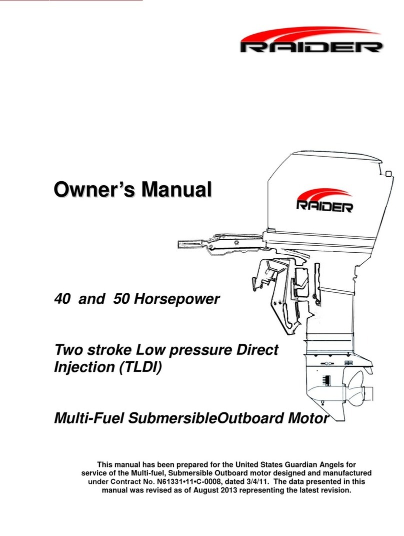
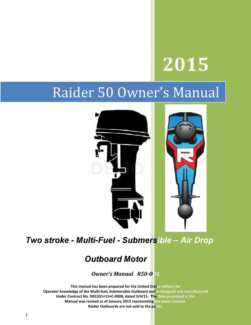
Raider 40 User manual

1
RAIDEROUTBOARD MOTOR
O
Ow
wn
ne
er
r’
’s
s
M
Ma
an
nu
ua
al
l
-
-
4
40
0
H
Ho
or
rs
se
ep
po
ow
we
er
r
Two stroke - Multi-Fuel - Submersible –Air Drop
Outboard Motor
Owner’s Manual R40-ES-001-15-1
This manual has been prepared for the United States military for
Operator knowledge of the Multi-fuel, Submersible Outboard motor designed and manufactured
under Contract No. N61331•11•C-0008, dated 3/4/11. The data presented in this
manual was revised as of January 2015 representing the latest revision.
Raider Outboards are not sold to the public.

Raider Operators Manual R40ES-001-15-1
Contents
1. Your Raider 40 Outboard Motor .....................................................................................................1
a. Limited Warranty ............................................................................................................. 1
b. Serial Number ................................................................................................................... 1
c. Safety/Danger/Warnings/Cautions..................................................................................... 1
d. Features of Raider Outboard............................................................................................. 1
e. Specification Table............................................................................................................. 2
f. Raider Engine Overview.................................................................................................... 3
g. Fuel Induction System - How to change from Gasoline to Heavy Fuels ....................... 4
2. Raider Installation ............................................................................................................................5
a. Handling Engine................................................................................................................ 5
b. Installation of single Engine............................................................................................... 5
c. Installation of Twin Engines................................................................................................ 6
d. Installation of Safety Wire ................................................................................................. 6
e. Transom Height................................................................................................................. 6
f. Propeller............................................................................................................................ 7
3. Raider Running ..............................................................................................................................8
3. Raider Running.................................................................................................................................8
a. Fuels (Multi-fuel)................................................................................................................ 8
b. Raider Break in.................................................................................................................. 8
c. Normal Starting Procedure................................................................................................. 9
d. After Raider Starts/Warm Up.............................................................................................. 9
e. Throttle Friction.................................................................................................................10
f. Shifting .............................................................................................................................10
g. Stopping Raider................................................................................................................11
h. Trim Angle ........................................................................................................................11
i. Trailering...........................................................................................................................11
j. Tilting................................................................................................................................11
k. Trim Tab Adjustment .........................................................................................................12
l. Shallow Water Drive .........................................................................................................12
m. Shallow Water Operation..................................................................................................12
n. Impact Damage................................................................................................................13
o. Special Operating Conditions............................................................................................13
p. Overheating......................................................................................................................14
q. Emergency Starting..........................................................................................................14
r. Pre-Submersion Procedure ..............................................................................................15
s. Dewatering Procedure.......................................................................................................16
t. Post Submersion Procedure..............................................................................................16
4. General Maintenance.....................................................................................................................17
a. Fuel/Oil Requirements......................................................................................................17
b. Removing and Carrying the Raider...................................................................................18
b. Emergency Kit and spare parts ........................................................................................19
d. Corrosion Protection.........................................................................................................19
e. Optional Accessories........................................................................................................19
f. Trouble shooting...............................................................................................................20
g. Storage.............................................................................................................................20
h. Out of Storage Service......................................................................................................21
i. After Submersion Maintenance.........................................................................................22

Raider Operators Manual R40ES-001-15-1
1
1. Your Raider 40 Outboard Motor
a. Limited Warranty
This Raider product is fully guaranteed against defective materials and workmanship for
the period on one year from date on DD-250 form. The limited warranty will not apply to
normal wear and tear of parts, adjustments, tune-ups, or to any damage caused, but not
limited to careless use.
Raider has taken every advantage using non-corrosive materials, high quality and high
reliable parts. This multi-fuel, submersible outboard has been built for ruggedness and
durability to meet war fighter’s needs. After missions the motor should be washed with
soap and water and let dry. Fuel should be run out prior to storage.
The limited warranty does not cover maintenance items. The following items are a few
examples not covered by the limited warranty: spark plugs, Anode, Propeller, Fuel filter,
Oil filter, Starter rope, Shear-pin, Rubber goods, water pump impeller, oil seal, vinyl tub-
ing, and battery.
The limited warranty will not cover the boat the product is mounted on, trailer, equip-
ment, or accessories associated with the product.
b. Serial Number
The serial number is located on the engine block-near heads.
c. Safety/Danger/Warnings/Cautions
Before operating the Raider outboard motor, be sure to thoroughly read and understand
this Users manual and follow all of the instructions shown. Of particular importance in-
formation preceded by the words or symbols draw attention to safety issues. This man-
ual contains information that can help prevent personal injury and damage to equipment.
Understand the following symbols before proceeding:
All motors with electric start will start in gear. User has responsibility to insure Raider is
in neutral before starting. Operator assumes responsibility for this operation.
Battery
Battery must be safely maintained and cannot –under any circumstances-
Take a “fast” charge. A battery “maintainer” is provided and should be
used when motor is being stored. The battery will recharge upon running
of the Raider Outboard. Primary method of start –Pull Starter.
Safety Warning: When replacement parts are required, use genuine Raider parts, or
parts with equivalent characteristics, including type, strength, and material.
*All photographs and illustrations used in this manual may not depict actual models or equip-
ment, but are intended as representative views for reference only.
d. Features of Raider Outboard
- Electric start with battery located under cowling
- Grab handle for easy movement of motor on land and in water
- Transom plates for easy installation onto RIB
- Dewatering lever to dewater both pistons/heads and fuel
- Lightweight –under 150 lbs.

Raider Operators Manual R40ES-001-15-1
2
e. Specification Table
ITEM
RAIDER 40 HP
Overall length
38.18 inches (919 mm)
Overall width
13 inches (330.2 mm)
Overall height
49 inches (1245 mm) (Long Shaft)
Weight
148 lbs. (67kg)
Transom length
20.9 in. (530 mm)
Engine type
2-Stroke Throttle Body
Piston Displacement
493 cc
Bore and Stroke
2.76 x 2.52 (70 mm x 64 mm)
Number of cylinders
2
W.O.T.
5200 –5800 rpm
Exhaust System
Through Hub
Cooling System
Water cooling (Rotary rubber impeller)
Ignition System
C.D. ignition
Starting System
Pull Start; rope backup (electric start with
battery under cowl)
Intake System
Reed Valve
Scavenging system
5-port loop Charge
Exhaust silence system
Add on feature –
Lubrication system
Fuels pre-mixed with additives
Cooling system
Water-cooling
Water temperature control
Thermostat (with pressure relief valve)
Ignition System
Inductive
Gear Reduction
Gear Ratio
13 : 25
1.85
Firing Order
1-2
Spark Plug
NBE1H/10 (stainless steel)
Alternator
12V 280W (Maximum) (13.6 volts regulated)
Battery
Lithium Iron –fully sealed 12 VDC
Trim Angle
4-24 degrees
Trim Angle settings
6 degrees
Maximum tilt-up angle
75 degrees
Transom board thickness
31-70 mm (1.22 –2.76 in.)
Maximum steering angle
80 degrees
Gear shift
Dog clutch (F-N-R) –front location
Electric Start
Push button with safety ring
Throttle Control
Tiller Handle
Fuel Bladder/Tank
Furnished by customer –Mercury connector
JA-8 & heavy Fuels
Additive required-Add to Heavy Fuel Bladder
Gasoline
50 : 1 mix. Add prior to mission in bladder
Engine Oil
Raider provided (synthetic)
Gear Oil
API GL5, SAE#80 to #90 500 ml (16.89 fl.
Oz.) (Synthetic recommended)
Submersibility parameters
66 ft/18 hours; 50 ft./24 hours
Grab Handle
RAMZ and T-Duck Compatible
Dewatering Lever
Push back to open cylinder outlets; hold
back to dewater fuel system
Primer pump
Located in front of Raider

Raider Operators Manual R40ES-001-15-1
3
f. Raider Engine Overview
To operate: Mix 50:1 Two-Stroke Synthetic Oil to gasoline. Hook
up fuel lines. Squeeze fuel bulb to get fuel into motor. Insure bat-
tery is connected. Press start button –or pull start. Dewatering:
slide lever located on left side of motor to rear of engine; pull 8
times slowly; press start button; close dewatering.

Raider Operators Manual R40ES-001-15-1
4
g. Fuel Induction System-Multi-fuel
Multi-fuel Fuel Induction System (FIS) (Operation)
The FIS is styled after a conventional carburetor; the difference is the shape of the air
inlet; shaped to speed up the air which intersects the fuel and between harmonic vibra-
tion of the metering rod the molecules break down to a fine mist. The figure below
shows atomization of the engine fuels prior to entering the combustion chamber.
1
2
3
Fuel Induction System parts
breakdown - critical parts.
The User does not to be con-
cerned about needle and seat be-
coming clogged during mission as
there is none.
Fuel is atomized by shape of
Throttle Body inlet and fuel rod.
1. Turn to right
2. Turn up
3. Open valve for HF
4. Lift Choke up
These provide more fuel to en-
gine. Use Raider additive also.
Gasoline to Heavy Fuels
4

Raider Operators Manual R40ES-001-15-1
5
2. Raider Installation___________________________________________________
a. Handling Engine
The Raider was designed to be carried by a grab rail unit. This
allows the outboard to be moved through submarine hatches and
small areas. The grab rail will protect engine from getting damaged. Be
aware of the sharp propeller when lifting through submarine hatches.
To move engine around shop area, use the Raider outboard stand, supplied
with the delivered engines, that supports engine by transom mount.
b. Installation of single Engine
The Raider has been designed to be released from submarines and air dropped. This in-
stallation will discuss a typical installation –no special operations installation.
Position the outboard engine at the exact center of the stern and mount it against the Rub-
ber Inflatable Boat pad or plate. It is important to keep it centered as much as possible,
Tighten clamp screws by hand DO NOT use tools to tighten clamp screws. Retighten en-
gine clamps after 15 minutes of operation.
WARNING
Most Rubber Inflatable Boats are rated and certified in terms of
their maximum horsepower on the transom. This information is
shown on the boat’s certification plate. Do not equip your RIB with
an outboard that exceeds this limit.
Do not operate the engine until it has been securely mounted on
the boat in accordance with the instructions. Attach safety wire to
boat to avoid losing the motor overboard.

Raider Operators Manual R40ES-001-15-1
6
c. Installation of Twin Engines
When installing two outboard engines, be sure to keep an interval of 470 to 600 mm (18 to
26 inches) between the two engines. Both outboard engines should be at the exact center
of the stern and mount it against the Rubber Inflatable Boat pad or plate. It is important to
keep it centered as much as possible, after centering on transom tighten clamp screws of
both motors by hand. The attachment of a single steering unit for dual mount assembly can
be quickly placed on dual motors for control and a cable inserted from one engine to the op-
posite for single power to both outboards.
d. Installation of Safety Wire
To prevent loss of engine (engines) overboard, attach engine retention
cable that is attached to the Raider outboard to the boat.
e. Transom Height
18 to 26 inches apart
CAUTION
Overheating may occur if Anti-
ventilation plate is at higher level
than the boat as a lack of cooling
water.
Raider motors can be ordered with
fastening holes on each side of the
motor for multiple motor usage.
This allows all motors to be used in
a dual configuration.

Raider Operators Manual R40ES-001-15-1
7
The Raider has been designed to have the anti-ventilation plate at a level 10 to 30 mm
(0.4 to 1.2 inches) below the bottom of the boat as shown above. Be sure the anti-
ventilation plate of the Rader outboard is below the water surface when running with
wide open throttle.
f. Propeller
A propeller must be selected so that the engine rpm measured at wide open throttle while
cruising is within the maximum operating range. In the Raider that range is between 5200
and 5800 rpm.
To ensure optimum performance, the propeller should match the boat type and its load.
Battery
The Raider 40 can be delivered with electric start. It is important to remember the
electric start is a secondary method of starting the outboard. The primary start
is the manual pull start.
The battery is lithium iron and has been sealed. If you notice any issues with the
battery, like overheating, remove and replace the battery. If the battery fails to
start it will recharge after the Raider is in operation. Note: prior to mission the battery
should be placed on the “maintainer” which will indicate if battery is useable or not.
The battery should never be placed on a “fast” charger. The Raider battery has a
Connector compatible with small maintainers. These are available at any Battery/Bulbs
Commercial sales houses. The connectors are made to only go on one way.
When battery not in use –UNPLUG. Acharge can be held for 90 days if packaged in a
RAMZ package.
Replacing the propeller.
A worn or bent propeller will affect engine
performance and may over time cause en-
gine trouble.
1. Pull out the split pin and remove the pro-
peller nut and washer,
2. Remove the propeller by pulling towards
you.
3. Apply grease to the propeller shaft before
mounting the new propeller.
4. Fit the washer, securely tighten the nut
and insert the split pin.

Raider Operators Manual R40ES-001-15-1
8
3. Raider Running
a. Fuels (Multi-fuel)
The Raider can run on jet fuels (JP-5/8), diesel fuel, kerosene, gasoline or gasohol/ethanol.
There are four processes (1. Turn top lever to green; 2) Turn up Secondary to green; 3) turn
counter clock valve –open the entire way; 4) lift knob up, insert lock to completed running
on heavy fuels. If you switch from one fuel to another fuel the Raider engine will operate dur-
ing transition. When using the twin engine configuration it is recommended similar fuels are
used. Additives must be added to fuel prior to missions that use JP-5/8 heavy fuels.
b. Raider Break in
10 Hours. The Raider has provided the break in at the factory. The most critical time in the life of the
Raider engine is the first 10 hours of operation. Correct operation during this break-in period will pro-
long the life of the engine and ensure optimum performance. The procedures we follow are shown
below.
Battery Care and Maintenance
1. Battery should be un-
installed when not in use
and placed on charger.
2. Battery is pluggable into
connector
If battery goes “dead” Raider will
recharge –use pull starter to start
Primer: This is used to push fuel
into the Fuel Induction System

Raider Operators Manual R40ES-001-15-1
9
c. Normal Starting Procedure
Move the tilt/run lever to RUN position. Place engine in normal operating position. Connect the fuel
line connector from the tank to the engine’s fuel connector. Turn fuel line connector onto fuel tank
connector. . if the fuel tank has a manual vent, open it. If you don't, the engine will eventually die
from fuel starvation. Squeeze fuel line primer bulb until firm.
Attach the clip and lanyard assembly to emergency stop switch. Clip must be installed to start engine.
Attach lanyard to secure place on your clothing. An extra emergency restart clip is provided and
stored in the cowling parts tool kit in cowling. Turn twist grip to start position.
Move the twist grip from the start position. Move shift lever to the NEUTRAL position. The engine will
ONLY start in NEUTRAL for manual pull start. ENGINE WILL START IN ANY POSITION WITH BATTERY.
Pull starter handle slowly until starter engages, then pull forcibly for a full rope pull (short or slow pulls
will not provide enough current to the ECU to start).Maintain fuel pressure by squeezing primer bulb until
engine is running. Raider comes with an electric start option.
d. After Raider Starts/Warm Up
Check the water pump is working by looking for a steady stream of water indicates the water pump
is working.
IF the water pump indicator is not discharging a steady stream of water,
STOP the engine when it is safe.
Raider Fuel valve
Stream of
water

Raider Operators Manual R40ES-001-15-1
10
e. Throttle Friction
To increase throttle friction, turn the throttle friction screw clock-
wise. To decrease friction, turn the throttle friction screw counter-
clockwise. DO NOT over tighten.
f. Shifting
To avoid gear case damage:
DO NOT attempt to shift engine from NEUTRAL to FORWARD or REVERSE when
the engine is NOT running. Clutch dogs can align lug-on-lug and result in shift linkage and
lower gear case parts damage. When shifting, always wait until boat has slowed and engine
is at idle speed.
Shift to FORWARD
After engine is running smoothly, turn throttle control to SHIFT position or slower. Move shift
lever to FORWARD/down with a firm, quick motion. DO NOT shift engine with throttle
control advanced beyond the shift position.
Increase Speed: Turn throttle control counterclockwise toward FAST (toward you if
seated in boat next to engine).
Decrease Speed: Turn throttle control clockwise toward SLOW (away from you if seated
in boat next to engine).
Shift to NEUTRAL
Turn throttle control clockwise to the SHIFT position or slower. Move the shift lever to NEU-
TRAL with a firm, quick motion.
When shifting, always wait until boat has slowed and engine is at idle speed.
Shift to REVERSE
Turn throttle control clockwise to the SHIFT position or slower. Move shift lever to REVERSE
When in REVERSE, operate with additional care as the engine has no impact protection if
it hits an underwater obstruction.
Do not operate engine in REVERSE with the tilt/run lever in TILT. Engine may tilt out
of the water, resulting in loss of control.

Raider Operators Manual R40ES-001-15-1
11
g. Stopping Raider
1. Slow engine to idle speed.
2. Move shift lever to NEUTRAL position.
3. Press and hold stop button until the engine stops running.
h. Trim Angle
Engine should be perpendicular to water when boat is underway. This ad-
justment can only be determined by water testing the boat. Set angle ad-
justment for NORMAL boat load.
Move angle adjusting stop rod as shown in picture.
i. Trailering
Place the engine in the normal vertical position. For additional road clearance, move angle adjusting
rod to an outer stern bracket position. Refer to Raider Trim Angle.
DO NOT use the tilt support as a Trailering bracket. The engine should always be resting
on the angle adjusting stop rod when under full power or when trailering.
j. Tilting
DO NOT push down on tiller handle to tilt engine.
Raise Raider
1. Move tilt/run lever to the TILT position.
2. Use tilt grip on engine cover to raise engine. When desired
angle
is reached, move lever to lock position.
Lower Raider
1. Move tilt/run lever to RUN position. Engine will lower to set run position.
Tilt the engine
up entirely

Raider Operators Manual R40ES-001-15-1
12
k. Trim Tab Adjustment
l. Shallow Water Drive
The engines shallow water tilt is controlled by a single lever on the left hand side of the
Raider Outboard.
Disengage Shallow Water Drive
1. Move red tilt/run lever to RUN position.
m. Shallow Water Operation
DO NOT operate engine with gear case dragging on sea bottom. This can result in propel-
ler or water pump damage.
1. Place engine in shallow water drive position. Refer to Shallow Water Drive.
a. DO NOT operate engine in REVERSE with the tilt/run lever in the TILT position.
Engine can tilt up resulting in loss of control.
2. Run at SLOW SPEEDS ONLY. Check water pump indicator often. (Note; Shallow water
drive setting can be adjusted for different boat load conditions.)
3. Before operating in deep water, be sure to lower engine and move tilt/run lever to the
RUN position.
Engine does not have impact protection when operated in the shallow water drive position
or when the tilt/run lever is in the TILT position. Engine will tilt up suddenly if it hits an un-
derwater obstruction.
2. Trim Tab Adjustment
If straight-line direction cannot be achieved, adjust the trim tab located
under the anti-cavitation plate.
-If the RIB veers right, direct the trim tab towards A.
-If the RIB veers left, direct the trim tab towards B.

Raider Operators Manual R40ES-001-15-1
13
n. Impact Damage
Your boat and engine can be seriously damaged by a collision at high or low speeds, while
trailering, or in the water.
If you hit an object, stop immediately and examine the engine for loose mounting hardware
or clamp screws. Inspect for damage to stern and swivel brackets, and components in the
area of impact.Also, examine the boat for damage. Tighten any loose hardware. If collision
occurred in the water, proceed slowly to shore. Before operating again, inspect all compo-
nents.
Failure to inspect for damage can result in sudden, unexpected component failure
and loss of boat control. Uncorrected damage can adversely affect the boat and en-
gine's ability to resist subsequent collisions.
o. Special Operating Conditions
Raider will be used primarily in salt water. It is important to wash down outboard as soon as
possible after missions with fresh water. It is important to run out fuel. During the final burn out
of fuel spray Corrosion Zero mist into throttle body. After drying spray Corrosion Zero into start-
er motor and fine mist over motor.
Sea Water
Fresh water flushing is recommended after use in salt, polluted, or brackish water to
prevent deposits from clogging the cooling passages.
Check gear case anodes for deterioration, and replace if necessary.
During long periods of non-use, tilt engine so that the gear case is out of the water, unless the
temperature is below 32° F (0° C). When removing engine from water, allow cooling system to
drain completely by placing engine in upright position.
Weedy Water
Weeds can block the water intakes and cause engine to overheat. Weeds on the propeller will
cause engine to vibrate.
Run at slow speeds and reverse engine frequently to clear weeds from propeller. Check water
pump indicator often. Remove weeds from propeller and water intakes before operating in clear
water.
Freezing Weather
To avoid engine damage, keep the gear case submerged in the water at all times. Before oper-
ating in freezing temperatures, check gear case lubricant. If leakage is found, gear case seals
will need service.
When removing engine from water, keep the engine in an upright position until the cooling sys-
tem is completely drained.
Water that leaks into gear case or is left in the cooling system can freeze when the engine is
removed from the water. This can cause serious damage.

Raider Operators Manual R40ES-001-15-1
14
p. Overheating
DO NOT operate engine out of water even momentarily.
The engine’s Water Temperature sensor is NOT a warning device.
The Raider does not have an overheat warning. The Raider will not initiate a warning to prevent
powerhead damage. In the event of an overheat situation called “vapor lock” slide dewatering
valve to rear which initiates dewatering of fuel; then squeeze new fuel into engine, close de-
watering valve and start.
If you suspect the engine is overheating or has overheated, STOP the engine only when it is
safe.
When operating the engine, the water intakes must be completely submerged. Make sure the
water intake screens are not installed upside down (ramps must be forward). If upside down,
the engine will overheat. Observe proper transom height and engine trim angle.
When engine is running, the water pump indicator on the starboard side of the lower motor
cover must be discharging a steady stream of water. Check the indicator often, particularly when
operating in weeds, mud, or debris laden water, or at an extreme engine angle.
IF the water pump indicator stops or becomes intermittent, reduce engine speed to an idle when
it is safe. Shift engine into REVERSE and operate at a slow speed for about 10 seconds. This
might clear debris blocking the water intake screens.
IF the water pump indicator is still not discharging a steady stream of
water, SHUT OFF the engine when it is safe. Clean the water intake
screens and water pump indicator. Restart the engine and run at idle.
IF the water pump indicator still does not discharge a steady stream of
water, SHUT OFF the engine when it is safe. DO NOT attempt to operate engine.
IF a steady stream of water is visible from the water pump indicator, check to see if the re-
strictor is installed in the end of the water hose. Without it, the engine and ECU will over-
heat. Continue to run engine at SLOW SPEED ONLY when it is safe until it returns to normal
operating temperature.
If the engine overheats; the cylinder and exhaust cover screws must be re-torqued.
q. Emergency Starting
Make sure the shift lever is at NEUTRAL to prevent sudden boat
movement when the engine starts.
The engine cover is a machinery guard. Prevent injury by keep-
ing hands, clothing, and hair clear of all moving parts. DO NOT
use your hands to turn the flywheel; use recoil starter only.
Prevent electric shock by keeping clear of the ignition coil and
spark plug leads when the engine is being started or is running.
Shock can cause serious personal injury under certain conditions.
Unlatch, then lift and remove engine cover.

Raider Operators Manual R40ES-001-15-1
15
Reach inside the cowling cover. On one side you will find a rope with handle; on the other
side of the cowling you will find a tool that allows the removal of the pull starter.
Use the special service tool to remove the three screws retaining the starter housing.
Lift the pull starter assembly from engine.
Take stored starter rope and wind on the engine flywheel with the knot end
in the grove.
If starter cord is missing or gets broken, it might not be long enough to use
as an emergency starter cord. If in you need an additional rope cut cord
from starter assembly.
Tie a knot to one end of cord. Place knot in the notch on top of flywheel. Wrap cord around
flywheel clockwise as shown.
Follow Normal Starting Procedure.
In your emergency kit you will find tools that will be
required to get engine running. If pull start rope
breaks; electric start does not function; remove three
bolts on pull start unit and remove unit. You will see
flywheel (shown). Tie knot in rope; insert in slot;
Wrap rope around unit and pull until engine starts.
r. Pre-Submersion Procedure
To prevent water intrusion on electronics during submersion:
1. Make sure the inside of all electrical connectors are thoroughly connected.
2. Insure the de-watering valves lever is closed
3. Insure battery is fully charged and re-connected correctly.
4. Insure fuel bladder if fully filled –with 50:1 oil mix and cap tightened.
5. Connect fuel line and pump primer bulb until firm resistance is felt to fill fuel system.
6. If JP-5/8 or heavy fuel insure fuel additive is placed in bladder along with 50:1 mix.
7. Insure the four procedures for heavy fuel have been moved to “green”.

Raider Operators Manual R40ES-001-15-1
16
s. Dewatering Procedure
1. Make sure that the shift lever is in the NEUTRAL position. Open dewatering valve on
side of Raider
2. Hook up fuel line
3. Tilt engine forward into boat (1 to 2 minutes)
4. Open dewatering valves by sliding dewatering lever to back of Raider
5. Let water drain from engine for 2 minutes - pulling engine rope slowly 8-10 times
6. Drop motor to standard running position
7. Pull motor over 10 times slowly with rope pull
8. Push dewatering valve back and hold to push new fuel
9. Keep dewatering valve open
10.Push start button; it will displace remaining water in cylinder
11.When engine tries to start close dewatering valve
12.If no battery available pull until remaining water is displaced using pull starter
13.Start engine –throttle in ½ position
Note: The Fuel Induction System has fuel bowl that can be viewed to determine
Fuel is present. Also spark plugs should not need changing after being
submersed.
You MUST run the engine after performing the Dewater Procedure to dissipate internal mois-
ture. In other than mission situations, run engine under normal operating conditions for 15 to 40
minutes.
During mission situations, operate as conditions require.
t. Post Submersion Procedure
After your mission, the Raider must be prepared to be returned to nonuse or prepared for your
next mission.
If the RAIDER is re-submersed after your mission and it cannot be serviced, keep it submersed
to avoid prolonged exposure to the atmosphere, until it can be serviced. If the Raider is brought
on deck and it can’t be operated or serviced, keep it submerse in fresh water, but get it prepared
for your next mission as soon as possible.
If the RAIDER can be operated on deck, dewater the engine following the procedures in De-
water Procedure; operate the engine for approximately five minutes at full operating tempera-
ture with fresh water. Remove the upper cover to allow the powerhead and other components to
air dry. Whenever possible after use or submersion in sea water, wash entire engine with fresh
water to remove salt deposits and wipe down with a dry cloth. Spray the entire powerhead with
an Anti-Corrosion Spray- recommended –Corrosion Zero or equivalent. Follow this procedure to
prepare the Raider for your next mission.

Raider Operators Manual R40ES-001-15-1
17
4. General Maintenance
General Safety Warnings
When replacement parts are required, use genuine Raider parts or parts with equivalent
characteristics including type, strength, and material. Failure to do so may result in
product malfunction and possible injury to the operator and/or passengers.
To prevent possible eye injury, always wear SAFETY GLASSES while servicing the unit.
Always read and follow safety related precautions found on containers of hazardous
substances like parts cleaners, primers, sealants, and sealant remover.
The engine cover is a machinery guard. Use caution when conducting tests on running
engines. Do not wear jewelry or loose clothing. Keep hair, hands, and clothing away from
rotating flywheel.
Replace any locking fastener (locknut or patch screw) if it’s locking feature becomes
weak. Definite resistance to tightening must be felt or locking fastener is not suitable for
continued use. Replace only with authorized replacement part or equivalent.
a. Fuel/Oil Requirements
Mix Fuel to Oil ratio: 50 - 1
Oil Requirements: Recommend - Raider Oil additive.
Above 30° F Biodegradable Outboard Oil
Below 30° F 100% Fully Synthetic 2-Cycle Engine
Recommended Fuel: Gasoline,
Jet A, - Heavy Fuels JP5 or JP8, kerosene, diesel #2
Additive required to reduce smoke/emissions and carbon
build up in Raider. Use in addition to Raider 2-Stroke oil.
When using JP-5/8 fuels you must use
both Raider Two-Stroke mix AND the
Raider fuel supplement additive.

Raider Operators Manual R40ES-001-15-1
18
b. Removing and Carrying the Raider
Snap out handles are located on
each side of the Raider for ease
of movement. These handles
can remain extended to lay mo-
tor on its side.
Movement and storage of Raider should be done on stand. The Raider stand was devel-
oped for durability and excellent height to work on outboard. The Raider cart also provides
protection for the outboard as the cart extends over key areas of the outboard.
Other manuals for 40
1
Table of contents
Other Raider Outboard Motor manuals