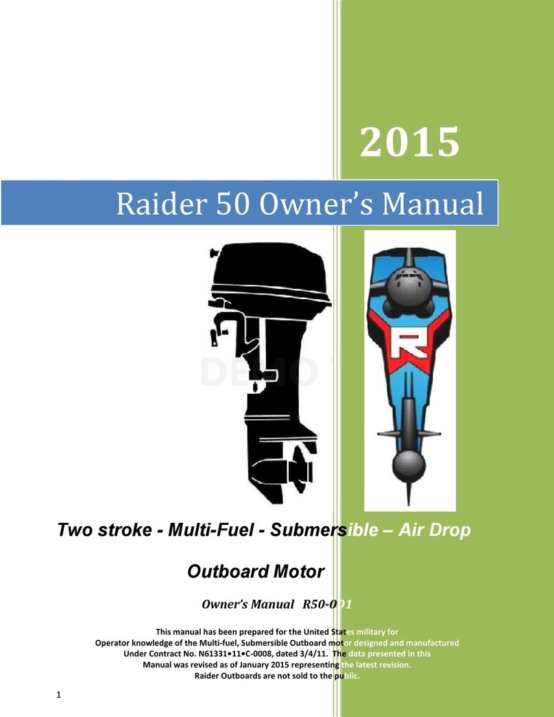
Raider 50 User manual

Two stroke - Multi-Fuel –Submersible
Outboard Motor
Service Manual R50ES-002-1
1
RAIDER 50 SERVICE MANUAL
January 2017 Rev. 3
Part No. SMR50ES-002-2

GB
Introduction
Before reading this manual
This service manual provides information that is needed for inspection, service and repair of the
Raider 50 outboard motor. For information about operation of the products that are not
described in this document, refer to the owner’s manual (Part No. OMR50ES-002). For our
users we have built the best outboard motor for long term, it is essential for the maintainer to
prepare the outboard prior to the mission. To ensure this, the maintenance and service have to
be done properly by a service technician with fundamental knowledge and skills. This manual
is utilized so that our operators can always use their outboard motor with full satisfaction.
Raider Outboards are a Commercial Off The Shelf (COTS) based upon the Tohatsu MWX50D2
which uses the heavy duty gear case. Modifications to this COTS product are detailed in this
service manual.
Safety Information
Safety Statements
The following safety statements are found throughout this manual and indicate information
which, if ignored, could result in fatal safety hazards or property damage.
Take Notice.

GB
About this manual
Composition and use of this manual
This service manual is designed so that service personnel are able to perform repairs
correctly. Understand the following subject matters well for efficient service and repair.
1 Each chapter begins with the introduction of special tools that are used for the work described.
2 Parts that are serviced in each chapter and their details are presented by using a component composition
diagram.
3 Fastening torques are described in the component composition diagram. In the body text are critical
points of the applicable work.
4 Pictograms indicate that there is an important work instruction for the relevant parts. It also shows the type
of lubricant and its application point(s).
5 The component composition diagrams describe the names of the parts, the number of pieces of the parts
used, size of fasteners and special notes.
6 Specific works are described in detail by using illustrations and adding advice on the work.

This manual uses the International System of Units (SI) unit system for the pressure, force (load),
torque and stress. This manual adopts the international unit construction system (SI unit system)
followed by the conventional imperial and metric systems enclosed by ( ) and [ ] as described
below.
<Reference>
What is the SI unit system?
Although the measurement unit is standardized mostly with metric system in the world, the metric
system includes different kinds of unit systems. Though the metric system was established expecting
that a single unit system is used in the world, various physical units were established later, resulting in
branching the metric system in different unit systems. The new unit system is called International System
of Units because it was established for the purpose of unifying the different unit systems.
Since the metric system was initially established in France, and International Bureau of Weights
and
Measures (IBWM) is located in Paris, General Conference of Weights and Measures (GCWM)
passes a resolution of the international unit system as "Systéme International d'Unités (French)" that
is abbreviated as
SI unit .
For example, conventional metric system uses the unit of mass (kg) and
unit of force (kg or kgf) without
discriminating them, but the SI unit system uses, for example, kg as the
unit of mass, and N as the unit of force, aiming to apply a kind of unit for a kind of physical quantity.

Corrosion Zero

’
1.Service Information
1.
Identification
(Engine Serial Number)... ........
.1-2
2.
Work Safety........................
.1-2
1) Fire Prevention...................................
.1-2
2) Ventilation...........................
.1-2
3) Protection ............................ 1-2
4) Genuine Parts ... .................
.. 1-2
5) Tools ... ....................
... 1-4
6) Recommendations on Service .... 1-4
7) Cautions in Disassembling and
Assembling Components ...... 1-6
3.
Tools and Instruments ...........
.1-8
1) Test Propeller ... ................
.. 1-8
2) Measuring Instruments ... .........
.1-8
3) Special Tools ... .................
.. 1-10
4.
Pre-delivery Inspection ...... 1-16
1) Tiller Handle..................................
.. 1-16
2) Gear Shift .................................
... 1-16
3) Gear Oil ... ......................
.1-16
4) Fuel and Fuel Line ........................
.. 1-18
5) Installation of Outboard Motor
(Rigging)... .....................
.1-18
6) Propeller Selection ........................
.. 1-20
7) Cooling Water Check Port
.. 1-22
8) Trim Tab ... .......................
.1-22
5. Break-In Operation.....................
.. 1-24
6.
Test Run ... ....................
.. 1-24
7.
Checks After Test Run...........
... 1-24
2.Service Data
1. Outboard Dimensions .....................
.2-2
1) Body dimensions... .................
.2-2
2) Clamp Dimensions ... ........
... 2-4
2.
Cooling Water System Diagram
... 2-6
3. Specifications ............................
.. 2-8
4. Maintenance Data ... .......
... 2-12
5. Torque Specifications... .......
.2-16
6. Sealant And Lubricant ...........
... 2-17
3.Maintenance
1. Special Tool ............................
... 3-2
2. Inspection Schedule ... .......
.. 3-2
3. Inspection Items ..................
.3-6
1) Inspection of Top Cowl ... .........
.3-6
2) Inspection of Fuel Tank ... .........
.3-6
3) Fuel System ....................
... 3-8
4) Inspection of Cooling Water Passage . 3-10
5) Flushing with Water ... ........
.. 3-10
6) Inspection of Compression Pressure
.3-14
7) Inspection of Spark Plugs
.. 3-18
8) Inspection of Thermostat ...... 3-20
9) Adjustment of Throttle Cable .... 3-22
10) Ignition Timing Adjustment ..... 3-24
11) Carburetor Synchronization..... 3-26
12) Pilot screw adjustment ... .........
.3-30
13) Replacement of Gear Oil ...... 3-32
14) Inspection of Gear Case (for leakage) .. 3-34
15) Inspection of Propeller ... .........
.3-34
16) Replacement of Anode.............
.3-36
17) Greasing...........................
.3-38
4.Fuel System
1. Special Tools ..................
... 4-2
2. Parts Layout ............................
... 4-4
Fuel line ... ..............................
.4-4
Intake Silencer • Carburetor ... ..........
.4-6
3. Carburetor Inner Passages .... 4-10
1) Idling Passage..................................
.4-10
2) Off-Idle Passage........................
... 4-12
3) High Speed Passage........................
.4-14
4) Choking Passage
(#2 and #3 carburetor) .............
.4-16
4. Inspection Items....................
... 4-18
1) Removing Carburetors.............
.4-18
2) Disassembling Carburetors
.4-20
3) Cleaning and Inspection ...... 4-22
4) Inspection of Fuel Pump and
Needle Valve .....................................
.4-24
5) Disassembly and Inspection of Fuel
Pump ... ...................
.. 4-34
6) Assembly of Fuel Pump ...... 4-26
7) Inspection of Fuel Connector .... 4-26
8) Inspection of Fuel Filter .............
... 4-26
9) Assembling Carburetors ...... 4-28
10) Inspection of Float Height
.. 4-30
11) Installing Carburetors .......................
.4-30
5.Power Unit
1. Special tools ... ..............
... 5-2
2. Parts Layout ............................
... 5-4
Engine ... ...........................
.5-4
Magneto...............................................
... 5-6
Electric Parts................................................
.5-8
Recoil Starter... .......................
.5-10
Intake Manifold · Reed Valve ...... 5-14
Throttle...............................................
... 5-16
Cylinder Crank Case..........................
... 5-20
Piston & Crank Shaft .........................
... 5-24
3. Inspection Items ... ...............
.5-26
1) Removing Power Unit .............
.5-26
2) Removing Flywheel ............
.. 5-32
3) Removing Electric Parts ...... 5-32
4) Removing Throttle Link..............
... 5-34
5) Removing Intake Silencer and
Carburetors.....................................
.. 5-38
6) Removing Intake Manifold and
Reed valves....................................
.. 5-40
7) Inspection of Reed Valve Ass'y ... 5-40
8) Removing Thermostat and
Engine Anode.....................................
.5-42
9) Removing Cylinder Head / Head Cover .. 5-46
10) Inspection of Cylinder Head
.5-48
11) Removing Exhaust Cover
.. 5-50
12) Inspection of Exhaust Cover
.5-50

13) Removing Crank Case... .........
.5-52
14) Removing Pistons... .........
... 5-54
15) Disassembly of Crank Shaft
.5-56
16) Inspection of Crank Shaft
.. 5-56
17) Inspection of Engine Parts ..... 5-60
18) Inspection of Pistons.........................
.5-62
19) Assembling Crank Shaft ...... 5-68
20) Installing Needle Bearing and Pistons... 5-70
21) Assembling Power Unit Parts .... 5-74
22) Assembling Crank Ass'y and
Crank Case.....................................
.. 5-76
23) Assembling Exhaust Cover Parts .. 5-78
24) Assembling Cylinder Head Parts
.. 5-80
25) Assembling Coil Bracket Parts
... 5-82
26) Assembling Crank Case Head Parts
.. 5-82
27) Installing Reed Valve, Intake
Manifold and Intake Silencer. .... 5-84
28) Attaching Recirculation Hoses
... 5-88
29) Installing Throttle Link ............
.5-90
30) Installing Electric Parts............
.5-92
31) Installing Flywheel............
... 5-92
32) Installing Power Unit............
.. 5-94
33) Disassembly of Recoil Starter.... 5-96
34) Inspection of Recoil Starter ..... 5-98
35) Assembling of Recoil Starter .... 5-98
6.Lower Unit
1. Special Tools ... ..............
... 6-2
19) Removing Drive Shaft Ass’y
.6-52
20)
Disassembly of Drive Shaft Ass’y .. 6-54
21)
Inspection of Drive Shaft ...... 6-54
22)
Inspection of Pinion (B) Gear .... 6-54
23) Assembly of Drive Shaft Parts
... 6-56
24) Removing Forward (A) Gear Ass’y
.6-60
25) Disassembly of Forward Gear (A) Gear
.. 6-60
26)
Inspection of Forward (A) Gear ... 6-62
27) Assembly of Forward (A) Gear Parts
.. 6-62
28)
Disassembly of Gear Case ..... 6-66
29)
Inspection of Gear Case ...... 6-68
30)
Assembly of Gear Case Parts.... 6-70
31) Measurement of Pinion (B) Gear Height
and Shim Selection ... ........
.. 6-76
32) Measurement of Back Lash between
Forward (A) and Pinion (B) Gears and
Shim Selection ... ................
.6-80
33) Measurement of Back Lash between
Pinion (B) and Reverse (C) Gears and
Shim Selection ... ................
.6-88
34)
Assembly of Lower Unit Parts.... 6-92
35)
Assembly of Pump Case ...... 6-94
36) Attaching Clutch Cam Ass’y
.6-96
37) Measurement of Propeller Shaft Play and
Selection of Washer Thickness ... 6-98
38) Installation of Lower Unit
.. 6-100
2. Parts Layout............................
... 6-6
Gear Case (Drive Shaft, MX50) ... .........
.6-6
Gear Case (Drive Shaft, MWX50)...... 6-14
Gear Case (Propellor Shaft, MWX50) .... 6-18
3. Inspection Items ..................
.6-22
1) Draining Gear Oil ... .........
... 6-22
2) Removing Propeller ... .........
.. 6-22
3) Removing Lower Unit........................
.6-24
4) Disassembly of Cam Rod
.. 6-26
5) Inspection of Clutch Cam...... 6-26
6) Assembly of Clutch Cam Parts
... 6-28
7) Removing Water Pump..............
... 6-30
8) Inspection of Water Pump
.. 6-32
9) Inspection of Water Pipe ...... 6-32
10) Disassembly of Water Pump Case
(Lower) ..............................................
.6-34
11) Assembly of Water Pump Case
(Lower) ..............................................
.6-34
12) Removing Propeller Shaft Housing
Ass’y...............................................
.. 6-36
13) Disassembly of Propeller Shaft Housing
Ass’y...............................................
.. 6-38
14) Inspection of Propeller Shaft Housing
.. 6-42
15) Assembly of Propeller Shaft Housing
.. 6-42
16) Disassembly of Propeller Shaft Ass’y
.. 6-46
17) Inspection of Propeller Shaft Ass’y
.6-48
18) Assembly of Propeller Shaft Ass’y .. 6-50
7.Bracket
1. Parts Layout ............................
... 7-2
Drive Shaft Housing ....................................
.7-2
Bracket Manual Tilt... .................
.. 7-4
Manual Tilt...............................................
.. 7-8
Tiller Handle ... ........................
.7-10
Bottom Cowl • Shift ... .................
.7-12
TOP COWL ... ........................
.7-16
2. Inspection Items....................
... 7-18
1) Inspection of Throttle Cable
.7-18
2) Removing of Tiller Handle
.. 7-18
3) Installation of Tiller Handle ..... 7-20
4) Removing Bottom Cowl.............
... 7-24
5) Removing Drive Shaft Housing ... 7-26
6) Disassembly of Drive Shaft Housing
.. 7-28
7)
Inspection of Drive Shaft Housing
... 7-32
8) Assembly of Drive Shaft Housing Parts .. 7-34
9) Assembling Rubber Mounting.... 7-38
10) Assembling Extension Housing ... 7-40
11) Removing Steering Shaft Arm
... 7-42
12) Installing Steering Shaft.............
... 7-44
13) Disassembling Clamp Bracket
... 7-46
14) Assembling Clamp Bracket ..... 7-48
15) Disassembling tilt mechanism.... 7-50
16) Assembling tilt mechanism ..... 7-52
8.Electrical System
1. Special Tools ... ..............
... 8-2
*What’s Peak Voltage......................
.8-2

Merit of adoption of
peak voltage measurement ... ......... 8-2
Recommended tester... .................... 8-2
2. Parts Layout ................................. 8-4
Magneto ....................................... 8-4
Electric Parts (C.D. Unit) ................ 8-6
3. How to use Peak Voltage Adapter .8-8
Attention of measurement ... .......... 8-8
Measurement procedure: ... ........... 8-8
4. Inspection date ... .......................... . 8-10
Resistance test reference.............. .8-10
Peak voltage out put test reference
... 8-10
5. Inspection Items....................... ... 8-12
1) Inspection of Ignition and spark ... 8-12
2) Inspection of Plug Cap Terminal
.. 8-12
3) Inspection of Ignition Coils ..... 8-14
4) Inspection of Pulser Coil ...... 8-14
5) Inspection of Exciter Coil .. 8-16
6) Inspection of C.D.unit .............. .8-16
7) Inspection of Stop Switch .. 8-18
9.Troubleshooting
1. Troubleshooting Chart ... ............... . 9-2
2. Power Unit ... ................................ . 9-3
1 Engine will not start ... ............. .. 9-3
Starting System ........................9-3
Ignition System .........................9-4
Fuel System ...................... ... 9-6
Compression Pressure ............ . 9-7
2 Engine starts but stalls soon.........................
... 9-8
Fuel System ...................... ... 9-8
Ignition System .........................9-9
Compression Pressure........... . 9-10
3 Idle engine speed will not stabilize..... 9-11
4 Rapid opening of throttle fails acceleration... 9-12
5 Gear shifting cannot be made normally.
..
9-13
10. Safety Jet - Optional

INDEX
1
Service Information
2
Service Data
3
Maintenance
4
Fuel System
5
Power Unit
6
Lower Unit
7
Bracket
8
Electrical System
9
Troubleshooting
10
Wiring Diagram
11
Safety Jet

ES
1
Service Information
1. Identification
(Engine Serial Number) .....
1-2
2. Work Safety ... .............
.. 1-2
1) Fire Prevention... ........
... 1-2
2) Ventilation ... ...............
…1-2
3) Protection ... ...............
.. 1-2
4) Genuine Parts ... ........
... 1-2
5) Tools ........................
.
1-4
6) Recommendations on Service ..
1-4
7) Cautions in Disassembling and
Assembling Components
.
1-6
3. Tools and Instruments ..... 1-8
1) Test Propeller........................
... 1-8
2) Measuring Instruments
.. 1-8
3) Special Tools ........................
... 1-10
4. Pre-delivery Inspection ..... 1-16
1) Tiller Handle ... .................
.1-16
2) Gear Shift ... ...............
.. 1-16
3) Gear Oil ... ................
... 1-16
4) Fuel and Fuel Line .......................
.1-18
5) Installation of Outboard Motor
(Rigging) ....................................
.. 1-18
6) Propeller Selection ... .........
.1-20
7) Cooling Water Check Port .... 1-22
8) Trim Tab ...................................
.. 1-22
5. Break-In Operation ...........
.1-24
6. Test Run........................
.1-24
7. Checks After Test Run ..... 1-24

Service Information
1. Identification (Engine Serial Number)
Engine serial number is stamped on the front left hand side
of the motor on
stainless steel..
1 Serial Number
50D2
1 2
SERIAL No.
3
RATED POWER
36.8 kW
FULL THROTTLE RANGE
5150
-
5850
r / min
MASS
- kg
2. Work Safety
1) Fire Prevention
Gasoline is hazardous material and very flammable. Do not
handle gasoline near ignition source such as spark or static
electricity.
2) Ventilation
Exhaust gas or gasoline vapor is hazardous. Be sure to
ventilate well when working indoors.
3) Protection
Wear a pair of goggles, working gloves and safety shoes
to protect skin from chemicals and oils and eyes from
particles generated by grinding or polishing. Avoid contact
of oil, grease or sealing agent to the skin. In case of
exposure to such matters, wash away with soap or warm
water immediately.
4) Genuine Parts
Use parts and/or chemicals that are genuine Raider
items or
recommended.
Serial #

Service Information
7) Cautions in Disassembling and
Assembling Components
(1) Secure outboard motor to dedicated stand firmly.
(2) Take special care not to scratch painted surfaces or
mating surfaces of cylinder and crankcase.
(3)
Replace parts such as packings, gaskets, O rings, oil
seals, spring pins or split pins with new ones after they are
removed. Replace deformed snap rings with new ones.
(4) When replacing parts, be sure to use genuine parts. For
fluids such as gear oil, use genuine product.
(5) Be sure to use special tools that are specified, and
perform the work properly.
(6)
When reassembling parts, use their mating marks. For
parts without mating marks, simple marking makes
reassembling easier. Use applicable parts list for
reference.
(7) Clean individual parts that have been removed, and check
their condition.
(8) When assembling, be careful of the fit, repair limits, air-
tightness, clogging of oil holes for oil feeding or greasing,
packings, wirings, pipings and other detailed parts. For the
components that use many bolts and nuts such as cylinder
head or crank case, tighten the fasteners in the order
shown by the numbers to prevent uneven tightening. If the
numbers are not shown, tighten the fasteners in diagonal or
clockwise order from inner ones to outer ones evenly to
specified torque. In either case, tighten the fasteners to the
LIT
LIT specified torque in two or three steps. (Reverse the order
when disassembling.)
(9) When installing bearings, face the flat (numbered) side to
the special assembling tool.
(10)
When installing oil seals, be careful not to scratch the
surface of the lip that contacts with the shaft, and install
them in correct orientation. Apply recommended grease to the
lip before installation.
1
(11) When applying liquid sealant, take care to use sparingly.
Excessive application may be oozed out, adversely
affecting interior of the crankcase. Use adhesive after
thoroughly reading the instructions.
(12) When servicing power unit, use of wooden work board
2
makes the work easier.

Service Information
RO
3. Tools and Instruments
1) Test Propeller
2) Measuring Instruments
Raider 50
Test Propeller :
P/N. 3F3-64110-0
Outer : 236mm
Width : 45mm
Rotational speed at WOT
Model (Wide Open Throttle) (r/min)
Raider 50 5000-5800
For the following measuring instruments, use commercially available ones.
Circuit tester ( Resistance : 1Ω, 10Ω, 10 kΩ, AC voltage : 30 to 300V, DC voltage : 30V, Internal voltage 3V or less )
Vernier calipers ( M1 type, 300 mm )
Micrometer ( minimum graduation of 0.01, outer, 0 to 25 mm, 25 to 50 mm, 50 to 75 mm )
Cylinder gauge ( 4 to 6 mm, 10 to 25 mm, 25 to 30 mm, 50 to 75 mm )
Ring gauge ( ø5.5, ø16, ø25, ø30, ø61)
Dial gauge ( minimum graduation of 0.01 )
Thickness gauge ( 0.03 to 0.3 mm )
V block
Surface plate ( 500 mm x 500 mm )
Dial gauge magnet base or dial gauge stand
Test Propeller is used in shop to instrument
Raider outboard motor.

Service Information
3) Special Tools
1 2 3 4
Spring Pin Tool A Spring Pin Tool B
P/N. 345-72227-0 (ø3.0) P/N. 345-72228-0 (ø3.0) Compression Gauge Tachometer
P/N. 369-72217-0 (ø3.5) P/N. 369-72218-0 (ø3.5) P/N. 3AC-99030-0 P/N. 3AC-99010-0
Removing spring pin
Installing spring pin Measuring compression
pressure
Measuring engine revolution
speed
5 6
3T1-72781-0
7
3B7-72785-0
3B7-72783-0 3C7-72783-0 940191-0800 3B7-72784-0
Vacuum/Pressure Gauge Flywheel Puller Kit Piston Pin Tool
P/N. 3AC-99020-0 P/N. 3T1-72211-0 P/N. 345-72215-0
Inspecting pressure Removing or attaching flywheel Detaching and re-attaching
the piston
8 9 0
q
Piston Ring Tool Eye Bolt (Powerhead Lift Ring) Universal Puller Plate Roller Setting Piece
P/N. 353-72249-0 P/N. 3T9-72212-0 P/N. 3AC-99750-0 P/N. 3LC-72216-0
Detaching and re-attaching
the piston rings
Used to hook power unit when
hanging
Removing main bearing and
reverse (C) gear bearing Installing roller bearing
w e r t
25 28
Piston Pin Tool
Propeller Shaft Housing Puller Ass'y
Bevel Gear B Nut Wrench Bevel Gear B Nut Wrench
P/N. 3LC-72215-0 P/N. 3A3-72259-0 MX50:P/N. 346-72231-0 P/N. 353-72231-0 (MWX50)
Installing piston pin Removing propeller shaft
housing
Removing or attaching pinion
(B) gear nut
Removing or attaching pinion
(B) gear nut

Service Information
y u i o
ø31.5 x ø25 x H32
Roller Bearing Attachment
Bevel Gear Nut Socket Driver Rod Center Plate MX50:P/N. 3MC-99710-0
P/N. 346-72232-0 P/N. 3AC-99702-0 P/N. 3AC-99701-0 MWX50:P/N. 3LC-99710-0
Removing or attaching pinion
(B) gear nut
Used in combination with center
place and various attachments
Removing or installing propeller
shaft housing bearing
Used in combination with driver rod and center plate
Attaching propeller shaft housing needle bearing
p a s d
Roller Bearing Puller Kit
Bevel Gear Bearing Install Tool Roller Bearing Press Kit MX50:P/N. 3C8-72700-0 Slide Hammer Ass'y
P/N. 3C8-72719-0 P/N. 3LC-72900-0 MWX50:P/N. 3B7-72700-0 P/N. 3AC-99080-0
Installing forward (A) gear
Removing or attaching gear case
Removing or attaching gear case and
Removing forward (A) gear
bearing needle bearing propeller shaft housing needle bearing bearing outer race
f
Bevel Gear Bearing Puller Ass'y
g
3B7-72731-0
3B7-72732-0
3B7-72733-0
h
Shimming Gauge
j
MX50:P/N. 3A3-72755-0 Bearing Outer Press Kit MX50:P/N. 3C8-72250-0 Thickness Gauge
MWX50:P/N. 3B7-72755-0 P/N. 3B7-72739-1 MWX50:P/N. 353-72250-0 P/N. 353-72251-0
Removing forward (A) gear bearing
outer race
Attaching forward (A) gear
bearing outer race
Adjusting pinion (B) gear
height Measuring gaps
k l ; z
Backlash Measuring Tool Kit Backlash Measuring Tool Kit Dial Gauge Plate Backlash Measuring Tool Clamp
MX50:P/N. 3C8-72234-1 MWX50:P/N. 3B7-72234-0 P/N. 3B7-72729-0 P/N. 3B7-72720-0
Used to attach dial gauge
when measuring backlash
Measuring backlash between forward
(A) gear and pinion (B) gear
Used to attach dial gauge
when measuring backlash Measuring backlash

Service Information
x c v
Backlash Measuring Tool Kit Spark Tester Peak Voltage Adapter
MWX50:P/N. 3A3-72255-0 P/N. 3F3-72540-0 P/N. 3AC-99550-0
Measuring backlash between pinion
(B) gear and reverse (C) gear
Inspecting spark Checking Peak Voltage*

Service Information
å
∫
4. Pre-delivery Inspection
1) Tiller Handle
å Check installations for clattering and play.
∫ Adjust steering friction.
ç Check throttle grip for movement. (full open/full close).
∂ Adjust throttle friction.
ç ∂
2) Gear Shift
Shift into forward (F), back to neutral (N) and then shift
into reverse (R) to check that the shift operations are
smooth.
DANGER
Remove lock plate (of stop switch lanyard)
from stop switch before inspecting of gear
shift and throttle operations. This will
prevent engine from accidental starting.
Turn propeller then operate shift lever, to easily
when will not shifting.
3) Gear Oil
Check quantity of gear oil.
Gear Oil :
OIL
GEAR
GEAR
MX50D2 : 500 cm3 (16.9 fl.oz)
MWX50D2 : 700 cm3 (23.65 fl.oz)
Leaking of some oil from plug hole as plug is
removed indicates that gear case is filled with
specified quantity of gear oil.

Service Information
4) Fuel and Fuel Line
Check that fuel bladder contains sufficient amount of pre-
mixed gasoline, fuel line is connected and does not leak.
CAUTION
Supply only unleaded regular octane gasoline
into fuel tank. Use fuel mixed with oil.
Fuel and oil mixing ratio is 50:1. For breaking
period, 25:1 mixture shall be used.
5)
Installation of Outboard Motor (Rigging)
Check that outboard motor is fixed on the hull with
Raider Transom plate. Check location of anti-ventilation plate
relative to boat bottom.
Test-run to determine the best installation height.
Anti-ventilation plate standard position a:
5 - 25 mm (0.2 - 1.0in) below boat bottom
a
a 5-25 mm(0.2-1.0 in)
Heavy Fuel requires 50:1 oil mixing plus
one can Raider additive into a six gallon
bladder.

Service Information
GB
6) Propeller Selection
Select a propeller that is best-suited to type of boat and
application.
Range of operating engine revolution at WOT* :
å
RPM 5,150 - 5,850r/min
*WOT: Wide Open Throttle
1
2
CAUTION
1 Diameter 2 Pitch
Miss-selection of propeller can cause adverse
effects on engine life, fuel consumption, etc.
as
well as on performance.
2
2 Pitch
Propeller (No. of Blades x Diameter x Pitch) Raider 50
in/mm 9P (3 x 12.0 x 9.0 3x305x229
10P (3 x 11.5 x 10.0) 3x292x254
11P (3 x 11.5 x 11.0) 3x292x279
12P (3 x 11.0 x 12.0) 3x292x305
13P (3 x 11.5 x 13.0) 3x292x330
14P (3 x 11.4 x 14.0) 3x289x355
15P (3 x 11.0 x 15.0) 3x280x381
16.5P (3 x 10.7 x 16.4) 3x273x417
17.5P (3 x 10.7 x 17.6) 3x276x447

Service Information
7) Cooling Water Check Port
Check that cooling water check port 1 discharges water
during engine operation.
1
8) Trim Tab
Adjustment of trim tab angle
After installing outboard motor on the boat, use trim tab to
achieve balance between port and starboard steering
loads. Loosen trim tab nut or bolt 2, adjust angle of trim
1
tab 1 as described below, and then tighten the nut to
2
specified torque.
Trim Tab Nut or bolt 2:
2 Trim Tab
Do not reuse. 13 N · m (9 lb · ft) [1.3 kgf · m]
Example of Adjustment
å If it is necessary to steer to starboard to make boat run
straight or if boat steers itself to port when steering is
held amidships, move trailing edge of trim tab to port
side, or
3
∫ If it is necessary to steer to port to make boat run
å ∫
straight or if boat steers itself to starboard when
steering is held amidships, move trailing edge of trim
tab to starboard side.
Change trim tab angle a little for each test run and
1 1
repeat the process several times until the best
2 2
position is found.
3 3
1 Trim Tab
2 Anti-Ventilation Plate
3 Steering Pivot (Swivel Shaft)
Table of contents
Other Raider Outboard Motor manuals