Rain Bird SI-RR User manual

Instructions Manual
REMOTE RADIO CONTROL INTERFACE
SI-RR
English
1

Make sure the
230V power
supply is off
before installing
the controller.
Remove the
terminal strip
access door.
Unscrew the 4
screws that
secure the front
panel.
Remove the
front panel.
The pin connector for the radio interface is
located on the back of the electronic circuit
board.
Install the radio interface unit in the
desired location (2m of connection cable
included). Insert the cable inside the
controller cabinet. Adjust the cable
length as required. Wire the pin plug by
following the color codes indicated in
the drawing. 5: BLUE
4: WHITE
3: YELLOW
1: BROWN
2: GREEN
2

Connect the pin
plug to the pin
connector on
the back of the
circuit board.
The pin plug must be
connected with the
cable hanging down.
Replace the
front panel and
secure it with
the 4 screws.
Replace the
terminal strip
access door.
Connect the controller to the 230V power supply.
The radio interface is powered by the controller. When the controller is powered by 230V, the
interface automatically identifies the model of the controller to which it is connected: SI-RR-6,
SI-RR-8, SI-RR-12
For a SI-RR-6:
Transmitter channel number 1 operates station 1 (ON ---> programmed run time or OFF).
Transmitter channel number 2 operates station 2 (ON ---> programmed run time or OFF).
Transmitter channel number....
Transmitter channel number 6 operates station 6 (ON ---> programmed run time or OFF).
Transmitter channel number 7 starts program A (ON ---> complete cycle or OFF).
Transmitter channel number 8 starts program B (ON ---> complete cycle or OFF).
3

For a SI-RR-8:
Transmitter channel number 1 operates station 1 (ON ---> programmed run time or OFF).
Transmitter channel number 2 operates station 2 (ON ---> programmed run time or OFF).
Transmitter channel number....
Transmitter channel number 8 operates station 8 (ON ---> programmed run time or OFF).
Transmitter channel number 9 starts program A (ON ---> complete cycle or OFF).
Transmitter channel number 10 starts program B (ON ---> complete cycle or OFF).
For a SI-RR-12:
Transmitter channel number 1 operates station 1 (ON ---> programmed run time or OFF).
Transmitter channel number 2 operates station 2 (ON ---> programmed run time or OFF).
Transmitter channel number....
Transmitter channel number 12 operates station 12 (ON ---> programmed run time or OFF).
Transmitter channel number 13 starts program A (ON ---> complete cycle or OFF).
Transmitter channel number 14 starts program B (ON ---> complete cycle or OFF).
4

Step 1:
A: Press the push-button.
B: A green lamp will flash for 10 seconds. During
this period, the radio interface is ready to register
a 99-Channel Transmitter code.
B: Transmit an "ON" command. The
display will flash once to confirm
the command.
C: The radio interface lamp will
stop flashing and remain on for 3
seconds to indicate that the
transmitter code has been properly
recorded.
Store the 99-Channel transmitter code:
Concept: Each transmitter has a specific code. Your
controller can only be operated by transmitters with
codes which have been stored. You can store up to 10
different transmitters.
Step 2: ( to be done during the 10 seconds
above)
A: Activate your 99-Channel Transmitter to display
h l "00" b i th h i t l
To store a second transmitter's code, repeat the the 2 steps above.
A
B
A
BC
Delete stored transmitter codes:
A: To delete codes already stored. Simultaneously
touch the two "reset" plates with a metallic object
(small screwdriver). This will delete all stored
transmitter codes.
B: The led will rapidly flash during 3 seconds to
indicate that the "reset" procedure has been
completed.
A
B
5

A
A
B
C
AB
B
C
"on"
Channel selection and command transmission to the controller:
A: Use the horizontal arrows to display the desired channel on the LCD.
B: To transmit an "ON" command to the controller, press the top arrow.
C; To transmit an "OFF" command to the controller, press the down
arrow.
Limit the total number of available channels:
Your transmitter has 99 channels by default. For practical reasons, you
can limit the number of available channels.
A: Simultaneously hold down the green and red keys for 10 seconds. A
countdown and then a blinking display appears on the screen.
B: Use the horizontal arrows to select the highest numbered channel you
wish to have available.
C: Confirm by holding down the red key for 2 seconds. "ON" is displayed
on the screen.
To return to the 99 channel capacity, repeat the above steps and select
99 in step B.
Locking the keypad:
To prevent accidentally pressing a key (example : transmitter is in
your pocket), it is possible to lock the keypad.
A: Simultaneounsly hold down the red key and the left arrow key
for 2 seconds.
B: "BL" is pisplayed on the screen.
Unlock the keypad:
Repeat step A. "BL" disappears from the screen.
A"BL"
AB
B
C
"on"
Store the most frequently used channel:
The green and red keys allow direct access to your most frequently
used channel, but you must first store it.
A: Simultaneounsly hold down the green and red keys for 10 seconds. A
countdown and then a blinking display appears on the screen.
B: Select your most frequently used channel with the horizontal arrow
keys.
C: Confirm by holding down the green key for 2 seconds. "ON" is
displayed on the screen.
6

Direct access to the most frequently used channel with the red
and green keys:
A: Make sure that you have stored the channel as expained in the
previous step.
B: You can now send an "ON" command by pressing the green key on
your 99 channel transmitter.
C: You can send an "OFF" command by pressing the red key on your
99 channel transmitter.
Replacing batteries in your 99 channel transmitter:
Your transmitter is powered by 2 alkaline 1.5V batteries type AAA or
LR03.
The batteries are located under a cover on the back of your
transmitter.
Always replace both batteries simultaneously. Make sure you install
the batteries in the correct position (+ to +). +
+
Low battery indicator:
When the battery level is low, the LCD screen displays "Lb". Both
batteries must be replaced at the same time. (See next step).
"Lb"
B
C
7

EXTERNAL ANTENNA (optional)
Disconnect the internal antenna.
Insert the external antenna cable into the cabinet (wall
mount).
Connect the coaxial cable to the terminals as shown.
To increase the quality of the transmission, an external antenna can be installed.
A: Wall mount.
B: Mounted on the radio interface cabinet.
This antenna is shipped with 2.5m of coaxial cable and a mount bracket.
It replaces the internal antenna in the receiver.
B
A
8

230V UNIVERSAL RECEIVER with 2 independent outputs (Optionnal).
230V POWER SUPPLY WIRING
Concept:
This receiver has 2 independent outputs. Each output has a dry contact relay . The universal
receiver operates in conjunction with the 99 channel transmitter. It is necessary to assign and
store a transmitter channel number to each output. The receiver is ideal for the remote control
of devices such as your outdoor lighting, your automatic gate, your automatic garage door, your
swimming pool lighting, your garden shed lighting, etc.
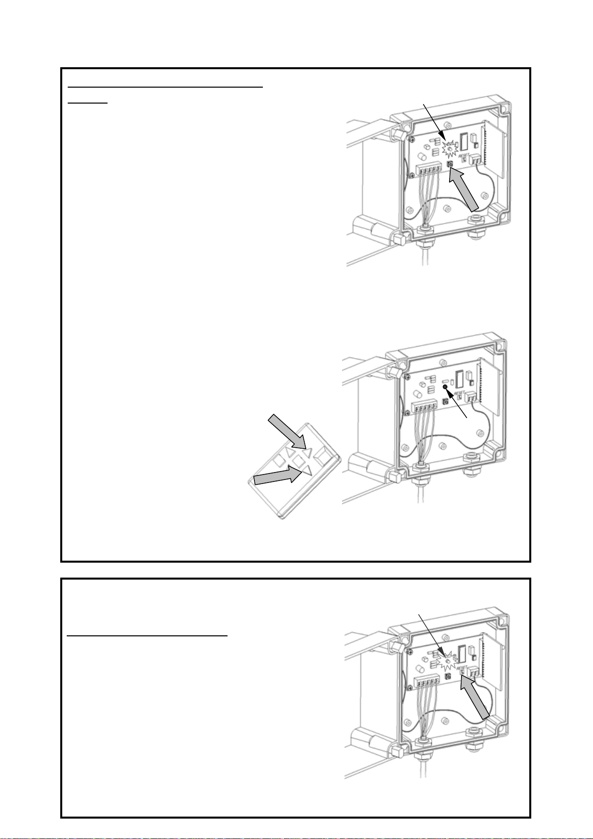
Each output can be independently configured in 3 operating modes:
- Pulse command mode : The output relay is activated when you press the transmitter command
key and is deactivated as soon as you release the key. This mode is particularly suitable for
automatic gate devices, garage door devices, etc.
- Timing mode : This mode can start the operation of a device for a programmed time period (7,5
minute max), at the end of the time period the device will automatically stop operating. This mod
e
is use ful for turning on outdoor lighting for a short time period.
- Bistable mode : The transmitter sends a command to activate a device. A second order is
necessary to stop the device. This mode is ideal for indoor or outdoor lighting.
The universal receiver comes in a waterproof cabinet (IP55) with an internal transformer.
A 99 channel transmitter can update several universal receivers.
However, several 99 channel transmitters can also be used to operate the same output of a
universal receiver.
A channel number on the 99 channel transmitter is assigned to the universal receiver output
during the configuration phase. The operating mode is also selected during this phase.
It is possible to assign the 3 operating modes to the same output by storing a specific channel
number for each operating mode during the configuration phase.
Example: Channel 18 can operate output 1 on the receiver in the pulse command mode, channel 25
can operate the same output 1 of the same universal receiver in the timing mode, and channel 37
can operate output 1 of the same receiver in the bistable mode.
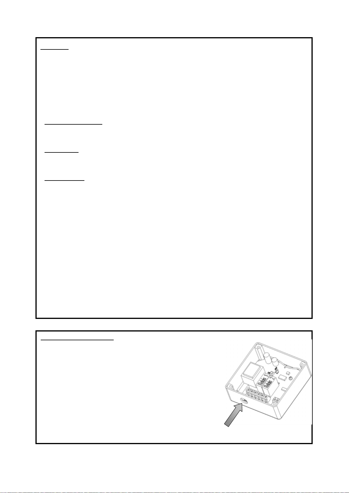
230v power supply wiring:
- Carrefully pierce the cabinet under the terminals numbered 1 and
2.
- We recommend using a cable gland (not included) to make sure
that the cabinet remains waterproof.
- Insert the 230V wire into the cable gland.
- Screw the wires to terminal 1 and 2 (230VAC and L N).
- Tighten the cable gland.
9

Tips on wiring the universal receiver relay outputs:
* Used for an automatic gate or garage door (diagram A): Connect the universal receiver relay
output to the push-button terminal on the device's electronic control panel. If the terminal is
already used for a push-button, wire the relay outlets in parallel to the push-button. Important:
configure the output in the pulse command mode.
* Used for lighting operated by a switch (diagram B) : Connect the relay output in parallel to the
switch. Make sure that the power consumed by the lighting is lower than the maximum relay
capacity (2000W). Configure the output in the bistable or timing mode.
* Used for lighting operated by a latching switch (diagram C) : Connect the relay output on the
universal receiver in parallel to a push-button or directly to the push-button terminal on the
latching switch. Configure the output in the pulse command mode.
A
B
C
Automatic gate
electronic panel
External push-button terminal
Before
Before
After
After
After
Existing
switch
Existing
Push-
btt
10

PULSE COMMAND MODE
Single pulse configuration of the first output and channel
assignment:
1- Select the channel on the 99 channel transmitter.
2- Press the SW1 push-button on the receiver one time.
3- The L1 LED turns on for 5 seconds.
4- During the 5 seconds, press the top arrow key on the
transmitter to send a command to the receiver.
5- The selected channel is now stored and will activate the first
output on the universal receiver.
Test operation in the single pulse mode: Display the previously
stored channel on the transmitter. Press the top arrow key, relay
#1 (terminals 3-4) and the L1 LED will remain activated as a long
as you hold down the key. As soon as you release the arrow key,
the relay is deactivated and the L1 LED turns off.
1
2
3
4
1
2
3
4
Single pulse configuration of the second output and channel
assignment:
1- Select the channel on the 99 channel transmitter.
2- Press the SW1 push-button on the receiver two times.
3- The L2 LED turns on for 5 seconds.
4- During the 5 seconds, press the top arrow key on the
transmitter to send a command to the receiver.
5- The selected channel is now stored and will activate the
second output on the universal receiver.
Test operation in the single pulse mode: Display the previously
stored channel on the transmitter. Press the top arrow key,
relay #2 (terminals 5-6) and the L2 LED will remain activated as
a long as you hold down the key. As soon as you release the
arrow key, the relay is deactivated and the L2 LED turns off.
11

Number of Duration Number of Duration
Flashes Flashes
1 1s 16 30s
2 2s 17 1min
3 3s 18 1,5min
4 4s 19 2min
5 5s 20 2,5min
6 6s 21 3min
7 7s 22 3,5min
8 8s 23 4min
9 9s 24 4,5min
10 10s 25 5min
11 11s 26 5,5min
12 12s 27 6min
13 13s 28 6,5min
14 14s 29 7min
15 15s 30 7,5min
31 Bistable
TIMING MODE
1
2; 4; 6 3; 5; 7; 8
8
Timing mode configuration of the first output and channel
assignment:
1- Display your desired channel on your transmitter.
2- Press and hold down the SW1 push-button on the receiver.
3- The L1 LED turns on for several seconds and then turns off.
4- Release the SW1 push-button.
5- The L1 LED begins to flash. Each flash corresponds to a
duration indicated in the above chart.
6- Count the number of flashes. Press the SW1 push-button again
when the number of flashes corresponds to your desired duration.
7- The L1 LED will remain on for 5 seconds.
8- During this time, press the top arrow key on the transmitter
and hold it down until the L1 LED goes out.
Test operation in the timing mode: Display the previously stored
channel on the transmitter. Press the top arrow key. Relay #1
(terminals 3-4) and the L1 LED will remain activated for the
programmed duration.
The chart below is important. It is used to set the timing mode duration during programming.
12

1
2; 4; 6; 8 3
10
Timing mode configuration of the second output and channel
assignment:
1- Display your desired channel on your transmitter.
2- Press and then release the SW1 push-button on the receiver.
3- The L1 LED turns on for several seconds.
4- Hold down the SW1 push-button.
5-The L2 LED turns on and then goes off.
6- Release the SW1 push-button.
7- The L2 LED begins to flash. Each flash corresponds to a
duration indicated in the above chart.
8- Count the number of flashes. Press the SW1 push-button again
when the number of flashes corresponds to your desired
duration.
9- The L2 LED will remain on for 5 seconds.
10- During this time, press the top arrow key on the transmitter
and hold it down until the L2 LED goes out.
Test operation in the timing mode: Display the previously stored
channel on the transmitter. Press the top arrow key. Relay #2
(terminals 5-6) and the L2 LED will remain activated for the
programmed duration.
5; 7; 9
13

BISTABLE MODE
1
2; 4 3; 5; 6; 7; 8
8
Bistable mode configuration of the first output and channel
assignment:
1- Select your desired channel on the transmitter.
2- Hold down the SW1 push-button on the receiver.
3- The L1 LED turns on for several seconds and then goes off.
4- Release the SW1 push-button.
5- The L1 LED begins to flash.
6- Wait for the final flash (31.st flash).
7-The L1 LED will remain on for 5 seconds.
8- During this time, press and hold down the top arrow key on the
transmitter until the L1 LED turns off.
Test operation in the bistable mode: Display the previously stored
channel on the transmitter. Press the top arrow key, relay #1
(terminals 3-4) and the L1 LED become and remain activated. To
deactivate them, press the top arrow key again.
1
2; 4; 6; 8 3
10
Bistable mode configuration of the second output and channel
assignment:
1- Select your desired channel on the transmitter.
2- Press and release the SW1 push-button on the receiver.
3- The L1 LED turns on for several seconds.
4- Hold down the SW1 push-button.
5- The L2 LED turns on and then turns off.
6- Release the SW1 push-button.
7- The L2 LED begins to flash.
8- Wait for the last flash (31 st flash) in the series.
9- The L2 LED turns on for 5 seconds.
10- During this time, press and hold down the top arrow key until
the L2 LED goes out.
Test operation in the bistable mode: Display the previously stored
mode on the transmitter screen. Press the top arrow key. The #2
relay (terminals 5-6) and the L2 LED become and remain activated.
To deactivate them, press the top arrow key a second time.
5; 7; 8; 9
14

COMPLETELY ERASE ALL STORED CHANNELS
1- Disconnect the 230V power supply from the universal receiver.
2- Press and hold down the SW1 push-button.
3- Simultaneously re-connect the 230V power supply.
4- The leds on the receiver begin flashing.
5- The receiver memory is erased. The stored channels are erased.
15
Table of contents